KLX 135A
KLX 135A
KLX 135A
- No tags were found...

You also want an ePaper? Increase the reach of your titles
YUMPU automatically turns print PDFs into web optimized ePapers that Google loves.
D To go Direct To a waypoint:1. Press the D button. The Direct To (DIR) page will be displayed with a waypointfield.2. Enter desired waypoint using right concentric knobs.3. Press F to view waypoint information. Press F again to confirm. This initiatesthe Direct To—your D-bar will be centered, and you’re on your way!4. Alternatively, display desired waypoint on APT, VOR, NDB or SUP page, or movethe cursor over desired waypoint in the active flight plan, then press D, thenpress F to confirm.To create a Flight Plan:1. Select the active Flight Plan (FPL 0) or one of the stored Flight Plans (FPL 1through FPL 9) on the screen.2. Delete existing waypoints from the Flight Plan as necessary by placing the cursor(B) over the identifier, pressing E, and then pressing F.3. If you wish to insert a waypoint identifier between two other waypoints, place thecursor (B) over the waypoint you wish for the new waypoint to precede.4. With the cursor on, enter the desired waypoint identifier and press F.5. The waypoint page for the selected identifier will be displayed. If this is the waypointyou intended to enter, press F again.6. Repeat the waypoint entry process as needed for your Flight Plan.To calculate the winds aloft:1. Use the CAL 3 page to calculate the present pressure altitude.2. Use the CAL 5 page to calculate the present true airspeed (TAS).3. Turn to the CAL 6 page and enter the present aircraft heading. The headwind ortailwind component of the wind, and the wind vector (direction and speed) will bedisplayed on the last two lines of the CAL 6 page.-2-
NAV 5 (Moving Map) Page TipsTo change the map scale factor:1. Press the B button. The cursor comes up over the map scale in thelower left corner of the map display.2. Use the right inner knob to change between scale factors.3. For terminal area operations select AUTO scale factor.To change what information is displayed on the map:1. Press the B button, select Menu? and press the F button to bringup a pop-up menu.(Figure 3)118.00136.97{>Leg17.6nmSUA:offOMNVOR:off% % %GJORLKORLAPT:off%112°KJAX ">117ktAPT VOR NDB SUP ACT NAV FPL CAL SET OTHFigure 3• Line 1: Display 5 nearest special use airspaces (SUAs), on or off• Line 2: Display 9 nearest VORs; on or off• Line 3: Display 9 nearest airports; on or off• Line 4: Map orientation; N↑=North up, DTK↑=Desired track up, TK↑ =Actual track up (when groundspeed > 2 kts)2. Use the right outer knob to select the desired item, and the right innerknob to change the setting.To change the navigation info displayed in the lower right corner:1. Press the B button.2. Use the right outer knob to move the cursor to the cyclic field in the lowerright corner.3. Press E to change between the choices, which are:• Groundspeed,• Estimated Time En route (ETE) to the active waypoint (figure 6),• Crosstrack correction, or• Magnetic Desired Track (DTK).-3-
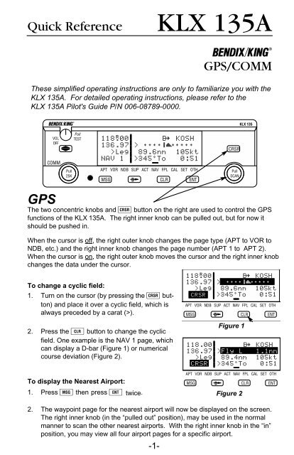
COMMThe two concentric knobs and A (transfer)button on the left are used to control the COMMfunctions of the <strong>KLX</strong> <strong>135A</strong>.A small “R” appears over the decimal point of theactive frequency when the squelch is broken andthe radio is receiving (Figure4). When the transmitteris keyed a small “T” appears in this same spot.To tune a COMM frequency:Figure 41. Use the left outer knob to select the desired number of megahertzbetween 118 and 136.2. Make sure the left inner knob is pushed in, and use it to complete thedesired frequency. In this case, the left inner knob changes the frequencyin increments of 0.05 MHz (50 kHz).To tune a 25 kHz frequency:1. Pull the left inner knob out.2. Use the left knobs to tune the frequency. Notice that the <strong>KLX</strong> <strong>135A</strong> onlydisplays two digits after the decimal point, so the last digit is implied. Forexample, if the frequency is 123.125 MHz, the <strong>KLX</strong> <strong>135A</strong> displays 123.12.3. When you’re ready to go back to 50 kHz tuning, push the left inner knobback in. This will allow you to select frequencies with fewer turns of theknob.To use the standby frequency entry (flip-flop) mode:Note: This is the default frequency entry mode.B1. Use the left knobs to tune the standby COMM frequency.2. To exchange (flip-flop) the active and standby frequencies,press the A button.VOLOFFCOMMPull25KPullTEST118®40123.12>LegNAV 1APT VOR NDBMSGDTo use the active frequency entry mode:1. Press and hold the A button for approximately2 seconds. The standby frequencywill disappear and the active frequency willbe the same as before you pressed the Abutton (Figure 5).2. You can now use the left knobs to tune theactive COMM frequency.BVOLOFFCOMMPull25KPullTEST118.40>LegNAV 1APT VOR NDB SMSGFigure 5D3. To change back to standby frequency entry mode, press the A buttonmomentarily.-4-
How to QuickTune a COMM frequency from the data base:1. Locate the page for the facility you desire to communicate with (APT,FSS or CTR). The APT 4 page displays the frequency type (TWR =Tower Freq, GRND = Ground Control, etc.) and frequency (Figure 6).B<strong>KLX</strong> 135VOLOFFCOMMPull25KPullTEST136.97 KDAL118.00 ATIS 120.15>Leg CLR 127.90APT+4 GRND 121.75APT VOR NDB SUP ACT NAV FPL CAL SET OTHMSGDCLRENTCRSRGPSPullSCANFigure 62. Press the B button to turn the cursor on and use the right outer knobto scan through all the airport’s frequencies (Figure 7). There may bemore frequencies than can be displayed at one time.B<strong>KLX</strong> 135VOLOFFCOMMPull25KPullTEST136.97 KDAL118.00 ATIS 120.15ÉÑ>Leg CLR 127.90APT+4 GRND 121.75APT VOR NDB SUP ACT NAV FPL CAL SET OTHMSGDCLRENTCRSRGPSPullSCANFigure 73. When you have the cursor over the desired frequency, press Fand that frequency will become the standby frequency in the COMMtransceiver (Figure 8).B<strong>KLX</strong> 135VOLOFFCOMMPull25KPullTEST136.97 KDAL120.15 ATIS 120.15>Leg CLR 127.90APT+4 GRND 121.75APT VOR NDB SUP ACT NAV FPL CAL SET OTHMSGDCLRENTCRSRPullSCANGPSFigure 8To adjust the volume by overriding the automatic squelch:1. Pull out on the small knob in the upper left cornerof the <strong>KLX</strong> <strong>135A</strong> (Figure 9). This will eitherallow you to receive a distant, weak signal orVOLgive you a noise reference by which to adjustOFFthe volume.B2. Push the volume knob back in for normal squelch operation.PullTESTFigure 9-5-
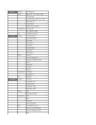
Finding your way around:There are ten types of pages that may be displayed on the right side of the screen.Each has multiple page numbers:Airport (APT) Pages1 Airport identifier, elevation, name, city,state/province/country, use type (ifmilitary or private-use)2 Latitude/longitude, bearing/radial anddistance relative to present position3 Runway numbers, length, surface, lighting4 Airport communication frequencies5 Airport remarksVOR Pages1 VOR identifier, frequency, name,latitude/longitude2 Magnetic station declination, bearing/radial, distance relative to present positionNDB Pages1 NDB identifier, frequency, name,latitude/longitude2 Bearing/radial and distance relative to presentpositionSupplemental (SUP) Pages0 Used to choose method of user-definedwaypoint creation1 Latitude/Longitude, bearing/radial anddistance relative to present position2 Reference waypoint (default is nearbyVOR), radial and distance from reference3 User-defined waypoint remarksActive Waypoint (ACT) PagesWaypoint pages for the active waypointand the waypoints in FPL 0Navigation (NAV) Pages1 Active waypoint/leg, CDI/crosstrackdistance, ground speed,bearing, time to active waypoint2 Present position (latitude/longitude or radial/distance)3 Present time, departure time, ETA atdestination, elapsed flight time4 Desired track, actual track, bearing toactive waypoint5 Moving mapFlight Plan (FPL) Pages0 Active flight plan1-9 Stored (numbered) flight plansCalculator (CAL) Pages1 Trip calculations for distance, bearing, andETE2 Trip calculations for fuel requirements3 Pressure altitude4 Density altitude5 True airspeed (TAS)6 Winds aloftSetup (SET) Pages1 Position initialization for GPS receiver2 Date, time, and time zone initialization3 Data base update4 Turn anticipation enable/disable5 Default first waypoint character6 Nearest airport criteria7 SUA alert enable/disable8 Baro set, indicated altitude, baro set unitsOther (OTH) Pages1 GPS receiver state, estimated positionerror2 GPS satellite signal status3 List of user-defined waypoints4 List of airports and user-definedwaypoints with stored remarks5 Software versionsAlliedSignal Inc.Electronic & Avionics SystemsOne Technology Center23500 West 105th StreetOlathe, KS 66061Telephone (913) 782-0400©1995, 1996 AlliedSignal Inc.A7/96 006-08790-0000 Printed in USA