G1000 Trainer Bezel Overview - Sporty's
G1000 Trainer Bezel Overview - Sporty's
G1000 Trainer Bezel Overview - Sporty's

You also want an ePaper? Increase the reach of your titles
YUMPU automatically turns print PDFs into web optimized ePapers that Google loves.
Interface <strong>Overview</strong><br />
The <strong>G1000</strong> <strong>Trainer</strong> interface is composed of a menu bar, the <strong>G1000</strong> Control Display Unit<br />
(CDU) bezel and the <strong>G1000</strong> Control Display.
Menu Bar<br />
The menu bar is located across the top of the <strong>G1000</strong> <strong>Trainer</strong> interface window and<br />
consists of the following menus (corresponding menu options are listed in<br />
parentheses):<br />
File (Power-up; Exit)<br />
Options (Screen Capture; Reversionary Mode; PFD Mode; MFD Mode;<br />
Simulate Failures, Pause, Joystick Axis Configuration, WFDE Prediction<br />
Program, Enable Sound)<br />
The ‘Screen Capture’ menu option allows the user to capture screenshots<br />
of the <strong>G1000</strong> <strong>Trainer</strong> interface. These screenshots are generated in<br />
bitmap format (".bmp" file extension) and are automatically saved in the<br />
same file folder as the one in which the <strong>G1000</strong> <strong>Trainer</strong> software<br />
application was installed.<br />
Airframe (displays a list of selectable airframes)<br />
Help (<strong>G1000</strong> <strong>Trainer</strong> Help; About)
<strong>G1000</strong> <strong>Trainer</strong> <strong>Bezel</strong><br />
The <strong>G1000</strong> <strong>Trainer</strong> bezel surrounds the control display and consists of the same knobs, keys<br />
and softkeys as those found on the <strong>G1000</strong> system.
<strong>G1000</strong> Control Display<br />
The <strong>G1000</strong> control display is surrounded by the control bezel and can be configured as either a Primary Flight<br />
Display (PFD) or as a Multi Function Display (MFD).<br />
The <strong>G1000</strong> trainer also supports a dual screen mode, allowing the PFD and MFD to be used simultaneously.
Opening and Powering Up the <strong>G1000</strong> <strong>Trainer</strong><br />
To open the <strong>G1000</strong> <strong>Trainer</strong>:<br />
1a. Double-click the <strong>G1000</strong> <strong>Trainer</strong> shortcut located on the PC desktop (the<br />
‘Shortcut on Desktop’ option is selected by default at installation).<br />
or<br />
1b. Click the <strong>G1000</strong> <strong>Trainer</strong> shortcut located in the PC Start menu under ‘Programs’<br />
(the ‘Shortcut in Start Menu’ option is selected by default at installation).<br />
To power up the <strong>G1000</strong> <strong>Trainer</strong>:<br />
1a. Click the power button located at the top left corner of the <strong>G1000</strong> <strong>Trainer</strong> bezel.<br />
or<br />
1b. Click the ‘File’ menu and select ‘Power-up’.<br />
Upon power-up, the system typically takes several seconds to initialize.<br />
Only when the <strong>G1000</strong> system is powered up in MFD mode is the Power-up<br />
Page displayed. The Power-up Page provides checklist information as<br />
well as land, terrain and aviation database information.
To exit the Power-up Page and display the MAP Page, press the ENT key<br />
or press the first softkey from the right (or press ‘F12’).
Starting the <strong>G1000</strong> <strong>Trainer</strong> in Dual Screen Mode<br />
To display the <strong>G1000</strong> <strong>Trainer</strong> in Dual Screen mode:<br />
1. On the Start Menu, select ‘Programs’, ‘<strong>G1000</strong> <strong>Trainer</strong>’, and then ‘Start Dual<br />
Screen <strong>Trainer</strong>’. Both the <strong>G1000</strong> <strong>Trainer</strong> PFD and the <strong>G1000</strong> <strong>Trainer</strong> MFD<br />
display.<br />
2. On the Start Menu, select ‘Programs’, ‘<strong>G1000</strong> <strong>Trainer</strong>’, and then ‘Start<br />
Remotes’. This launches the remotes for the PFD and the MFD.<br />
3. Click the power buttons located at the top left corners of the <strong>G1000</strong> <strong>Trainer</strong><br />
bezels.<br />
The AFCS Controls work with the PFD. The Garmin Control Unit works<br />
with the MFD.
Pausing the <strong>G1000</strong> <strong>Trainer</strong><br />
Pausing the <strong>Trainer</strong> causes the airspeed, altitude, vertical speed and position of the<br />
aircraft to be paused.<br />
To pause the <strong>G1000</strong> <strong>Trainer</strong>:<br />
Click the ‘Options’ menu and select ‘Pause’.<br />
or<br />
Right-click anywhere on the control display and select ‘Pause’.<br />
To resume the <strong>Trainer</strong> session, deselect the ‘Pause’ option either in the<br />
‘Options’ pull-down menu or in the right-click menu.
Stopping and Closing the <strong>G1000</strong> <strong>Trainer</strong><br />
To stop the <strong>G1000</strong> <strong>Trainer</strong>:<br />
Click the power button.<br />
To stop and close the <strong>G1000</strong> <strong>Trainer</strong>:<br />
Click the ‘File’ menu and select the ‘Exit’ menu option.<br />
or<br />
Click the ‘x’ icon located at the top right corner of the <strong>G1000</strong> <strong>Trainer</strong> window.
<strong>G1000</strong> <strong>Trainer</strong> Control <strong>Overview</strong><br />
The <strong>G1000</strong> <strong>Trainer</strong> is operated via the following external controls:<br />
External joystick, as indicated by the minimum system requirements<br />
PC mouse<br />
Keyboard
External Joystick<br />
The external joystick is used to emulate pilot control inputs during flight.<br />
A four-axis joystick with throttle/power and rudder control is<br />
recommended for the <strong>G1000</strong> <strong>Trainer</strong>.
PC Mouse<br />
The PC mouse is used to control the <strong>G1000</strong> <strong>Trainer</strong> knobs, keys and softkeys.
Keyboard Shortcuts<br />
A number of <strong>G1000</strong> controls can be activated on the <strong>G1000</strong> <strong>Trainer</strong>, using keyboard shortcuts. The<br />
following shortcuts are available:<br />
‘W’ activates the power button.<br />
‘F1’ to ’F12’ respectively activate softkeys 1 through 12 (where softkey numbers are defined by the<br />
position of the softkey from left to right on the display).<br />
‘D’ activates the Direct-to key.<br />
‘M’ activates the MENU key.<br />
‘F’ activates the FPL key.<br />
‘P’ activates the PROC key.<br />
‘ESC’ activates the CLR key.<br />
‘Enter’ (carriage return) activates the ENT key.<br />
The space bar presses the FMS knob.<br />
The arrow keys rotate the FMS knob as follows:<br />
- Down arrow turns the large FMS knob clockwise (upper right arrow on the display).<br />
- Up arrow turns the large FMS knob counterclockwise (upper left arrow on the display).<br />
- Right arrow turns the small FMS knob clockwise (lower right arrow on the display).<br />
- Left arrow turns the small FMS knob counterclockwise (lower left arrow on the display).<br />
The number keys on the number keypad activate the bezel joystick used to pan the map.<br />
The number keypad shortcuts are not available on laptop computers.<br />
‘Alt’ + ‘F’ pulls down the ‘File’ menu<br />
‘Alt’ + ‘O’ pulls down the ‘Options’ menu<br />
‘Alt’ + ‘A’ pulls down the ‘Airframe’ menu<br />
‘Alt’ + ‘H’ pulls down the ‘Help’ menu<br />
‘N’ = ‘F11’ displays and hides the NRST window PFD only<br />
‘Y’ = ‘F12’ displays and hides the ALERTS window PFD only
Configuring the External Joystick<br />
If the external joystick is not already configured adequately to simulate pilot control<br />
inputs on the <strong>G1000</strong> <strong>Trainer</strong>, it can be configured by the user before system<br />
power-up.<br />
Joystick axis configuration can only be performed before the <strong>G1000</strong><br />
system is powered up. If the joystick settings are changed while the<br />
<strong>G1000</strong> system is powered up, the <strong>Trainer</strong> has to be restarted for the<br />
changes to take effect.<br />
To configure the joystick axes on the <strong>G1000</strong> <strong>Trainer</strong>:<br />
1. Click the ‘Options’ menu and select ‘Joystick Axis Configuration’.<br />
2. Configure the external joystick axes as appropriate.<br />
The external joystick axes should be configured according to the<br />
standard pilot control inputs.
3. Click the ‘OK’ button.<br />
The original external joystick axis configuration settings can be restored<br />
by clicking the ‘Default Config’ button, then by clicking the ‘OK’ button on<br />
the Joystick Axis Configuration window.
<strong>G1000</strong> <strong>Trainer</strong> <strong>Bezel</strong> <strong>Overview</strong><br />
With the exception of the power button (button which is not present on the <strong>G1000</strong><br />
Control Display Unit), the <strong>G1000</strong> <strong>Trainer</strong> bezel knobs, keys and softkeys are similar<br />
to and work in the same manner as those found on the <strong>G1000</strong> system.<br />
The <strong>G1000</strong> <strong>Trainer</strong> bezel includes the following controls:<br />
Power button<br />
NAV VOL/ID knob<br />
NAV Frequency Toggle key<br />
NAV knob<br />
HDG knob<br />
ALT knob<br />
COM knob<br />
COM Frequency Toggle key<br />
COM VOL/SQ knob<br />
CRS/BARO knob<br />
RANGE joystick<br />
Direct-to key<br />
MENU key<br />
FPL key<br />
PROC key<br />
CLR key<br />
ENT key<br />
Dual FMS knob<br />
12 softkeys
Knobs, Keys and Softkeys<br />
The <strong>G1000</strong> <strong>Trainer</strong> bezel knobs, keys and softkeys are similar to and work in the same manner as<br />
those found on the <strong>G1000</strong> system.<br />
The softkeys are located across the bottom of the display and are designed to perform various<br />
functions depending upon the control display mode and the specific page being displayed.<br />
Placing the mouse pointer over a key/softkey/knob and clicking it with the left mouse button is equivalent<br />
to pressing the key/softkey/knob of interest.<br />
In addition, arrows are displayed around the knobs of the <strong>G1000</strong> <strong>Trainer</strong> bezel in order to enable<br />
simulation of knob rotation.
Power Button<br />
Although the <strong>G1000</strong> System does not feature a power button, such a button has been added to<br />
the top left corner of the <strong>G1000</strong> <strong>Trainer</strong> bezel for practical purposes.<br />
Pressing the power button when the <strong>G1000</strong> system is not running starts the system.<br />
Conversely, pressing the power button while the <strong>G1000</strong> system is running stops the<br />
system.
AFCS Controls<br />
The AFCS Controls work with the PFD. Click the buttons to simulate selecting the controls on the<br />
<strong>G1000</strong> <strong>Trainer</strong>.<br />
The controls for your trainer may differ slightly. In addition, not all aircraft are equipped<br />
with AFCS controls .<br />
The AFCS Controls consist of the following:<br />
1. HDG Key – Selects/deselects Heading Select Mode.<br />
2. APR Key – Selects/deselects Approach Mode.<br />
3. NAV Key – Selects/deselects Navigation Mode.<br />
4. FD Key – Activates/deactivates the flight director in the default pitch and roll modes. If the<br />
autopilot is engaged, the FD Key is disabled.<br />
5. XFR Key – Switches the autopilot between the pilot-side and the copilot-side flight directors.<br />
This selection also selects which air data computer is communicating with the active<br />
transponder and which PFD triggers the altitude alert. Upon power-up, the pilot-side FD is<br />
selected.<br />
6. ALT Key – Selects/deselects Altitude Hold Mode.<br />
7. VS Key – Selects/deselects Vertical Speed Mode.<br />
8. FLC Key – Selects/deselects Flight Level Change Mode.<br />
9. CRS2 Knob – Sets the copilot-selected course on the HSI of PFD2 when the VOR1, VOR2, or<br />
OBS/SUSP mode is selected. Pressing this knob centers the CDI on the currently selected<br />
VOR. The copilot-selected course provides course reference to the copilot-side flight director<br />
when operating in Navigation and Approach Modes.<br />
10. SPD Key – Switches the Flight Level Change Mode reference speed between IAS and MACH<br />
number.<br />
11. NOSE UP/DN Wheel – Controls the active mode reference for the Pitch, Vertical Speed, and<br />
Flight Level Change Modes.<br />
12. VNV Key – Selects/deselects Vertical Navigation Mode.<br />
13. ALT SEL Knob – Sets the selected altitude in the Selected Altitude Box. In addition to<br />
providing the standard <strong>G1000</strong> altitude alerter function, selected altitude provides an altitude<br />
setting for the Altitude Capture/Hold mode of the AFCS.
14. YD Key – Engages/disengages the yaw damper.<br />
15. AP Key – Engages/disengages the autopilot.<br />
16. BANK Key – Selects/deselects Low Bank Mode.<br />
17. CRS1 Knob – Sets the pilot-selected course on the HSI of PFD1 when the VOR1, VOR2, or<br />
OBS/SUSP mode is selected. Pressing this knob centers the CDI on the currently selected<br />
VOR. The pilot-selected course provides course reference to the pilot-side flight director when<br />
operating in Navigation and Approach Modes.<br />
18. BC Key – Selects/deselects Back Course Mode.<br />
19. HDG Knob – Sets the selected heading on the HSI. When operating in Heading Select mode,<br />
this knob provides the heading reference to the flight director.<br />
The AFCS Controls work with the PFD. The Garmin Control Unit works with the MFD.
Garmin Control Unit<br />
The controls for the MFD are located on both the MFD bezel and the Garmin Control Unit.<br />
The controls for your trainer may differ slightly. In addition, not all aircraft are<br />
equipped with a Garmin Control Unit.<br />
The controls for the Garmin Control Unit consist of the following:<br />
1. Dual FMS Knob – Flight Management System Knob. This knob selects the MFD page to<br />
be viewed; the large knob selects a page group (MAP, WPT, AUX, NRST), while the<br />
small knob selects a specific page within the page group. Pressing the FMS Knob turns<br />
the selection cursor ON and OFF. When the cursor is ON, data may be entered in the<br />
applicable window by turning the small and large knobs. In this case, the large knob<br />
moves the cursor on the page, while the small knob selects individual characters for the<br />
highlighted cursor location.<br />
2. Direct-to Key – Allows the user to enter a destination waypoint and establish a direct<br />
course to the selected destination. (The destination is specified by the identifier, chosen<br />
from the active route, or taken from the map pointer position.)
3. FPL Key – Displays the active Flight Plan Page for creating and editing the active flight<br />
plan, or for accessing stored flight plans.<br />
4. MENU Key – Displays a context-sensitive list of options. This list allows the user to<br />
access additional features or make setting changes that relate to particular pages.<br />
5. PROC Key – Gives access to IFR departure procedures (DPs), arrival procedures<br />
(STARs) and approach procedures (IAPs) for a flight plan. If a flight plan is used,<br />
available procedures for the departure and/or arrival airport are automatically suggested.<br />
Theses procedures can then be loaded into the active flight plan. If a flight plan is not<br />
used, both the desired airport and the desired procedure may be selected.<br />
6. Joystick – Changes the map range when rotated. Activates the map pointer when<br />
pressed.<br />
7. Alphanumeric Keys – Allow the user to enter data quickly, without having to select<br />
individual characters with the FMS Knob.<br />
8. Plus (+) Minus (-) Key – Toggles a (+) or (-) character.<br />
9. Decimal Key – Enters a decimal point.<br />
10. SEL Key – The center of this key activates the selected softkey, while the right and left<br />
arrows move the softkey selection box to the right and left, respectively.<br />
40. ENT Key – Validates or confirms a menu selection or data entry.<br />
41. CLR Key – Erases information, cancels entries, or removes page menus. Pressing and<br />
holding this key displays the Navigation Map Page automatically.<br />
42. SPC Key – Adds a space character.<br />
43. BKSP Key – Moves the cursor back one character space.<br />
The AFCS Controls work with the PFD. The Garmin Control Unit works with the<br />
MFD.
<strong>G1000</strong> System Control <strong>Overview</strong><br />
The <strong>G1000</strong> system bezel features the following controls:<br />
NAV VOL/ID knob<br />
NAV Frequency Toggle key<br />
NAV knob<br />
HDG knob<br />
ALT knob<br />
COM knob<br />
COM Frequency Toggle key<br />
COM VOL/SQ knob<br />
CRS/BARO knob<br />
RANGE joystick<br />
Direct-to key<br />
MENU key<br />
FPL key<br />
PROC key<br />
CLR key<br />
ENT key<br />
Dual FMS knob
NAV Knob<br />
The dual NAV knob tunes NAV frequencies in the tuning box.<br />
Turning the large NAV knob tunes the MHz portion the frequency.<br />
Turning the small knob tunes the kHz portion of the frequency.<br />
Pressing the NAV knob toggles the tuning box between the NAV radios.
NAV Frequency Toggle Key<br />
The NAV Frequency Toggle key toggles the NAV frequencies between the active and standby<br />
fields.
NAV VOL/ID Knob<br />
The NAV VOL/PUSH ID knob adjusts NAV radio volume level (turn) and turns the Morse code<br />
identifier ON and OFF (press).
HDG Knob<br />
The HDG knob selects heading. When this knob is pressed, a window displaying digital heading<br />
appears momentarily to the left of the Heading indicator and the Heading bug is synchronized<br />
with the compass lubber line.
ALT Knob<br />
The dual ALT knob is composed of both a large knob and a small knob and sets the reference<br />
altitude.<br />
The large knob sets the thousands of feet or meters.<br />
The small knob selects the hundreds of feet or meters.
COM Knob<br />
The dual COM knob tunes COM frequencies in the tuning box.<br />
Turning the large COM knob tunes the MHz portion the frequency.<br />
Turning the small knob tunes the kHz portion of the frequency.<br />
Pressing the COM knob toggles the tuning box between the COM radios.
COM Frequency Toggle Key<br />
The COM Frequency Toggle key toggles the COM frequencies between the active and standby<br />
fields.<br />
Pressing and holding the COM Frequency Toggle key for approximately two seconds<br />
tunes the emergency frequency (121.500) in the active COM field.
COM VOL/SQ Knob<br />
The COM VOL/PUSH SQ knob adjusts COM radio volume level (turn) and turns automatic<br />
squelch ON and OFF (press).
CRS/BARO Knob<br />
The CRS/BARO knob is composed of both a large knob and a small knob.<br />
The large knob (BARO knob) sets the altimeter.<br />
The small knob (CRS knob) adjusts course.
RANGE Joystick<br />
The RANGE joystick changes the map scale when rotated and activates the map pointer when<br />
pressed.
Direct-to Key<br />
The Direct-to key enters a destination waypoint and establishes a direct course to this waypoint<br />
(the direct-to waypoint can be selected by its name identifier, from the active route, or from the<br />
map cursor position).
MENU Key<br />
The MENU key displays a context-sensitive list of options which allows the user to access<br />
additional features or make setting changes that relate to certain pages.
FPL Key<br />
The FPL key accesses the active Flight Plan Page; this page is used to create flight plans, edit<br />
active flight plans, or access stored flight plans.
PROC Key<br />
The PROC key selects departure, approach and arrival procedures from the database to add to<br />
a flight plan.
CLR Key<br />
The CLR key erases information or cancels data entry. When pressed and held, this key also<br />
displays the Navigation Map Page (MFD only).
ENT Key<br />
The ENT key confirms selections and operations, and completes and approves data entry.
Dual FMS Knob<br />
The dual FMS knob is used on the MFD and is composed of both a large knob and a small<br />
knob.<br />
The large knob selects a page group (MAP, WPT, AUX, NRST).<br />
The small knob selects a specific page within the selected page group.<br />
Pressing the FMS knob activates and deactivates the selection cursor on the selected page.<br />
When the selection cursor is activated, data may be entered using both the small knob and the<br />
large knob. In this case, the large knob moves the selection cursor on the page, while the small<br />
knob selects individual characters for data entry.
Control Display Modes<br />
The <strong>G1000</strong> control display can be configured at any time—that is, whether the system is running or not—as<br />
either a Primary Flight Display (PFD) or a Multi Function Display (MFD).<br />
The <strong>G1000</strong> control display can also be set at any time to reversionary mode, or backup mode, a mode in which all<br />
important flight information from both the PFD and the MFD is presented.
PFD Mode<br />
In PFD mode, the control display presents information included in the six-pack<br />
instruments (that is, attitude, airspeed, altitude, vertical speed, heading, slip/skid<br />
and turn rate).<br />
To configure the <strong>G1000</strong> <strong>Trainer</strong> as a PFD:<br />
Click the ‘Options’ menu and select the ‘PFD Mode’ menu option.<br />
or<br />
Right-click anywhere on the control display and select ‘PFD Mode’.
MFD Mode<br />
In MFD mode, the control display presents information associated both with<br />
navigation and with the Engine Indication System (EIS).<br />
To configure the <strong>G1000</strong> <strong>Trainer</strong> as an MFD:<br />
1a. Click the ‘Options’ menu and select the ‘MFD Mode’ menu option.<br />
or<br />
1b. Right-click anywhere on the control display and select ‘MFD Mode’.
Reversionary Mode<br />
Reversionary (or backup) mode is a mode of operation in which both the PFD and<br />
MFD are identically configured to display all of the important flight parameters in<br />
the event of display failure.<br />
To set the <strong>G1000</strong> <strong>Trainer</strong> to Reversionary mode:<br />
Click the ‘Options’ menu and select ‘Reversionary Mode’.<br />
or<br />
Right-click anywhere on the control display and select ‘Reversionary Mode’.<br />
Deselecting ‘Reversionary Mode’ returns the display to the normal display<br />
mode that was selected before reversionary mode was activated (i.e.,<br />
either PFD or MFD).
Demo Mode<br />
When no external joystick is connected to the PC, the <strong>G1000</strong> <strong>Trainer</strong> operates in<br />
Demo mode.<br />
In Demo mode, control inputs cannot be simulated in real time. However, a<br />
number of flight parameters can be configured on the Demo Mode window in order<br />
to allow flight simulation.<br />
The Demo Mode window can be accessed in either PFD mode or MFD<br />
mode.
Accessing the Demo Mode Window<br />
To display the Demo Mode window:<br />
Click the MENU key twice.<br />
The demo mode options are divided into four sections:<br />
POS/VEL – Settings related to speed, altitude, and position<br />
GPS – Settings related to GPS solution and receiver type<br />
SIMULATE FAILURE – Allows user to intentionally fail various parts of the<br />
system<br />
OTHER – Other miscellaneous trainer settings
Flight Parameters<br />
In Demo mode, flight can be simulated via a number of configurable flight<br />
parameters. The available configurable flight parameters are as follows:<br />
TRK MODE<br />
HEADING<br />
TRACK<br />
AIR SPEED<br />
GRND SPD<br />
POSITION<br />
WAYPOINT<br />
ALTITUDE<br />
VERT SPD<br />
WIND DIR<br />
WIND SPD<br />
GPS SOLUTION<br />
RECEIVER<br />
HPL FD<br />
HPL WAAS<br />
VPL WAAS<br />
FUEL ONBOARD<br />
FUEL FLOW<br />
PC DATE/TIME<br />
DATE<br />
TIME<br />
Track mode may be set to either ‘TRK FPL’, ‘TRK FPL + V’, or ‘MANUAL’. In TRK<br />
FPL (track flight plan) and TRK FPL + V (VNAV) modes, HEADING is set<br />
automatically. Heading can only be changed when TRK MODE is set to ‘MANUAL’.
Setting the Flight Parameters (Demo Mode)<br />
To set the flight parameters for a flight in Demo mode:<br />
1. Use the FMS knob and the ENT key to change the flight parameters in the<br />
Demo Mode window, as desired.<br />
2. Press the FMS knob to close the Demo Mode window.
Simulating Failures<br />
Failures of various parts of the <strong>G1000</strong> system may be simulated at any time while<br />
the <strong>G1000</strong> system is running by turning off the associated Line Replaceable Units<br />
(LRUs).<br />
The tree-like layout of the Simulate Failures window demonstrates how some<br />
components depend on others to function properly. For example, if both GIA1 and<br />
GIA2 are disabled, none of the components below them, such as COM1 or GPS2,<br />
will work.<br />
To display various <strong>G1000</strong> system failures:<br />
1. Ensure that the control display is set to reversionary mode so as to allow the<br />
full range of failures to be displayed.<br />
2. Click the ‘Options’ menu (or right-click anywhere on the control display) and<br />
select ‘Simulate Failures’.<br />
or<br />
1. Deselect the LRU(s) for which a failure is to be simulated and click ‘OK’.
Flight Scenarios<br />
Both the practice exercises presented in the <strong>G1000</strong> Pilot’s Training Guide and<br />
the procedures included in the <strong>G1000</strong> Multi Function Display Pilot’s Guide can<br />
help to provide the user with flight scenarios and may thus be followed to<br />
simulate flights in <strong>G1000</strong>-equipped aircraft.
WFDE Prediction<br />
WFDE (WAAS and Fault Detection and Exclusion) Prediction detects and excludes<br />
satellite failures that can interrupt normal GPS navigation. When WFDE Prediction<br />
is performed prior to departure, it ensures that there is an adequate number of<br />
working satellites in the GPS constellation to navigate the specified route.<br />
To use WFDE Prediction prior to departure:<br />
1. Create a flight plan or activate a saved flight plan.<br />
2. Run the WFDE Prediction program by selecting ‘Options’, then ‘WFDE<br />
Prediction Program’.<br />
Your active flight plan is automatically imported into the WFDE Prediction<br />
program.
1. If necessary, change the flight plan details or de-select satellites.
2. View WFDE Prediction program results.
3. If necessary, update almanac data by selecting ‘Help’ on the WFDE Prediction<br />
Program menu, then ‘Update Almanac’.
For more information on using WFDE Prediction in the <strong>G1000</strong> <strong>Trainer</strong>, see the<br />
WFDE Prediction Program Instructional PFD on the <strong>G1000</strong> <strong>Trainer</strong> installation disc<br />
or at www.garmin.com.
Sound<br />
The <strong>G1000</strong> <strong>Trainer</strong> has the ability to play audio alerts. A sound card must be<br />
installed to hear the alerts.<br />
To enable or disable audio alerts:<br />
Choose ‘Options’ and check or uncheck ‘Enable Sound’.
Help Menu<br />
The <strong>G1000</strong> <strong>Trainer</strong> Help menu can be accessed at any time and contains the<br />
following two options:<br />
<strong>G1000</strong> <strong>Trainer</strong> Help – activates the <strong>G1000</strong> <strong>Trainer</strong> Help content.<br />
About – displays the <strong>G1000</strong> <strong>Trainer</strong> software application version number.
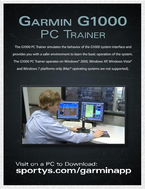
Minimum System Requirements<br />
Minimum system requirements for the <strong>G1000</strong> <strong>Trainer</strong>:<br />
1.8 GHz processor<br />
256 MB RAM<br />
Windows® 2000 or XP<br />
400 MB free hard disk space (1.4 GB free for FliteCharts option)<br />
DVD-ROM drive<br />
Microsoft® DirectX® 9.0c (software application included on the <strong>G1000</strong> <strong>Trainer</strong><br />
CD-ROM)<br />
Video Card: DirectX-capable card with a minimum of 128 MB of memory and<br />
video card drivers that support DirectX 9.0c<br />
Screen resolution: 1280 pixels wide x 1024 pixels high<br />
Optional: Four-axis joystick with throttle/power and rudder control<br />
Optional: Sound Card<br />
Minimum system requirements for Dual Screen mode:<br />
2.0 GHz processor<br />
512 MB RAM<br />
Windows® 2000 or XP<br />
400 MB free hard disk space (1.4 GB free for FliteCharts option)<br />
DVD-ROM drive<br />
Microsoft® DirectX® 9.0c (software application included on the <strong>G1000</strong> <strong>Trainer</strong><br />
CD-ROM)<br />
Video Card: DirectX-capable card with a minimum of 256 MB of memory and<br />
video card drivers that support DirectX 9.0c<br />
Screen resolution: 1280 pixels wide x 1024 pixels high<br />
Optional: Four-axis joystick with throttle/power and rudder control<br />
Optional: Sound Card