AXIS 209MFD - User's Manual - Axis Communications
AXIS 209MFD - User's Manual - Axis Communications
AXIS 209MFD - User's Manual - Axis Communications
- No tags were found...

You also want an ePaper? Increase the reach of your titles
YUMPU automatically turns print PDFs into web optimized ePapers that Google loves.
<strong>AXIS</strong> <strong>209MFD</strong>/MFD-R/MFD-R M12Fixed Dome Network CameraUser’s <strong>Manual</strong>
About this DocumentThis manual is intended for administrators and users of the <strong>AXIS</strong> <strong>209MFD</strong>Network Camera, and is applicable for software release 4.45 and later. Itincludes instructions for using and managing the camera on your network.Previous experience of networking will be of use when using this product.Some knowledge of UNIX or Linux-based systems may also be beneficial, fordeveloping shell scripts and applications. Later versions of this document willbe posted to the <strong>Axis</strong> Website, as required. See also the product’s online help,available via the Web-based interface.Safety Notices Used In This <strong>Manual</strong>Caution! - Indicates a potential hazard that can damage the product.Important! - Indicates a hazard that can seriously impair operation.Do not proceed beyond any of the above notices until you have fullyunderstood the implications.Intellectual Property Rights<strong>Axis</strong> AB has intellectual property rights relating to technology embodied inthe product described in this document. In particular, and without limitation,these intellectual property rights may include one or more of the patents listedat http://www.axis.com/patent.htm and one or more additional patents orpending patent applications in the US and other countries.This product contains licensed third-party software. See the menu item“About” in the product’s user interface for more information.This product contains source code copyright Apple Computer, Inc., under theterms of Apple Public Source License 2.0 (seehttp://www.opensource.apple.com/apsl/).The source code is available from:http://developer.apple.com/darwin/projects/bonjour/Legal ConsiderationsVideo and audio surveillance can be prohibited by laws that vary from countryto country. Check the laws in your local region before using this product forsurveillance purposes.This product includes one (1) MPEG-4 decoder license. To purchase furtherlicenses, contact your reseller.Electromagnetic Compatibility (EMC)This equipment generates, uses and can radiate radio frequency energy and, ifnot installed and used in accordance with the instructions, may cause harmfulinterference to radio communications. However, there is no guarantee thatinterference will not occur in a particular installation.If this equipment causes harmful interference to radio or television reception,which can be determined by turning the equipment off and on, the user isencouraged to try to correct the interference by one or more of the followingmeasures: Re-orient or relocate the receiving antenna. Increase the separationbetween the equipment and receiver. Connect the equipment to an outlet on adifferent circuit to the receiver. Consult your dealer or an experiencedradio/TV technician for help. Shielded (STP) network cables must be used withthis unit to ensure compliance with EMC standards.USA - This equipment has been tested and found to comply with the limitsfor a Class B computing device pursuant to Subpart B of Part 15 of FCC rules,which are designed to provide reasonable protection against such interferencewhen operated in a commercial environment. Operation of this equipment in aresidential area is likely to cause interference, in which case the user at his/herown expense will be required to take whatever measures may be required tocorrect the interference.Canada - This Class B digital apparatus complies with Canadian ICES-003.Europe - This equipment is not connected to immunity related functionsin motor vehicles. It fulfills the requirements of the EMC directive taking intoaccount the automotive environment. This digital equipment fulfills therequirements for radiated emission according to limit B of EN55022, and therequirements for immunity according to EN55024 residential, commercial, andlight industry.Japan - This is a class B product based on the standard of the VoluntaryControl Council for Interference from Information Technology Equipment(VCCI). If this is used near a radio or television receiver in a domesticenvironment, it may cause radio interference. Install and use the equipmentaccordinginstructionQuickmanual.User’s GuideAustralia - This electronic device meets the requirements of the Radiocommunications (Electromagnetic Compatibility) Standard AS/NZS CISPR22.Equipment ModificationsThis equipment must be installed and used in strict accordance with theinstructions given in the user documentation. This equipment contains nouser-serviceable components. Unauthorized equipment changes ormodifications will invalidate all applicable regulatory certifications andapprovals.LiabilityEvery care has been taken in the preparation of this manual. Please informyour local <strong>Axis</strong> office of any inaccuracies or omissions. <strong>Axis</strong> <strong>Communications</strong>AB cannot be held responsible for any technical or typographical errors andreserves the right to make changes to the product and manuals without priornotice. <strong>Axis</strong> <strong>Communications</strong> AB makes no warranty of any kind with regardto the material contained within this document, including, but not limited to,the implied warranties of merchantability and fitness for a particular purpose.<strong>Axis</strong> <strong>Communications</strong> AB shall not be liable nor responsible for incidental orconsequential damages in connection with the furnishing, performance or useof this material.Trademark AcknowledgmentsApple, Boa, Bonjour, Ethernet, Internet Explorer, Linux, Microsoft, Mozilla,Netscape Navigator, OS/2, Real, QuickTime, UNIX, Windows, WWW areregistered trademarks of the respective holders. Java and all Java-basedtrademarks and logos are trademarks or registered trademarks of SunMicrosystems, Inc. in the United States and other countries. <strong>Axis</strong><strong>Communications</strong> AB is independent of Sun Microsystems Inc.UPnP TM is a certification mark of the UPnP TM Implementers Corporation.SupportShould you require any technical assistance, please contact your <strong>Axis</strong> reseller.If your questions cannot be answered immediately, your reseller will forwardyour queries through the appropriate channels to ensure a rapid response. Ifyou are connected to the Internet, you can:• download user documentation and firmware updates• find answers to resolved problems in the FAQ database. Search by product,category, or phrases• report problems to <strong>Axis</strong> support by logging in to your private support area• visit <strong>Axis</strong> Support at www.axis.com/techsup/WEEE DirectiveThe European Union has enacted a Directive 2002/96/EC on WasteElectrical and Electronic Equipment (WEEE Directive). This directiveis applicable in the European Union member states.The WEEE marking on this product (see right) or its documentationindicates that the product must not be disposed of together withhousehold waste. To prevent possible harm to human health and/or theenvironment, the product must be disposed of in an approved andenvironmentally safe recycling process. For further information on how todispose of this product correctly, contact the product supplier, or the localauthority responsible for waste disposal in your area.Business users should contact the product supplier for information on how todispose of this product correctly. This product should not be mixed with othercommercial waste.<strong>AXIS</strong> <strong>209MFD</strong> User’s <strong>Manual</strong> Rev 3.0September 2008Part No: 32988Copyright© <strong>Axis</strong> <strong>Communications</strong> AB, 2007 - 2008
<strong>AXIS</strong> <strong>209MFD</strong>/MFD-R/MFD-R M123ContentsProduct overview . . . . . . . . . . . . . . . . . . . . . . . . . . . . . . . . . . . . . . . . . . . . . . . . . . . . . . . . . . . . . . . . . . . . . . . . . . . . . . . 5Key features . . . . . . . . . . . . . . . . . . . . . . . . . . . . . . . . . . . . . . . . . . . . . . . . . . . . . . . . . . . . . . . . . . . . . . . 5Overview . . . . . . . . . . . . . . . . . . . . . . . . . . . . . . . . . . . . . . . . . . . . . . . . . . . . . . . . . . . . . . . . . . . . . . . . . . 6LED indicators . . . . . . . . . . . . . . . . . . . . . . . . . . . . . . . . . . . . . . . . . . . . . . . . . . . . . . . . . . . . . . . . . . . . . . 7Accessing the Camera . . . . . . . . . . . . . . . . . . . . . . . . . . . . . . . . . . . . . . . . . . . . . . . . . . . . . . . . . . . . . . . . . . . . . . . . . . . 8Access from a browser . . . . . . . . . . . . . . . . . . . . . . . . . . . . . . . . . . . . . . . . . . . . . . . . . . . . . . . . . . . . . . . 8<strong>AXIS</strong> Media Control . . . . . . . . . . . . . . . . . . . . . . . . . . . . . . . . . . . . . . . . . . . . . . . . . . . . . . . . . . . . . . . . . . 8Setting the root password . . . . . . . . . . . . . . . . . . . . . . . . . . . . . . . . . . . . . . . . . . . . . . . . . . . . . . . . . . . . . 9Accessing the camera from the Internet . . . . . . . . . . . . . . . . . . . . . . . . . . . . . . . . . . . . . . . . . . . . . . . . . . 9The Live View page . . . . . . . . . . . . . . . . . . . . . . . . . . . . . . . . . . . . . . . . . . . . . . . . . . . . . . . . . . . . . . . . . . 9Pan/Tilt/Zoom controls . . . . . . . . . . . . . . . . . . . . . . . . . . . . . . . . . . . . . . . . . . . . . . . . . . . . . . . . . . . . . . 10The control panel . . . . . . . . . . . . . . . . . . . . . . . . . . . . . . . . . . . . . . . . . . . . . . . . . . . . . . . . . . . . . . . . . . 10Video Streams . . . . . . . . . . . . . . . . . . . . . . . . . . . . . . . . . . . . . . . . . . . . . . . . . . . . . . . . . . . . . . . . . . . . . . . . . . . . . . . . 11How to stream MPEG-4 . . . . . . . . . . . . . . . . . . . . . . . . . . . . . . . . . . . . . . . . . . . . . . . . . . . . . . . . . . . . . 11MPEG-4 clients . . . . . . . . . . . . . . . . . . . . . . . . . . . . . . . . . . . . . . . . . . . . . . . . . . . . . . . . . . . . . . . . . . . . 12Motion JPEG . . . . . . . . . . . . . . . . . . . . . . . . . . . . . . . . . . . . . . . . . . . . . . . . . . . . . . . . . . . . . . . . . . . . . . 12Configuration . . . . . . . . . . . . . . . . . . . . . . . . . . . . . . . . . . . . . . . . . . . . . . . . . . . . . . . . . . . . . . . . . . . . . . . . . . . . . . . . . 13Accessing the Setup link . . . . . . . . . . . . . . . . . . . . . . . . . . . . . . . . . . . . . . . . . . . . . . . . . . . . . . . . . . . . . 13Video & Image settings . . . . . . . . . . . . . . . . . . . . . . . . . . . . . . . . . . . . . . . . . . . . . . . . . . . . . . . . . . . . . . . . . . . . . . . . . 14Image . . . . . . . . . . . . . . . . . . . . . . . . . . . . . . . . . . . . . . . . . . . . . . . . . . . . . . . . . . . . . . . . . . . . . . . . . . . 14Overlay/Mask . . . . . . . . . . . . . . . . . . . . . . . . . . . . . . . . . . . . . . . . . . . . . . . . . . . . . . . . . . . . . . . . . . . . . . 15Advanced . . . . . . . . . . . . . . . . . . . . . . . . . . . . . . . . . . . . . . . . . . . . . . . . . . . . . . . . . . . . . . . . . . . . . . . . 16MPEG-4 Settings . . . . . . . . . . . . . . . . . . . . . . . . . . . . . . . . . . . . . . . . . . . . . . . . . . . . . . . . . . . . . . . . . . . 17MJPEG Settings . . . . . . . . . . . . . . . . . . . . . . . . . . . . . . . . . . . . . . . . . . . . . . . . . . . . . . . . . . . . . . . . . . . . 18Live View Config . . . . . . . . . . . . . . . . . . . . . . . . . . . . . . . . . . . . . . . . . . . . . . . . . . . . . . . . . . . . . . . . . . . . . . . . . . . . . . 19Layout . . . . . . . . . . . . . . . . . . . . . . . . . . . . . . . . . . . . . . . . . . . . . . . . . . . . . . . . . . . . . . . . . . . . . . . . . . . 19HTML Examples . . . . . . . . . . . . . . . . . . . . . . . . . . . . . . . . . . . . . . . . . . . . . . . . . . . . . . . . . . . . . . . . . . . . 20External Video . . . . . . . . . . . . . . . . . . . . . . . . . . . . . . . . . . . . . . . . . . . . . . . . . . . . . . . . . . . . . . . . . . . . . 21Sequence Mode . . . . . . . . . . . . . . . . . . . . . . . . . . . . . . . . . . . . . . . . . . . . . . . . . . . . . . . . . . . . . . . . . . . . 21PTZ Configuration . . . . . . . . . . . . . . . . . . . . . . . . . . . . . . . . . . . . . . . . . . . . . . . . . . . . . . . . . . . . . . . . . . . . . . . . . . . . . 22Preset Position Setup . . . . . . . . . . . . . . . . . . . . . . . . . . . . . . . . . . . . . . . . . . . . . . . . . . . . . . . . . . . . . . . 22Guard Tour . . . . . . . . . . . . . . . . . . . . . . . . . . . . . . . . . . . . . . . . . . . . . . . . . . . . . . . . . . . . . . . . . . . . . . . 23Advanced . . . . . . . . . . . . . . . . . . . . . . . . . . . . . . . . . . . . . . . . . . . . . . . . . . . . . . . . . . . . . . . . . . . . . . . . 23Event Config . . . . . . . . . . . . . . . . . . . . . . . . . . . . . . . . . . . . . . . . . . . . . . . . . . . . . . . . . . . . . . . . . . . . . . . . . . . . . . . . . . 24Event Servers . . . . . . . . . . . . . . . . . . . . . . . . . . . . . . . . . . . . . . . . . . . . . . . . . . . . . . . . . . . . . . . . . . . . . . 24Event Types . . . . . . . . . . . . . . . . . . . . . . . . . . . . . . . . . . . . . . . . . . . . . . . . . . . . . . . . . . . . . . . . . . . . . . . 24Triggered Events . . . . . . . . . . . . . . . . . . . . . . . . . . . . . . . . . . . . . . . . . . . . . . . . . . . . . . . . . . . . . . . . . . . 24Scheduled Event . . . . . . . . . . . . . . . . . . . . . . . . . . . . . . . . . . . . . . . . . . . . . . . . . . . . . . . . . . . . . . . . . . . 25Camera Tampering . . . . . . . . . . . . . . . . . . . . . . . . . . . . . . . . . . . . . . . . . . . . . . . . . . . . . . . . . . . . . . . . . 26Motion Detection . . . . . . . . . . . . . . . . . . . . . . . . . . . . . . . . . . . . . . . . . . . . . . . . . . . . . . . . . . . . . . . . . . 26System Options . . . . . . . . . . . . . . . . . . . . . . . . . . . . . . . . . . . . . . . . . . . . . . . . . . . . . . . . . . . . . . . . . . . . . . . . . . . . . . . 28Security . . . . . . . . . . . . . . . . . . . . . . . . . . . . . . . . . . . . . . . . . . . . . . . . . . . . . . . . . . . . . . . . . . . . . . . . . . 28Date & Time . . . . . . . . . . . . . . . . . . . . . . . . . . . . . . . . . . . . . . . . . . . . . . . . . . . . . . . . . . . . . . . . . . . . . . 29Network - Basic TCP/IP Settings . . . . . . . . . . . . . . . . . . . . . . . . . . . . . . . . . . . . . . . . . . . . . . . . . . . . . . . 29Network - Advanced TCP/IP Settings . . . . . . . . . . . . . . . . . . . . . . . . . . . . . . . . . . . . . . . . . . . . . . . . . . . . 30LED Settings . . . . . . . . . . . . . . . . . . . . . . . . . . . . . . . . . . . . . . . . . . . . . . . . . . . . . . . . . . . . . . . . . . . . . . 33Maintenance . . . . . . . . . . . . . . . . . . . . . . . . . . . . . . . . . . . . . . . . . . . . . . . . . . . . . . . . . . . . . . . . . . . . . . 33Support . . . . . . . . . . . . . . . . . . . . . . . . . . . . . . . . . . . . . . . . . . . . . . . . . . . . . . . . . . . . . . . . . . . . . . . . . . 33Advanced . . . . . . . . . . . . . . . . . . . . . . . . . . . . . . . . . . . . . . . . . . . . . . . . . . . . . . . . . . . . . . . . . . . . . . . . 34About . . . . . . . . . . . . . . . . . . . . . . . . . . . . . . . . . . . . . . . . . . . . . . . . . . . . . . . . . . . . . . . . . . . . . . . . . . . 34Resetting to the factory default settings . . . . . . . . . . . . . . . . . . . . . . . . . . . . . . . . . . . . . . . . . . . . . . . . . 34Unit connectors . . . . . . . . . . . . . . . . . . . . . . . . . . . . . . . . . . . . . . . . . . . . . . . . . . . . . . . . . . . . . . . . . . . . 35
<strong>AXIS</strong> <strong>209MFD</strong>/MFD-R/MFD-R M124Troubleshooting . . . . . . . . . . . . . . . . . . . . . . . . . . . . . . . . . . . . . . . . . . . . . . . . . . . . . . . . . . . . . . . . . . . . . . . . . . . . . . . 36Technical Specifications . . . . . . . . . . . . . . . . . . . . . . . . . . . . . . . . . . . . . . . . . . . . . . . . . . . . . . . . . . . . . . . . . . . . . . . . 40Optimizing your system . . . . . . . . . . . . . . . . . . . . . . . . . . . . . . . . . . . . . . . . . . . . . . . . . . . . . . . . . . . . . . 42Bandwidth . . . . . . . . . . . . . . . . . . . . . . . . . . . . . . . . . . . . . . . . . . . . . . . . . . . . . . . . . . . . . . . . . . . . . . . . 42Glossary of Terms . . . . . . . . . . . . . . . . . . . . . . . . . . . . . . . . . . . . . . . . . . . . . . . . . . . . . . . . . . . . . . . . . . . . . . . . . . . . . . 44Index . . . . . . . . . . . . . . . . . . . . . . . . . . . . . . . . . . . . . . . . . . . . . . . . . . . . . . . . . . . . . . . . . . . . . . . . . . . . . . . . . . . . . . . . 49
<strong>AXIS</strong> <strong>209MFD</strong>/MFD-R/MFD-R M125Product overviewThe <strong>AXIS</strong> <strong>209MFD</strong>/MFD-R/MFD-R M12 Fixed Dome Network Camera is a high-performance,progressive-scan camera that is ideally suited for office and business locations. It has a 1.3 megapixelsensor providing more than three times better resolution compared to a high-resolution analog camera. Ithas a discreet, compact casing that effectively protects against tampering, and is easy to mount.Multi-window motion detection and simultaneous Motion JPEG and MPEG-4 allow for optimization bothon image quality and bandwidth efficiency. The frame rate can be up to 12 fps at 1280 x 1024 (MotionJPEG), and 8 frames per second at 1280 x 1024 (MPEG-4).Multi-level password protection, IP-address filtering and HTTPS encryption ensure network security. Powerover Ethernet reduces cabling requirements and enables centralized power back up. Supported by theindustry's largest base of surveillance applications, the <strong>AXIS</strong> <strong>209MFD</strong>/MFD-R/MFD-R M12 is the perfectsolution for securing shops, hotel receptions and corridors.Key features• Discreet and compact design, effectively protecting against tampering/vandalisation• More than three times better resolution compared to a high-resolution analog camera• Progressive scan technology providing full resolution images of moving objects, with no distortion• Simultaneous Motion JPEG and MPEG-4 for optimized quality and bandwidth• Power over Ethernet for reduced cabling and consolidated power• Multi-window motion detection with alarm image buffering• Quick, easy and flexible mounting on ceilings or walls.
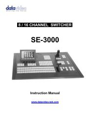
<strong>AXIS</strong> <strong>209MFD</strong>/MFD-R/MFD-R M126OverviewFront view39mmRear viewPosition of rear cableexit (optional)Side viewBase plate∅102mmScrew holes∅100mmProduct ID & Serialnumber (S/N) labelScrew holeScrew holeNetwork cable withconnectorScrew holeScrew holeIndicator LEDsControl buttonDimensionsDiameter 1 = 102mm (4.02”), Diameter 2 = 100mm (3.94”)Height = 39mm (1.54”)Weight = 0.18 kg (0.40lb)
<strong>AXIS</strong> <strong>209MFD</strong>/MFD-R/MFD-R M127Control Button - Press this button to install the camera using the <strong>AXIS</strong> Internet Dynamic DNS Service, or torestore the factory default settings, as described in Resetting to the factory default settings, on page 34.LED indicatorsLED Color DescriptionNetwork Green Steady for connection to 100 Mbit/s network. Flashes for network activity.Amber Steady for connection to 10 Mbit/s network. Flashes for network activity.Unlit No connection.Status Green Shows steady green for normal operation.Note: The Status LED can be configured to be unlit during normal operation, or to flashonly when the camera is accessed. See the online help files for more information. Go toSetup > System Options > LED settings.Amber Steady during startup, reset to factory default or when restoring settings.Red Slow flash for failed upgrade.Power Green Normal operation.Amber Flashes green/amber during firmware upgrade.
<strong>AXIS</strong> <strong>209MFD</strong>/MFD-R/MFD-R M128Accessing the CameraYou must install the network camera before you can access it. To install the camera, please see theinstallation guide supplied with the product.The camera can be used with most operating systems and browsers. The recommended browser is MicrosoftInternet Explorer with Windows, Safari with Macintosh and Firefox with other operating systems.Notes: • To view streaming video in Microsoft Internet Explorer, set your browser to allow ActiveX controls and allow the <strong>AXIS</strong> MediaControl (AMC - on page 8) to be installed on your computer.• QuickTime TM and Real Player TM are also supported for viewing streaming MPEG-4 video and audio.• If your computer restricts the use of additional software components, it is also possible to use the Firefox browser which does notrequire extra components.• The <strong>AXIS</strong> <strong>209MFD</strong> includes one (1) decoder license for viewing MPEG-4 video streams. This is automatically installed with AMC.The administrator can disable the installation of the MPEG-4 decoder, to prevent unlicensed copies being installed. Furtherlicenses are available from your <strong>Axis</strong> dealer.Access from a browser1. Start a browser (Internet Explorer, Firefox)2. Enter the IP address or host name of the camera in theLocation/Address field of your browser.To access the camera from a Macintosh computer (Mac OSX), just click on the Bonjour tab and selectthe <strong>AXIS</strong> <strong>209MFD</strong>/MFD-R/MFD-R M12 from the drop-down list.3. If this is the first time you are accessing the camera, see Setting the root password, on page 9.Otherwise enter your user name and password, as set by the administrator.4. The camera’s Live View page is now displayed in your browser.Note: The layout of the Live View page may have been customized to specific requirements. Consequently, some of the examples andfunctions featured here may differ from those displayed on your own Live View page.<strong>AXIS</strong> Media ControlThe <strong>AXIS</strong> Media Control (AMC) is installed automatically the first time the camera is accessedfrom Microsoft Internet Explorer. The AMC control panel is used to configure various video settings,and can be opened by right-clicking on the video image in the Live View web page. Pleasesee the readme file included in the tool for more information.
<strong>AXIS</strong> <strong>209MFD</strong>/MFD-R/MFD-R M129Setting the root password1. When accessing the camera for the first time, the‘Configure Root Password’ dialog appears on thescreen.Note: Before you enter your password at this point, you can secure configurationof the root password via HTTPS by creating a self-signed certificate.To do so, click the Create self-signed certificate... button in theCreate Certificate window, and then proceed as follows.2. Enter a password and then re-enter it, to confirmthe spelling. Click OK.3. The ‘Enter Network Password’ dialog appears. Enterthe User name: rootNote: The default administrator user name root is permanent and cannot be deleted or altered.4. Enter the password as set in step 2 above, and click OK. If the password is lost, the camera must bereset to the factory default settings. See Resetting to the factory default settings, on page 34.5. If required, click Yes to install the <strong>AXIS</strong> Media Control (AMC). You will need administrator rightson the computer to do this.Accessing the camera from the InternetOnce installed, the camera is accessible on your local network (LAN). To access the camera from the Internetyou must configure your broadband router to allow incoming data traffic to the camera. To do this, enablethe NAT-traversal feature, which will attempt to automatically configure the router to allow access to thecamera. This is enabled from Setup > System Options > Network > TCP/IP Advanced.For more information, please see NAT traversal (port mapping) for IPv4, on page 30. See also the <strong>AXIS</strong>Internet Dynamic DNS Service at www.axiscam.net or, for technical notes on this and other topics, visit the<strong>Axis</strong> Support Web at www.axis.com/techsupThe Live View pageAll the buttons described below may not be visible depending on how the Live View Page has beencustomized.The Video format drop-down list allows the video format on the Live View page to betemporarily changed.The manual Trigger button can trigger an event directly from the Live View page. Thisis configured from Setup > Live View Config > Layout.The Snapshot button saves a snapshot of the video image currently displayed.Right-click on the video image to save it in JPEG format on your computer. This buttonis primarily intended for use when the AMC viewer toolbar is not available.If you have Video Format set to Motion JPEG, you can use the View Size buttons toeither reduce the image to 800 pixels in width or return the image to full scale. To viewthe View Size buttons, Setup > Video & Image > Resolution must be set to greater than800 x 600 pixels.The AMC (<strong>AXIS</strong> Media Control) viewer toolbar is available in Microsoft Internet Explorer only. Itdisplays the following buttons:The Play/Stop button starts and stops the live video stream.The Snapshot button saves a snapshot of the video image displayed. The Snapshotfunction and the target directory for saving snapshots can be configured from the AMCControl Applet in the Windows Control Panel (Internet Explorer only).
<strong>AXIS</strong> <strong>209MFD</strong>/MFD-R/MFD-R M1210Click the View Full Screen button to make the video image fill the entire screen area.Press Esc (Escape) on the computer keyboard to exit full screen.Click the Record button to start an MPEG-4 recording (only available when viewingMPEG-4).These buttons change the navigation mode. Selecting Center will move the camera viewto center on the position that was clicked. Joystick mode will move the camera in thedirection indicated by a mouse click, relative to the center of the image. The farther youclick on the image from the center, the greater the movement. These modes can also beselected by right-clicking in the image.Note: The snapshot function in MPEG-4 full screen mode will return the image view to the default live viewpage. Click the View Full Screen button to return to Full Screen Mode.Pan/Tilt/Zoom controlsThe <strong>AXIS</strong> <strong>209MFD</strong> can be controlled by clicking in the image, or by clicking on thePan/Tilt/Zoom bars on the Live View page. These are enabled/disabled for specified users bythe administrator under System Options > Security > Users > User List.Zoom out to overview image will set the camera to the minimum zoom position. Note thatwhen in this position, the camera cannot pan or tilt.Note: Digital PTZ is not enabled by default. To use digital PTZ and access these controls as well as the Control panel, see PTZ Configuration,on page 22.The control panelClick the Ctrl panel button to display the control panel. The panel provides buttonsfor switching between Pan, Tilt and Zoom Functions when in Center mode. Thiscontrols whether the camera should pan/tilt to the position in the image that wasclicked, or whether it should zoom directly in on that point.The control panel can also show your own shortcut buttons, which are configuredfrom Setup > PTZ Configuration > Advanced.Note: The scroll wheel on the mouse can also be used to control the zoom.
<strong>AXIS</strong> <strong>209MFD</strong>/MFD-R/MFD-R M1211Video StreamsThe <strong>AXIS</strong> <strong>209MFD</strong>/MFD-R/MFD-R M12 provides several different image and video stream formats. Thetype you want to use would depend on your requirements and on the properties of your network.The Live View page provides access to MPEG-4 and Motion JPEG video streams, as well as to single JPEGimages. Other applications and clients can also access these video streams/images directly, without goingvia the Live View page.How to stream MPEG-4This video compression standard makes good use of bandwidth, and can provide DVD-quality video streamsat less than 1 Mbit/s. Note that the image settings of the MPEG-4 stream are the same for all clients.Deciding on the combination of protocols and methods to use depends on your viewing requirements, andon the properties of your network. The options available in AMC (see page 12) are:Unicast RTPRTP over RTSPRTP over RTSP over HTTPThis unicast method (RTP over UDP)should be your first consideration for liveunicast video, especially when it isimportant to always have an up-to-datevideo stream, even if some images aredropped.This unicast method (RTP tunneled overRTSP) is useful as it is relatively simple toconfigure firewalls to allow RTSP traffic.This unicast method can be used totraverse firewalls. Firewalls are commonlyconfigured to allow the HTTP protocol,thus allowing RTP to be tunneled.Unicasting is used for video-on-demand broadcasting, so that there is no videotraffic on the network until a client connects and requests the stream.Note that there is a maximum of 10 simultaneous unicast connections.Multicast RTPThis method (RTP over UDP) should be used for live multicast video. The video stream is always up-to-date, even if someimages are dropped.Multicasting provides the most efficient usage of bandwidth when there are large numbers of clients viewing simultaneously.A multicast broadcast cannot however, pass a network router unless the router is configured to allow this. It is thus not possibleto multicast over the Internet, for example.Note also that all multicast viewers count as one unicast viewer in the maximum total of 10 simultaneous connections.AMC will negotiate with the camera to determine exactly which transport protocol to use in the order listedabove. This order can be changed and the options disabled, to suit specific requirements.Important!MPEG-4 is licensed technology. The <strong>AXIS</strong> <strong>209MFD</strong>/MFD-R/MFD-R M12 includes one viewing clientlicense. Installing additional unlicensed copies of the viewing client is prohibited. To purchase additionallicenses, contact your <strong>Axis</strong> reseller.
<strong>AXIS</strong> <strong>209MFD</strong>/MFD-R/MFD-R M1212MPEG-4 clients<strong>AXIS</strong> Media Control (AMC)The recommended method of accessing live video (MPEG-4 andMotion JPEG) from the <strong>AXIS</strong> <strong>209MFD</strong>/MFD-R/MFD-R M12 is touse the <strong>AXIS</strong> Media Control (AMC) in Microsoft Internet Explorerin Windows.The AMC control panel can be used to configure various video andaudio settings. Please see the readme file included in the tool formore information.The AMC control panel is automatically installed on first use, afterwhich it can be configured.Open the AMC Control Panel from:• Windows Control Panel (from the Start menu)• Alternatively, right-click the video image and click Settings inthe menu.QuickTime & Real PlayerTo access the video stream from QuickTime or Real Player the following path can be used:rtsp:///mpeg4/media.ampNotes: • The <strong>AXIS</strong> <strong>209MFD</strong> supports QuickTime 6.5.1 (or later) and Real Player 10.5 (or later)• QuickTime adds latency to the video and audio stream (up to 3 seconds)• It may be possible to use other players to view the MPEG-4 stream using the paths above, although this is not guaranteed by <strong>Axis</strong>• = IP addressMotion JPEGThis format uses standard JPEG still images for the video stream. These images are then displayed andupdated at a rate sufficient to create a stream that shows constantly updated motion.The Motion JPEG stream uses considerable amounts of bandwidth, but provides excellent image quality andaccess to every image contained in the stream. The recommended method of accessing Motion JPEG livevideo from the <strong>AXIS</strong> <strong>209MFD</strong>/MFD-R/MFD-R M12 is to use the <strong>AXIS</strong> Media Control (AMC) in MicrosoftInternet Explorer in Windows.Note also that multiple clients accessing Motion JPEG streams can use different image settings.Alternative methods of accessing the video streamVideo/images from the <strong>AXIS</strong> <strong>209MFD</strong>/MFD-R/MFD-R M12 can also be accessed in the following ways:• Motion JPEG server push (if supported by the client, e.g. Firefox). This option maintains an open HTTPconnection to the browser and sends data as and when required, for as long as required.• Still JPEG images in a browser. Enter the path: http:///axis-cgi/jpg/image.cgi?resolution=320x240• Windows Media Player. This requires the AMC and the MPEG-4 viewing client to be installed. The pathsthat can be used are listed below in the order of preference.• Unicast via RTP: axrtpu:///mpeg4/media.amp• Unicast via RTSP: axrtsp:///mpeg4/media.amp• Unicast via RTSP, tunneled via HTTP: axrtsphttp:///mpeg4/media.amp• Unicast via RTSP, tunneled via HTTPS: axrtsphttps:///mpeg4/media.amp• Multicast: axrtpm:///mpeg4/media.ampNote: = IP address
<strong>AXIS</strong> <strong>209MFD</strong>/MFD-R/MFD-R M1213ConfigurationThis section describes how to configure the camera, and is intended for product Administrators, who haveunrestricted access to all the configuration menus, and Operators, who have access to the settings for Video& Image, Audio, Live View Config and Event Configuration.The camera is configured from the Setup link, from a browser. (For supported browsers, see TechnicalSpecifications, on page 40).The descriptions below show examples of the features available in the <strong>AXIS</strong> <strong>209MFD</strong>. For details of eachsetting, please refer to the online help available from the setup link.Accessing the Setup linkFollow the instructions below to access the Setup link from a browser.1. Start your browser and enter the IP address or hostname of the camera in the location/address field.2. The Live View page appears. Click Setup to viewfurther menus.Setup
<strong>AXIS</strong> <strong>209MFD</strong>/MFD-R/MFD-R M1214Video & Image settingsImageUse these settings to change the image as required. The image can be rotated, the image resolution andcompression can be adjusted, and the white balance can be changed. The image can also be mirrored tochange the perspective.The configuration of the video image will affect the camera’s overall performance, depending on how it isused and on the available bandwidth. Setting higher resolution and lower compression improves videoimage quality, but increases the amount of bandwidth required.Note: The maximum resolution for the <strong>AXIS</strong> <strong>209MFD</strong>/MFD-R/MFD-R M12 is 1280 x 1024 pixels. If you enable digital PTZ and increaseMax zoom (See PTZ Configuration, on page 22), the maximum available resolution for the <strong>AXIS</strong> <strong>209MFD</strong> decreases. When digitalPTZ is disabled, the maximum available resolution returns to 1280 x 1024 pixels.Please see the online helpfor further information on these settings.Text Overlay SettingsThe date, time, and user-defined text can be included onone line, either on the top or bottom of the video image.It is also possible to set how the text and text backgroundare displayed. You can set the text to be either black orwhite, and the text background can also be set to black,white, semi-transparent, or transparent.Please see the online help for further information onthese settings.Text, date andtime overlayVideo StreamDefine the maximum video stream time per session in seconds, minutes or hours. When the set time hasexpired, a new stream can be started by refreshing the page in the browser. For unlimited video stream time,select the Unlimited radio button. Note that the maximum video stream time does not apply to clientsconnecting via multicast.
<strong>AXIS</strong> <strong>209MFD</strong>/MFD-R/MFD-R M1215The frame rate allowed to each viewer can also be limited, to avoid bandwidth problems on the network. Toallow the highest available frame rate, select the Unlimited radio button.For a preview of the image before saving, click Test. When satisfied with the settings, click Save. Pleasenote that the preview image will be in JPEG format, even though the settings are valid both for MotionJPEG and MPEG-4.Overlay/MaskOverlay/Mask SettingsWhen using an image overlay, selectfrom the following options the type youwant to use:• Uploaded image as overlay - usuallyused to provide extra information inthe video image.• Uploaded image as privacy mask -conceals part of the video image.• Configurable areas as privacy masks -up to three black areas are used toconceal parts of the video image.The difference between an overlay and aprivacy mask is that a privacy maskcannot be bypassed by accessing thevideo stream with the help of the <strong>AXIS</strong> HTTP API, whereas an overlay can.Selecting the overlay/mask type will display further settings available for the selected type. See the onlinehelp for further information.Overlay/Mask TypeText, date andtime overlaysOverlay imageWhen using an image overlay, select the type from the following options:• Uploaded image as overlay - usually used to provide extra information in the video image.• Configurable areas as privacy mask - up to three areas are used to conceal parts of the video image.The difference between an overlay and a privacy mask is that a privacy mask cannot be bypassed byaccessing the video stream with the help of the VAPIX® API, whereas an overlay can.Selecting the overlay/mask type will display further settings available for the selected type. See the onlinehelp for further information.Upload and use an overlay/maskTo upload an overlay image/privacy mask to the camera:1. Select the type of overlay in Overlay/Mask Type field.2. In the Upload own image field, click the Browse button and locate the image file on yourcomputer or server.3. Click the Upload button and follow the on-screen instructions.To use an already uploaded image:1. Select an uploaded image from the Use image drop-down list.2. Place the image at the required location by entering the x and y coordinates (0,0 being the upperleft corner).3. Click Save.
<strong>AXIS</strong> <strong>209MFD</strong>/MFD-R/MFD-R M1216Overlay image requirementsImage FormatsThere are a number of limitations when using overlay images, such as the size and positioning of images.Please refer to the online help for more information.AdvancedCamera SettingsImage Size• Windows 24-bit BMP (full color) The height and width of the overlay image inpixels must be exactly divisible by 4.• Windows 4-bit BMP (16 colors) The height and width of the overlay image inpixels must be divisible by 16.These settings enable you to fine-tune the video image.Lighting ConditionsTo compensate for the lighting Conditions, the Color level, Brightness, Sharpness, and the ExposureControl and Exposure area can all be adjusted.The Exposure area is used to determine which part of the image will be used to calculate the exposure.Low Light BehaviorExposure priority defines the balance between image quality and the frame rate. Higher image quality mayreduce frame rate and increase motion blur. A prioritized frame rate may instead increase image noise.Depending on your requirements, use this to prioritize the image quality or the frame rate.You can view the image after saving. Please refer to the online help for more information .
<strong>AXIS</strong> <strong>209MFD</strong>/MFD-R/MFD-R M1217MPEG-4 SettingsHere you can adjust the MPEG-4 settings and control the video bit rate.GOV SettingsThe GOV structure describes the composition of the MPEG-4 video stream. Setting the GOV-length to a highvalue saves considerably on bandwidth. The Cyclic refresh parameter gives a smoother bit rate and can beuseful if bandwidth is limited.Bit Rate ControlLimiting the maximum bit rate is a good way of controlling the bandwidth used by the MPEG-4 videostream. Leaving the Maximum bit rate as Unlimited will provide consistently good image quality, but at theexpense of increased bandwidth usage whenever there is more activity in the image. Limiting the bit rate toa defined value will prevent excessive bandwidth usage, but images will be lost when the limit is exceeded.Note that a maximum bit rate can be used for both variable and constant bit rates.The bit rate type can be set as Variable Bit Rate (VBR) or Constant Bit Rate (CBR). VBR will adjust the bitrate according to the images' complexity, thus using a lot of bandwidth for a lot of activity in the imageand less for lower activity in the monitored area.CBR allows you to set a fixed Target bit rate that will consume a predictable amount of bandwidth, andwhich will not change whatever happens in the image.As the bit rate would usually need to increase for increased image activity, but in this case cannot, theframe rate and image quality will be affected negatively. To go some of the way towards compensating forthis, it is possible to prioritize either the frame rate or the image quality whenever the bit rate wouldnormally need to be increased. Not setting a priority means the frame rate and image quality will beaffected more or less equally.
<strong>AXIS</strong> <strong>209MFD</strong>/MFD-R/MFD-R M1218MJPEG SettingsThe MJPEG Settings window is used to control the frame size of the video stream in order to improve eitherimage quality or save bandwidth.Frame Size Control - Use Frame Size Control to set the maximum frame size to unlimited for best imagequality, or to a limited number of Kilobytes. The default is set to unlimited.Preview Image Settings - Use Preview Image Settings to view the current compression and frame sizesettings in the text overlay on the top of the image.
<strong>AXIS</strong> <strong>209MFD</strong>/MFD-R/MFD-R M1219Live View ConfigLayoutThe settings on this page allowyou to decide the layout of theLive View page. You can forexample, include actionbuttons, decide the defaultvideo format, and the defaultviewer.Default Video FormatSelect the default video formatto use on the Live View page.The Show video formatselection box option displays adrop-down list on the LiveView page allowing you totemporarily change the format.When using MPEG-4 as thevideo format, the defaultviewer is <strong>AXIS</strong> Media Controlwith Internet Explorer.Note: It is also possible to view MotionJPEG when MPEG-4 is chosen asdefault and vice versa.Default ViewerFrom the drop-down lists,select the default method for viewing video images for your browser. The camera will attempt to show thevideo images in the selected video format and viewer. If this is not possible, the camera will override thesettings and select the best available combination.Browser Viewer DescriptionAMC Recommended viewer in Windows Internet Explorer (MPEG-4 /Motion JPEG).QuickTime MPEG-4 only.Windows Java applet A slower imaging alternative to AMC. Requires one of the following installed on the client:Internet Explorer• JVM (J2SE) 1.4.2 or higher• JRE (J2SE) 5.0 or higherStill image Displays still images only. Hit the Refresh button in your browser to view a new image.Server Push Recommended viewer for other browsers (Motion JPEG).Other browsersQuickTime MPEG-4 only.Java applet A slower imaging alternative to Server Push (Motion JPEG only).Still image Displays still images only. Hit the Refresh button in your browser to view a new image.Viewer SettingsShow viewer toolbar - Select this option to display the viewer you wish; for example, the <strong>AXIS</strong> MediaControl (AMC) or the QuickTime viewer toolbar under the video image in your browser.Enable MPEG-4 decoder installation - The administrator can disable the installation of the MPEG-4 decoderincluded with AMC. This is used to prevent the installation of unlicensed copies. Further decoder licensescan be purchased from your <strong>Axis</strong> dealer.
<strong>AXIS</strong> <strong>209MFD</strong>/MFD-R/MFD-R M1220Show crosshair in PTZ joystick mode - Select this option to show a red position indicator on the live viewpage when joystick navigation mode is selected.Use PTZ joystick mode as default - Sets the PTZ mode to joystick, which can be changed temporarily onthe PTZ Control Panel; but this will default to joystick if this is selected.Enable recording button - This will display the button for starting MPEG-4 recordings directly from the LiveView page.Action ButtonsThe manual trigger button can be used to manually trigger and stop an event from the Live View page. SeeEvent Config, on page 24.Enabling the display of the Snapshot button allows users to save a snapshot from the video stream byclicking the button. This button is mainly intended for use with browsers other than Internet Explorer, orwhen otherwise not using <strong>AXIS</strong> Media Control (AMC) to view the video stream. AMC (an ActiveX control)for Internet Explorer provides its own snapshot button.User Defined LinksEnter a descriptive name for the link and enter the URL in the field provided. The link appears on the LiveView page.User defined CGI links can be used to issue HTTP API requests, such as PTZ commands. For example:1. Select the option Show custom link 1.2. Enter a descriptive name, for example, CAM1 Start PTZ.3. Enter the cgi link:http://192.168.0.125/axis-cgi/com/ptz.cgi?camera=1&continuouspantiltmove=30,-304. Select the option Show custom link 2.5. Enter a descriptive name, for example, CAM1 Stop PTZ.6. Enter the cgi link:http://192.168.0.125/axis-cgi/com/ptz.cgi?camera=1&continuouspantiltmove=0,07. These links appear in the web interface and can be used to control the PTZ cameraFor more information on the VAPIX® API, see the Developer pages at the <strong>Axis</strong> web sitewww.axis.com/developer. See also the section on PTZ Configuration, on page 22.HTML ExamplesYou can add live video from the <strong>AXIS</strong> <strong>209MFD</strong> to your own web site. The camera can transmit a MotionJPEG stream to up to 20 simultaneous connections, although an administrator can restrict this to fewer. IfMPEG-4 is set as video format, multicasting is used and the audio and video stream is available for anunlimited number of viewers connected to the parts of the network where multicast is enabled. Please notethat a separate MPEG-4 license is required for each viewer.Select the preferred Video format from the drop down list. The available options are Motion JPEG, MPEG-4using AMC, and MPEG-4 using QuickTime.The Motion JPEG selection has additional settings for Image type, Image size and other Optional settings toconfigure the video stream to suit your web page.Click Update once satisfied.The camera generates the required source code for your configuration. Copy this code and paste it into yourown web page code.
<strong>AXIS</strong> <strong>209MFD</strong>/MFD-R/MFD-R M1221External VideoAn external video source is a source originating from some other <strong>Axis</strong> device on the network. The imagesfrom these sources can be displayed just as if they were produced by the <strong>AXIS</strong> <strong>209MFD</strong>.The External Video Source List shows all of the external video sources currently configured. Theinformation displayed is the source’s name and the path to the video stream. Up to 20 external videosources can be configured.Working with External Video Sources:1. To add a new video source, click the Add button. This opens the External Video Source Setupdialog; Here you can make all the necessary settings.2. To modify an existing video source, select it and click the Modify button.3. To delete an external video source, select it and click the Remove button.Sequence ModeSequence Mode is a configuration that automatically displays the view from multiple, previously definedpreset positions (see the online help ) and external video sources (see above).This is useful for security personnel viewing a surveillance system that constantly rotates, in the listed orderor at random, through the selected preset positions and video sources.To set up a sequence mode, simply select the desired preset positions and/or video sources and enter thenumber of seconds or minutes to display each one for. Each position or video source can be displayed forup to 59 minutes.
<strong>AXIS</strong> <strong>209MFD</strong>/MFD-R/MFD-R M1222PTZ ConfigurationDigital Pan/Tilt/Zoom (PTZ) in the <strong>AXIS</strong> <strong>209MFD</strong>/MFD-R/MFD-R M12 is not enabled by default. To usedigital PTZ, select Enable digital PTZ and click Save.When digital PTZ is enabled, PTZ controls and the preset position setup fields appear. Max zoom can alsobe adjusted, but note that any increase in digital zoom will decrease the maximum resolution that can be setunder Video & Image > Image > Image Appearance > Resolution. See Video & Image settings, on page 14Preset Position SetupA preset position is a pre-defined camera view that can quickly and easily be viewed.From Preset Position Setup, use the Pan, Tilt and Zoom (PTZ) controls to steer the camera to the requiredposition. When satisfied with the camera's position, enter a descriptive name. This camera position is thensaved as a preset position.The <strong>AXIS</strong> <strong>209MFD</strong>/MFD-R/MFD-R M12 will take the specified position when the preset's name is selectedfrom the Available positions drop-down list. Preset positions can be selected in the Live View, Guard Tour,and Event Types windows.One position can be set as the Home position, which is readily accessible by clicking on the Home button inboth the Preset Position Setup window and the Live View window. The position's name will have (H)added, e.g. Office Entrance (H).You can return the network camera to the overview image after a set time of viewing a preset position. Theinterval is configurable from 0 seconds (disabled) to 300 seconds. The default interval is 30 seconds.
<strong>AXIS</strong> <strong>209MFD</strong>/MFD-R/MFD-R M1223Guard TourA guard tour displays the video streams from different preset positions from cameras in the system,one-by-one, in a pre-determined order or at random, and for configurable time periods. Once the presetposition has been set, and added to the guard tour, the following settings can be made:• View Time in seconds or minutes• View Order (or Random)AdvancedCtrl PanelShortcut Command Buttons - This allows you to add a shortcut command button to the control panel onthe Live View page. This requires the URL (path) to the command accessed via the HTTP API. See the onlinehelp for more information.Enable/Disable controls - The different parts of PTZ can be either individually enabled or disabled.Please refer to the online help for more information .
<strong>AXIS</strong> <strong>209MFD</strong>/MFD-R/MFD-R M1224Event ConfigPre-defined parameters, known as an Event or Event Type can trigger certain actions in the camera. Acommon event type is an alarm that causes the camera to upload images. Many event types use an EventServer, to receive uploaded images.An event that is triggered by a signal, such as a door switch, motion detection, or system event, is called atriggered event, see page 19.A scheduled event runs at pre-programmed times.An Action refers to what happens when the event occurs.This section describes how to configure the camera to perform certain actions when events occur.Event ServersEvent Servers are used to receive uploaded image files and/or notification messages. To set up Event serverconnections in your camera, go to Setup > Event Configuration > Event Servers and enter the requiredinformation for the required server type.Server type Purpose Information requiredFTP Server • Receives uploaded images • Descriptive name of your choice• Network address (IP address or host name)• User Name and Password (for FTP server)• Upload path e.g. images/HTTP Server • Receives notification messages• Receives uploaded images• Descriptive name of your choice• URL (IP address or host name)• User Name and Password (for HTTP server)TCP Server • Receives notification messages • Descriptive name of your choice• Network address (IP address or host name)• Port numberFor details on each setting, please see the online helpavailable from each web page.When the setup is complete, the connection can be tested by clicking the Test button (the connection testtakes approximately 10 seconds).Event TypesAn Event Type determines under what conditions the camera acts and how.Example: If the camera detects motion, and an event hasbeen configured to act on this, the camera can record andsave images to an FTP server, and/or send a notification e-mailto a pre-configured e-mail address with a pre-configuredmessage. Images can be sent as e-mail attachments.Triggered EventsA Triggered event can be activated by:• A manual trigger from an action buttonin the web interface, or by a triggersent via the VAPIX® API• Detected movement in a configured motion detection window• On restart (boot) such as after power loss• A temperature alarmHow to set up a triggered eventThis example describes how to set up the camera to upload images when there is movement in the image:1. Click Add triggered... on the Event types page.
<strong>AXIS</strong> <strong>209MFD</strong>/MFD-R/MFD-R M12252. Enter a descriptive name for the event, e.g. Movement.3. Set the priority - High, Normal or Low (see the online help).4. Set the Respond to Trigger... parameters for when the event would be active, e.g. only after officehours.5. Select the trigger alternative from the Triggered by... drop-down list; select Motion detection.Also select the required window and define if the alarm should be triggered when motion starts orstops.6. Set the When Triggered... parameters; define what the camera will do if there is an alarm - uploadimages to an FTP server or send an e-mail notification.7. Click OK to save the Event in the Event Types list.Please see the online helpfor descriptions of each available option.Note: Up to 10 event types can be configured in the camera, and up to three of these can be configured to upload images. Files namescan be formatted according to specific requirements. See File Naming & Date/Time Formats online help.Pre-trigger and Post-trigger buffersThis function is useful when checking what happened immediately before and/or after a trigger, e.g. 30seconds before and/or after the event. Check the Upload images checkbox under Event Types > AddTriggered... > When Triggered ... to view more options. All uploaded images are JPEG images.Include pre-trigger buffer - images stored internally in the server from the time immediately preceding thetrigger. Check the box option to enable the pre-trigger buffer, enter the desired length of time and specifythe required image frequency.Include post-trigger buffer - contains images from the time immediately after the trigger. Configure as forpre-trigger.Note: •Pre-trigger and Post-trigger buffers will be lost if the connection to the event server fails.•The maximum length of the pre-/post-buffer depends on the video image size and selected frame rate.•If the pre- or post-buffer is too large for the camera’s internal memory, the frame rate will be reduced and noimages will be uploaded. If this occurs, an entry is created in the unit's log file.Continue image upload (unbuffered) - enables the upload of video images for a fixed length of time.Specify the length of time for the uploaded recording, in seconds, minutes or hours, or for as long as thetrigger is active. Finally, set the desired image frequency to the maximum (the maximum available) or to aspecified frame rate. The frame rate will be the best possible, but might not be as high as specified,especially if uploading via a slow connection.Scheduled EventA Scheduled event can be activated at preset times, in a repeating pattern on selected weekdays.Configuration example:1. Click Add scheduled... on the Event Types page.2. Enter a descriptive name for the event such as “Scheduled e-mail upload.”3. Set the priority (High, Normal or Low).4. Set the Activation Time parameters (24h clock) for when the event will be active; e.g. starton Sundays at 13.00 with a duration of 12 hours.5. Set the When Activated... parameters; define what the camera will do at the specified time; e.g.send uploaded images to an e-mail address.6. Click OK to save the Event in the Event Types list.Please see the online help for descriptions of each available option.
<strong>AXIS</strong> <strong>209MFD</strong>/MFD-R/MFD-R M1226Camera TamperingThe camera tampering application generates an alarm whenever the camera is repositioned, or when thelens is covered, sprayed or severely put out of focus.The Minimum duration parameter defines the time between the tampering and the alarm. This helps preventfalse alarms.Check the Alarm for dark images box if there should be an alarm when the camera lens is sprayed and theimage is dark.Motion DetectionMotion detection is used to generate an alarm whenever movement occurs (or stops) in the video image. Atotal of 10 Include and/or Exclude windows can be configured.• Included windows target specific areas within the whole video image• Excluded windows define areas within an Include window that should be ignored (areas outsideInclude windows are automatically ignored)Once configured, the motion detection windows appear in the list of available triggers, for triggering events.See How to set up a triggered event above.Note: Using the motion detection feature may decrease the camera’s overall performance.Configuring Motion Detection1. Click Motion Detection in the Event Config menu.2. Click New against Windows Name.3. Select the Include or Exclude option to define an Include or Exclude window, and enter adescriptive name in the field below.4. Click Save.5. Adjust the size (drag the bottom right-hand corner) and position (click on the text at the top anddrag to the desired position).6. Adjust the Object Size, History and Sensitivity profile sliders (see table below for details). Anydetected motion within an active window is then indicated by red peaks in the Activity window(the active window has a red frame).7. Click Save..To exclude parts of the Include window, click the Configure Excluded Windows buttonand position the Exclude window as required, within the Include window.
<strong>AXIS</strong> <strong>209MFD</strong>/MFD-R/MFD-R M1227Please see the online helpfor descriptions of each available option.High levelLow levelObject Size History SensitivityOnly very large objectstrigger motion detectionEven very small objectstrigger motion detectionAn object that appears in the region will triggerthe motion detection for a long periodAn object that appears in the region will triggermotion detection for only a very short periodDefault value Low Medium to High Medium to HighOrdinary colored objects on ordinary backgroundswill trigger the motion detectionOnly very bright objects on a dark backgroundwill trigger motion detectionTips• Avoid triggering on small objects in the video image by setting the object size level to high.• To reduce the number of triggers if there is a lot of movement during a short period of time, select a high history level.• To only detect flashing light, low sensitivity can be selected. In other cases, a high sensitivity level is recommended.
<strong>AXIS</strong> <strong>209MFD</strong>/MFD-R/MFD-R M1228System OptionsSecurityUser access control is enabled by default. An administrator can set up other new users, by giving them usernames and passwords. It is also possible to allow anonymous viewer login, which means that anybody mayaccess the Live View page, as described below:Users - the user list displays the authorized users and user groups (levels):ViewerOperatorAdministratorProvides the lowest level of access, which only allows access to the Live View page.An Operator can view the Live View page, create and modify events and adjust certain other settings.Operators have no access to the System Options.An administrator has unrestricted access to the Setup Tools and can determine the registration of allother users.The <strong>AXIS</strong> <strong>209MFD</strong> Network Camera supports different methods of user authentication:HTTP Basic Authentication - This authenticates the user by requesting a user name and a password. Theexchange of network credentials is in simple base64 coding and is not encrypted.HTTP Digest Authentication - This method also requests a user name and password, but the exchange ofcredentials is encrypted, which secures it against eavesdropping.User Settings - check the relevant checkboxes to enable:• Anonymous viewer login - allows any viewer direct access to the Live View page.• Maximum number of simultaneous viewers - enter a value here to restrict the number of MotionJPEG and MPEG-4 viewers accessing the unit. This is useful if you need to save on bandwidth.Note that within the limit of 20 users, all multicast viewers count as 1 viewer.IP Address FilterEnable IP Address Filtering to allow or deny access to the <strong>AXIS</strong> <strong>209MFD</strong>/MFD-R/MFD-R M12. Onceenabled, the IP addresses in the list will be allowed or denied access according to the choice made in thedrop-down list Allow/Deny the following IP addresses.The administrator can add up to 256 IP address entries to the list (a single entry can contain multiple IPaddresses). The users from these IP addresses need to be specified in the user list with the appropriate accessrights. This is done from Setup > System Options > Security > Users.ReferralsTo prevent unauthorized clients from including the video stream from the cameras into external Web pages,check the Referrals checkbox and enter the IP address or Host name of the computer that hosts the Webpages with the included video stream. Several IP addresses/host names can be defined and are separated bysemicolons (;). This option is only applicable to Motion JPEG video streams.Notes: •If the referrals feature is enabled and you wish to also allow normal access to the Live View page, the product'sown IP address or host name must be added to the list of allowed referrers.•Restricting referrers has no effect on an MPEG-4 video stream. To restrict an MPEG-4 stream, IP address filteringmust be enabled.•Restricting referrers is of greatest value when not using IP address filtering. If IP address filtering is used, thenthe allowed referrers are automatically restricted to those allowed IP addresses.HTTPSThe <strong>AXIS</strong> <strong>209MFD</strong>/MFD-R/MFD-R M12 supports encrypted browsing using HTTPS.A self-signed certificate can be used until a Certificate Authority-issued certificate has been obtained. Clickthe Create self-signed Certificate button to install a self-signed certificate. Although self-signed certificatesare free and offer some protection, true security will only be implemented after the installation of a signedcertificate issued by a certificate authority.
<strong>AXIS</strong> <strong>209MFD</strong>/MFD-R/MFD-R M1229A signed certificate can be obtained from an issuing Certificate Authority by clicking the Create CertificateRequest button. When the signed certificate is returned, click the Install signed certificate button to importthe certificate. The properties of any certificate request currently resident in the camera or installed can alsobe viewed by clicking the Properties... button. The HTTPS Connection Policy must also be set in thedrop-down lists to enable HTTPS in the camera. For more information, please refer to the online help.Date & TimeCurrent Server Time - displays the current date and time (24h clock). The time can be displayed in 12hclock format in the Overlay (see below).New Server Time - Select your time zone from the drop-down list. If you want the server clock toautomatically adjust for daylight savings time, select the Automatically adjust for daylight saving timechanges.From the Time Mode section, select the preferred method to use for setting the time:• Synchronize with computer time - sets the time from the clock on your computer.• Synchronize with NTP Server - the camera will obtain the time from an NTP server every 60minutes.• Set manually - this option allows you to manually set the time and date.Note: If using a host name for the NTP server, a DNS server must be configured under TCP/IP settings.See Network - Basic TCP/IP Settings below.Date & Time Format Used in Images - specify the formats for the date and time (12h or 24h) displayed inthe video streams.Use the predefined formats or use your own custom date and time formats. See Advanced File Naming &Date/Time Formats in the online help for information on how to create your own file formats.Network - Basic TCP/IP SettingsIP Address ConfigurationThe <strong>AXIS</strong> <strong>209MFD</strong>/MFD-R/MFD-R M12 supports both IP version 4 and IP version 6. Both versions may beenabled simultaneously, and at least one version must always be enabled.When using IPv4, the IP address for the camera can be set automatically via DHCP, or a static IP addresscan be set manually.If IPv6 is enabled, the <strong>AXIS</strong> <strong>209MFD</strong>/MFD-R/MFD-R M12 will receive an IP address according to theconfiguration in the network router.There are also options for setting up notification of changes in the IP address, and for using the <strong>AXIS</strong>Internet Dynamic DNS Service. For more information on setting the IP address, please see the online help.Notes: • DHCP is a protocol for automatic IP address assignment on a network. IP address assignment via DHCP may lead to the situationwhere the IP address changes and you lose contact with the camera. Configure the options for notification of IP address change(under Services) to receive notification from the camera when the IP address changes.• Alternatively, if your DHCP server can update a DNS server, you can access the <strong>AXIS</strong> <strong>209MFD</strong>/MFD-R/MFD-R M12 by host namewhich is always the same, regardless of the IP address.ServicesEnable ARP/Ping setting of IP address - The IP address can be set using the ARP/Ping method, whichassociates the unit's MAC address with an IP address. Check this box to enable the service. Leave disabled toprevent unintentional resetting of the IP address.Notes: • The ARP/Ping service is automatically disabled 2 minutes after the unit is started, or as soon as an IP address is set.• Pinging the unit will still be possible when this service is disabled.Options for notification of IP address change - If the IP address for the camera changes, e.g. automaticallyby DHCP, you can choose to be notified of the change. Click Settings... and enter the required information.
<strong>AXIS</strong> <strong>209MFD</strong>/MFD-R/MFD-R M1230<strong>AXIS</strong> Internet Dynamic DNS Service - Use the <strong>AXIS</strong> Internet Dynamic DNS service to assign a host namefor easy access to your <strong>AXIS</strong> <strong>209MFD</strong>/MFD-R/MFD-R M12 (requires Internet access).Click Settings... to register the camera with the <strong>Axis</strong> Internet Dynamic DNS service, or to modify theexisting settings (requires access to the Internet). The domain name currently registered at the <strong>Axis</strong> InternetDynamic DNS service for your product can at any time be removed.For more information, please refer to the online help.Network - Advanced TCP/IP SettingsDNS ConfigurationDNS (Domain Name Service) provides the translation of host names to IP addresses on your network.Obtain DNS server address via DHCP - automatically use the DNS server settings provided by the DHCPserver. Click the View button to see the current settings.Use the following DNS server address - enter the desired DNS server by specifying the following:Domain name - enter the domain(s) to search for the host name used by the <strong>AXIS</strong> <strong>209MFD</strong>/MFD-R/MFD-RM12. Multiple domains can be separated by semicolons (;). The host name is always the first part of a FullyQualified Domain Name, e.g. myserver is the host name in the Fully Qualified Domain Namemyserver.mycompany.com where mycompany.com is the Domain name.DNS servers - enter the IP addresses of the primary and secondary DNS servers.NTP ConfigurationObtain NTP server address via DHCP - check this radio button to automatically look up and use the NTPserver settings as provided by DHCP. Click the View button to see the current settings.Use the following NTP server address - to make manual settings, check this radio button and enter thehost name or IP address of the NTP server.Host Name ConfigurationThe <strong>AXIS</strong> <strong>209MFD</strong> can be accessed using a host name, instead of an IP address. The host name is usuallythe same as the assigned DNS Name.For more information, please see the Security help.Link-Local IPv4 AddressThis is enabled by default and assigns the <strong>AXIS</strong> <strong>209MFD</strong>/MFD-R/MFD-R M12 an additional IP address foruse with UPnP. The camera can have both a Link-Local IP and a static/DHCP-supplied IP address at thesame time - these will not affect each other.HTTPThe default HTTP port number (80) can be changed to any port within the range 1024-65535. This is usefulfor simple security port mapping.HTTPSThe HTTPS port you want to use. The default setting is 443.NAT traversal (port mapping) for IPv4A broadband router allows devices on a private network (LAN) to share a single connection to the Internet.This is done by forwarding network traffic from the private network to the “outside” i.e. the Internet.Security on the private network (LAN) is increased since most broadband routers are pre-configured to stopany attempts to access the private network (LAN) from the public network/Internet.
<strong>AXIS</strong> <strong>209MFD</strong>/MFD-R/MFD-R M1231Use NAT traversal when your <strong>AXIS</strong> <strong>209MFD</strong>/MFD-R/MFD-R M12 is located on an intranet (LAN) and youwish to make it available from the other (WAN) side of a NAT router. With NAT traversal properlyconfigured, all HTTP traffic to an external HTTP port in the NAT router will be forwarded to the camera.LAN (intranet)WAN (internet)Broadband(NAT)routerISPNotes: • For NAT traversal to work, this must also be supported by the broadband router.• The broadband router has many different names: “NAT router”, “Network router“, Internet Gateway”, “Broadband sharing device”or “Home firewall” but the essential purpose of the device is the same.Enable/Disable - When enabled, the <strong>AXIS</strong> <strong>209MFD</strong>/MFD-R/MFD-R M12 will attempt to configure portmapping in a NAT router on your network, using UPnP. Note that UPnP must be enabled in the camera(see System Options > Network > UPnP).Use manually selected NAT router - Select this option to manually select a NAT router and enter the IPaddress for the router in the field provided.If a router is not manually specified, the <strong>AXIS</strong> <strong>209MFD</strong>/MFD-R/MFD-R M12 will automatically search forNAT routers on your network. If more than one router is found, the default router will be selected.Alternative HTTP port - Select this option to manually define an external HTTP port. Enter the port numberin the field provided. If no port is entered here a port number will automatically be selected when NATtraversal is enabled.Notes: • An alternative HTTP port can be used/be active even if NAT traversal is disabled. This is useful if e.g. your NAT router does notsupport UPnP and you need to manually configure port forwarding in the NAT router.• If you attempt to manually enter a port that is already in use, another available port will automatically be selected.• When the port is selected automatically it will be displayed in this field. This can be changed by entering a new port number andclicking Save.FTPThe FTP server running in the <strong>AXIS</strong> <strong>209MFD</strong>/MFD-R/MFD-R M12 enables the upload of e.g. new firmware,user applications, etc. Check the box to enable the service.RTSPThe RTSP protocol allows a connecting client to start an MPEG-4 stream. Check the box to enable the serverand enter the RTSP port number to use. The default setting is 554. Note that MPEG-4 video streams will notbe available if this service is not enabled.Network TrafficConnection Type - The default setting is Auto-negotiate, which means that the correct speed isautomatically selected. If necessary, you can set the connection speed by selecting it from the drop-downlist.Maximum bandwidth - To minimize the impact on other services running on your network, it is possible toconfigure the maximum network bandwidth the product will be allowed to use. Specify the maximumbandwidth (in Mbit/s or kbit/s) allowed, or set to Unlimited.SOCKSSOCKS is a networking proxy protocol. The <strong>AXIS</strong> <strong>209MFD</strong>/MFD-R/MFD-R M12 can be configured to use aSOCKS server to reach networks on the other side of a firewall/proxy server. This functionality is useful ifthe camera is located on a local network behind a firewall, but notifications, uploads, alarms, need to besent to a destination outside the local network (for example, to the Internet).
<strong>AXIS</strong> <strong>209MFD</strong>/MFD-R/MFD-R M1232QoS (Quality of service)Quality of Service (QoS) provides the means to guarantee a certain level of a specified resource to selectedtraffic on a network. Quality can be defined as e.g. a maintained level of bandwidth, low latency, no packetlosses. The main benefits of a QoS-aware network can be summarized as:• The ability to prioritize traffic and thus allow critical flows to be served before flows with lesserpriority.• Greater reliability in the network, thanks to the control of the amount of bandwidth an applicationmay use, and thus control over bandwidth races between applications.The QoS in <strong>Axis</strong> network video products marks the data packets for various types of network trafficoriginating from the product. This makes it possible for network routers and switches to e.g. reserve a fixedamount of bandwidth for these types of traffic. The <strong>AXIS</strong> <strong>209MFD</strong>/MFD-R/MFD-R M12 marks the followingtypes of traffic:• video• event/alarm• management network traffic.QoS SettingsFor each type of network traffic supported by your <strong>Axis</strong> network video product, enter a DSCP(Differentiated Services Codepoint) value. This value is used to mark the traffic’s IP header. When themarked traffic reaches a network router or switch, the DSCP value in the IP header tells the router or switchwhich type of treatment to apply to this type of traffic, for example, how much bandwidth to reserve for it.Note that DSCP values can be entered in decimal or hex form, but saved values are always shown indecimal.For more information on Quality of Service, please see the <strong>Axis</strong> support web at www.axis.com/techsupSMTP (email)Enter the host names (or IP addresses) and port numbers for your primary and secondary mail servers in thefields provided, to enable the sending of notifications and image/video email messages from the camera topredefined addresses via SMTP.If your mail server requires authentication, check the box for Use authentication to log in to this serverand enter the necessary information.SNMPThe Simple Network Management Protocol (SNMP) allows remote management of network devices.Depending on the level of security required, select the version of SNMP to use. The three levels of securityare:• SNMP V1 - includes no security.• SNMP V2c - uses very simple security. The community name can be specified as a password for read orread/write access to all supported SNMP objects. The community is the group of network devices usingSNMP.• SNMP V3 - provides encryption and secure passwords. HTTPS must be enabled.UPnPThe camera includes support for UPnP, which is enabled by default. If also enabled on your computer, thecamera will automatically be detected and a new icon will be added to “My Network Places.”Note: UPnP must also be enabled on your Windows XP or ME computer. To do this, open the Control Panel from the Start Menu andselect Add/Remove Programs. Select Add/Remove Windows Components and open the Networking Services section. ClickDetails and then select UPnP as the service to add.
<strong>AXIS</strong> <strong>209MFD</strong>/MFD-R/MFD-R M1233RTP/MPEG-4These settings are the port range, IP address, port number (video and audio), and Time-To-Live value to usefor the video stream(s) in multicast MPEG-4 format. Only certain IP addresses and port numbers should beused for multicast streams. For more information, please see the online help.BonjourThe <strong>AXIS</strong> <strong>209MFD</strong> includes support for Bonjour. When enabled, the camera is automatically detected byoperating systems and clients that support this.LED SettingsThe Status indicator LED on the camera can be set to flash at a configurable interval (or to not light up atall) whenever the unit is accessed. For a listing of all LED behavior, see page 7, or the online help. Note thatthe LED does not flash when the stream is retrieved using MPEG-4 multicast.Maintenance• Restart - The camera is restarted without changing any of the settings.• Restore - The unit is restarted and most current settings are reset to factory default values. The settingsthat will not be reset are as follows:• the boot protocol (DHCP or static)• the static IP address• the default router• the subnet mask• Default - The default button should be used with caution. Pressing this will return all of the camera'ssettings to the factory default values (including the IP address)Upgrade Server - See Upgrading the Firmware, on page 36.Backup - To take a backup of all of the parameters, and any user-defined scripts, click this button. Ifnecessary, it will then be possible to return to the previous settings, if settings are changed and there isunexpected behavior.Restore - click the Browse button to locate the saved backup file (see above) and then click the Restorebutton. The settings will be restored to the previous configuration.Note: Backup and Restore can only be used on the same unit running the same firmware. This feature is not intended for the configurationof multiple units or for firmware upgrades.SupportSupport OverviewThe support overview page provides valuable information on troubleshooting and contact information,should you require technical assistance.System OverviewSystem Overview - page provides a quick look over the current network, security, event and camerasettings.Logs & ReportsWhen contacting <strong>Axis</strong> support, please be sure to provide a valid Server Report with your query. The AccessLog is automatically included in the server report.InformationThis page gives you access to the following log files and reports that may prove useful whentroubleshooting a problem or when contacting the <strong>Axis</strong> support web.
<strong>AXIS</strong> <strong>209MFD</strong>/MFD-R/MFD-R M1234System Log - Provides information about system events.Access Log - The Access Log may be used for various purposes:• Security - Tracking all access to your the camera. The access log lists the IP addresses, users andnetworking protocols used to access the camera.• Simple web attraction tracker.• System analysis and trouble shooting.Server Report - Provides information about the server status and should always be included whenrequesting support.Parameter List - Shows the unit's parameters and their current settings.Connection List - Lists all clients that are currently accessing video and audio. It is also used for systemanalysis and trouble shooting.ConfigurationFrom the drop-down lists, select the size and level of information to be added to the System and AccessLog files.The default information level for the Access Log is set to Critical & Warnings. However, in an errorsituation and when requesting support, set it to the lowest information level Critical & Warnings & Info.For the Log Level for Email, select from the drop-down list the level of information to send as email andenter the destination email address.AdvancedScripting is an advanced function that provides the means for customizing and using scripts.Caution!The scripting function is a very powerful tool. Improper use may cause unexpected behavior or even loss ofcontact with the unit. If a script does cause problems, reset the unit to its factory default settings (in whichcase, a previously saved backup file will be useful for returning the unit to its latest configuration).<strong>Axis</strong> strongly recommends that you do not use this function unless you fully understand itsconsequences. <strong>Axis</strong> support provides no assistance for customized scripts.For more information, please visit the Developer pages at www.axis.com/developerPlain Config - this function is for the advanced user with previous experience of configuring <strong>Axis</strong> cameras.All parameters can be set and modified from this page. Help is available via the links on the standard setuppages.AboutThird Party Software Licenses - click View licenses for a list of the licensed software used in the <strong>AXIS</strong><strong>209MFD</strong>/MFD-R/MFD-R M12 Network Dome Camera.Resetting to the factory default settingsTo reset the camera to the original factory default settings, go to the System Options > Maintenance webpage (as described in Maintenance, on page 33) or use the Control button, which is found inside the cameracover (see page 6) as described below:Using the Control ButtonTo reset the camera to the factory default settings using the Control Button:1. Remove the camera’s cover.2. Disconnect the network to remove power.
<strong>AXIS</strong> <strong>209MFD</strong>/MFD-R/MFD-R M12353. Press and hold the Control button while reconnecting the cable.4. Keep the Control button pressed until the Status Indicator color changes to amber (this may takeup to 15 seconds).5. Release the Control button.6. When the Status Indicator changes to Green (which may take up to 1 minute), the process iscomplete and the camera has been reset. The unit will now have the default IP address192.168.0.90Unit connectors(<strong>AXIS</strong> <strong>209MFD</strong>) network connector - Female RJ-45 Ethernet connector for 10BaseT/100BaseTX. SupportsPower over Ethernet. Using shielded cables is recommended.(<strong>AXIS</strong> <strong>209MFD</strong>-R) network connector - Female RJ-45 Industrial connector. Compatible with WoodheadRJ-Lnxx IP67 connectors Supports Power over Ethernet. Using shielded cables is recommended(<strong>AXIS</strong> <strong>209MFD</strong>-R M12) network connector - Male M12 D-code Ethernet connector. Supports Power overEthernet. Using shielded cables is recommended.
<strong>AXIS</strong> <strong>209MFD</strong>/MFD-R/MFD-R M1236TroubleshootingChecking the FirmwareFirmware is software that determines the functionality of the <strong>AXIS</strong> <strong>209MFD</strong>/MFD-R/MFD-R M12. One ofyour first actions when troubleshooting a problem should be to check the currently installed firmwareversion. The latest version may contain a correction that fixes your particular problem. The currentfirmware version in your camera can be seen on the page Setup > Basic Configuration.Upgrading the FirmwareWhen you upgrade the firmware with a file from the <strong>Axis</strong> Web site, your camera will receive the latestavailable functionality. Always read the upgrade instructions and release notes available with each newrelease, before updating the firmware.Note: Pre-configured and customized settings will be saved when the firmware is upgraded (providing the same features are availablein the new firmware) although this is not guaranteed by <strong>Axis</strong> <strong>Communications</strong>. Always read the instructions and release notesprovided with each new release, before upgrading the firmware.1. Save the firmware file to your computer.The latest version of the firmware isavailable free of charge from the <strong>Axis</strong> Website at www.axis.com/techsup2. Go to Setup > System Options >Maintenance in the camera’s Web pages.3. In the Upgrade Server section, browse tothe desired firmware file on your computer.Click Upgrade.Notes:•After starting the upgrade process, always waitat least 5-10 minutes before restarting the camera,even if you suspect the upgrade has failed.•Your dealer reserves the right to charge for any repair attributable to faulty upgrading by the user.•The <strong>AXIS</strong> Camera Management software tool can be used for multiple upgrades. Please see the <strong>Axis</strong> Web site atwww.axis.com for more information.Emergency Recovery ProcedureIf the power/network connection to the camera is lost during the upgrade, the process will fail and the unitwill become unresponsive. A flashing red Status LED indicates a failed upgrade. To recover the unit, followthe steps below. The serial number is found on the label inside the camera cover.1. UNIX/Linux - From the command line, type the following:arp -s tempping -s 408 Windows - From a command/DOS prompt, type the following:arp -s ping -l 408 -t 2. If the unit does not reply within a few seconds, restart it and wait for a reply. Press CTRL+C to stopPing.3. Open a browser and type in the camera’s IP address. In the page that appears, use the Browsebutton to select the upgrade file to use, e.g. axis209mfdr.bin. Then click the Load button to restartthe upgrade process.
<strong>AXIS</strong> <strong>209MFD</strong>/MFD-R/MFD-R M12374. After the upgrade has completed (1-10 minutes), the unit will automatically restart and show asteady green on the Power and Status LEDs and flashing green or amber on the Network LED.5. Referring to the installation guide, reinstall the camera.6. Windows - If you are using a DHCP server, type the following from a command/DOS prompt:arp -d If the emergency recovery procedure does not get the camera up and running again, please contact <strong>Axis</strong>support at www.axis.com/techsup/<strong>Axis</strong> SupportIf you contact <strong>Axis</strong> support, please help us to help you solve your problems, by providing the server report,the log file and a detailed description of the problem.Server Report - go to Setup > System Options > Support Overview. The server report contains importantinformation about the server and its software, as well as a list of the current parameters.The Log file is available from Setup > System Options > Logs & Reports. The Log file records events in theunit since the last system restart and can be a useful diagnostic tool when troubleshooting.
<strong>AXIS</strong> <strong>209MFD</strong>/MFD-R/MFD-R M1238Symptoms, Possible Causes and Remedial ActionsProblems setting the IP addressWhen using ARP/PingThe camera is located on a differentsubnetThe IP address is being used byanother devicePossible IP address conflict withanother device on the same subnetThe camera cannot be accessed from a browserThe IP address has been changed byDHCPOther networking problemsTry the installation again. The IP address must be set within two minutes after power has been applied to the camera.Ensure the Ping length is set to 408. See the Installation Guide.If the IP address intended for the camera and the IP address of your computer are located on different subnets, youwill not be able to set the IP address. Contact your network administrator to obtain an appropriate IP address.Disconnect the camera from the network. Run the Ping command. (In a Command/DOS window, type ping and theIP address of the unit).If you receive: Reply from : bytes = 32; time = 10 ms..... - this means that the IP address mayalready be in use by another device on your network. You must obtain a new IP address and reinstall the unit.If you see: Request timed out - this means that the IP address is available for use with your camera. In this case,check all cabling and reinstall the unit.The static IP address in the camera is used before the DHCP server sets a a dynamic address. This means that if thesame default static IP address is also used by another device, there may be problems accessing the camera. Toavoid this, set the static IP address to 0.0.0.0.1) Move the camera to an isolated network or to one with no DHCP or BOOTP server. Set the IP address again,using the <strong>AXIS</strong> IP Utility (see the Installation Guide) or the ARP/Ping commands.2) Access the unit and disable DHCP in the TCP/IP settings. Return the unit to the main network. The unit now hasa fixed IP address that will not change.3) As an alternative to 2), if a dynamic IP address via DHCP or BOOTP is required, select the required service andthen configure IP address change notification from the network settings. Return the unit to the main network. Theunit will now have a dynamic IP address, but will notify you if the address changes.Test the network cable by connecting it to another network device, then Ping that device from your workstation.See the instructions above.Camera is accessible locally, but not externallyBroadband router configuration To configure your broadband router to allow incoming data traffic to the camera: Enable the NAT-traversal feature,which will attempt to automatically configure the router to allow access to the camera.This is enabled from Setup > System Options > Network > TCP/IP Advanced.Firewall protectionDefault routers requiredProblems with the MPEG-4 formatNo MPEG-4 displayed in theclientNo multicast MPEG-4 displayed inthe clientMulticast MPEG-4 only accessible bylocal clientsPoor rendering of MPEG-4 imagesColor saturation is different inMPEG-4 and Motion JPEGLower frame rate than expectedNote that if your router does not support NAT traversal, it is recommended that port forwarding is configuredmanually instead. To do this, set a static IP address for the camera, and set the router to allow HTTP traffic to thecamera’s IP address and HTTP port. Note that the default HTTP port (80) may already be used by the router itself(for remote administration), so changing the HTTP port for the camera (to e.g. 8000) is recommended.Check the Internet firewall with your system administrator.Check if you need to configure the default router settings.Check that the correct network interface is selected in the AMC control panel applet (network tab).Check that the relevant MPEG-4 connection methods are enabled in the AMC control panel applet (network tab).In the AMC control applet, select the MPEG-4 tab and click the button Set to default MPEG-4 decoder.Check with your network administrator that the multicast addresses used by thecamera are valid for your network.Check with your network administrator to see if there is a firewall preventing viewing.Check if your router supports multicasting, or if the router settings between the client and the server need to beconfigured. The TTL (Time To Live) value may need to be increased.Color depth set incorrectly on clients. Set to 16-bit or 32-bit color.If text overlays are blurred, or if there are other rendering problems, you may need to enable Advanced Video Renderingfrom the MPEG-4 tab in the AMC control panel applet.Ensure that your graphics card is using the latest device driver. The latest drivers can usually be downloaded fromthe manufacturer's web site.Modify the settings for your graphics adapter. Please see the adapter's documentation for more information.Reduce number of applications running on the client computer.Limit the number of simultaneous viewers. This is done in System Options > Security > Users.Check with the system administrator that there is enough bandwidth available. See also the online help.Check in the AMC control panel applet (MPEG-4 tab) that video processing is not set to Decode only I frames.Lower the image resolution.Why do I not get 30 frames per second? See the section General performance considerations, on page 42.Lost or poor images in pre-triggerbuffer (MPEG-4 video stream)Image degenerationThe Status and Network indicator LEDs are flashing red rapidlyHardware failureContact your <strong>Axis</strong> dealer.Make sure that Cyclic refresh under Setup > Video & Image > Advanced > MPEG-4is disabled.Decrease the GOV length, see the online help for more information.The Status indicator LED is flashing red and the camera is inaccessible
<strong>AXIS</strong> <strong>209MFD</strong>/MFD-R/MFD-R M1239A firmware upgrade has been interruptedor the firmware has otherwisebeen damagedNo images displayed on web pageProblem with AMC.(Internet Explorer only)Installation of additional ActiveXcomponent restricted or prohibitedVideo/Image problems, generalImage too dark or too lightMissing images in uploadsSee the Emergency Recovery Procedure above.To enable the updating of video images in Microsoft Internet Explorer, set your browser to allow ActiveX controls.Also, make sure that <strong>AXIS</strong> Media Control (AMC) component is installed on your workstation.Configure your camera to use a Java applet for updating the video images underLive View Config > Layout > Default Viewer for Internet Explorer. See the online help for more information.Check the video image settings. See the online help on Video and Image Settings.This can occur when trying to use a larger image buffer than is actually available. Try lowering the frame rate orthe upload period.Slow image updateConfiguring, e.g. pre-buffers, motion detection, high-resolution images, high frame rates, etc, will reduce the performanceof the camera.Poor performancePoor performance may be caused by e.g. heavy network traffic, multiple users accessing the unit, low performanceclients, use of features such as motion detection or event handling.Poor quality snapshot imagesScreen incorrectly configured on your In Display Properties, configure your screen to show at least 65000 colors, i.e. at least 16-bit. Using only 16 or 256workstationcolors will produce dithering artifacts in the image.Browser freezesNetscape 7.x or Mozilla 1.4 (or later) Lower the image resolution.can sometimes freeze on a slow computerMotion Detection triggers unexpectedlyChanges in luminanceMotion detection is based upon changes in luminance in the image. This means that if there are sudden changes inthe lighting, motion detection may be triggered mistakenly. Lower the sensitivity setting to avoid problems withluminance.For further assistance, please contact your reseller or see the support pages on the <strong>Axis</strong> Website atwww.axis.com/techsup
<strong>AXIS</strong> <strong>209MFD</strong>/MFD-R/MFD-R M1240Technical SpecificationsItemModelsImage sensorLensAngle of viewCamera angleadjustmentSpecification<strong>AXIS</strong> <strong>209MFD</strong>: Megapixel<strong>AXIS</strong> <strong>209MFD</strong>-R: Megapixel, with a rugged and IP67-rated RJ-45 connector<strong>AXIS</strong> <strong>209MFD</strong>-R M12: Megapixel, with a rugged and IP67-rated M12 connector1/3” Micron Progressive Scan RG B 1.3 Megapixel CMOS• 3.6mm, F1.8, fixed iris• Focus range: 0.5m to infinity• 74° horizontal• Tilt: 0-90°• Pan: ±10°• Rotation: ±10°Illumination 3 - 10000 lux, F1.8Video compression • Motion JPEG• MPEG-4 Part 2 (ISO/IEC 14496-2) with motion estimation• Profiles: SP and ASPResolutions24 resolutions from 1280x1024 to 160x90 via API, 19 selections via configuration pageFrame rate • Up to 12 fps in 1280x1024 (Motion JPEG)• Up to 8 fps in 1280x1024 (MPEG-4)Video streaming • Simultaneous Motion JPEG and MPEG-4• Controllable frame rate and bandwidth• Constant and variable bit rate (MPEG-4)Image settings • Compression levels: 100• Rotation: 0º, 180º• Mirroring• Configurable color level, brightness, sharpness, white balance, exposure control, backlight compensation• Overlay capabilities: time, date, text, image or privacy maskPan/tilt/zoom • Digital PTZ• 20 preset positions, guard tour, sequence mode• Supports Windows compatible joysticksShutter time 1/15000 s to 1/4 sSecurity• Multiple user access levels with password protection• IP address filtering• HTTPS encryption• Digest authenticationUsers• 20 simultaneous users• Unlimited number of users using multicast (MPEG-4)Alarm and eventmanagementConnectorsCasingProcessors, memory,clock• Image upload over FTP, email and HTTP• Notification over TCP, email and HTTP• 20 MB of pre- and post alarm buffer (300 images or more, in full 1280x1024 resolution)(<strong>AXIS</strong> <strong>209MFD</strong>)• Events triggered by video motion detection, or according to a schedule(<strong>AXIS</strong> <strong>209MFD</strong>-R/<strong>AXIS</strong> <strong>209MFD</strong>-R M12)• Events triggered by video motion detection, tampering alarm, or according to a schedule• (<strong>AXIS</strong> <strong>209MFD</strong>) Female RJ-45 for Ethernet 10BaseT/100BaseTX• (<strong>AXIS</strong> <strong>209MFD</strong>-R) Rugged, female RJ-45 connector.• (<strong>AXIS</strong> <strong>209MFD</strong>-R M12) Rugged, male M12 D-code connector.• Polycarbonate base and polycarbonate transparent cover• Tamper-proof mounting(<strong>AXIS</strong> <strong>209MFD</strong>-R/<strong>AXIS</strong> <strong>209MFD</strong>-R M12)• IP66• CPU, video processing and compression: ARTPEC-A• RAM: 64MB• Flash memory: 8 MBPower Power over Ethernet IEEE 802.3af, Class 1
<strong>AXIS</strong> <strong>209MFD</strong>/MFD-R/MFD-R M1241ItemOperating conditionsInstallation,management andmaintenanceVideo access fromWeb browserMinimum webbrowsingrequirementsSystem integrationsupportSupported protocolsAccessories(Included)Video managementsoftware(not included)Accessories(not incl)ApprovalsDimensions (HxWxD)& weightSpecification(<strong>AXIS</strong> <strong>209MFD</strong>)• Temperature: 0 - 50 ºC (32-122 ºF)• Humidity 20 - 80% RH (non-condensing)(<strong>AXIS</strong> <strong>209MFD</strong>-R/<strong>AXIS</strong> <strong>209MFD</strong>-R M12)• Temperature: -20 – 50 ºC (-4 –122 ºF)• Humidity 20 - 80% RH (non-condensing)• <strong>AXIS</strong> Camera Management tool on CD and web-based configuration• Configuration of backup and restore• Firmware upgrades over HTTP or FTP, firmware available at www.axis.com• Camera live view• Video recording to file (ASF)• Pentium III CPU 500 MHz or higher or equivalent AMD• 128 MB RAM• DirectX 9 compatible graphics board, Direct Draw• Windows XP, 2000, Internet Explorer 6.x or laterFor other operating systems and browsers, see www.axis.com/techsup• Open API for application integration, including VAPIX(R) from <strong>Axis</strong> <strong>Communications</strong>*, <strong>AXIS</strong> Media ControlSDK*, event trigger data in video stream• Quality of Service (QoS) Layer 3, DiffServ Model• Embedded Linux operating system* Available at www.axis.comIPv4/v6, HTTP, HTTPS, SSL/TLS*, TCP, ICMP, QoS, SNMPv1/v2c/v3 (MIB-II), RTSP, RTP, UDP, IGMP, RTCP, SMTP,FTP, DHCP, UPnP, Bonjour, ARP, DNS, DynDNS, SOCKS, NTP.More information on protocol usage available at www.axis.com* This product includes software developed by the Open SSL Project for use in the Open SSL Tool kit(www.openssl.org)• Installation Guide, CD with installation tool, recording software and User’s <strong>Manual</strong>, licenses for 1 encoder and1 decoder, decoder software for Windows• Key for tamper-proof screws(<strong>AXIS</strong> <strong>209MFD</strong>-R/<strong>AXIS</strong> <strong>209MFD</strong>-R M12)• 1 Silica gel bag(<strong>AXIS</strong> <strong>209MFD</strong>, <strong>AXIS</strong> <strong>209MFD</strong>-R)• <strong>AXIS</strong> PoE Midspan 1-port (single packs only)<strong>AXIS</strong> Camera Station - Video management software for viewing, recording and archiving up to 25 camerasSee www.axis.com/partner/adp_partners.htm for more software applications via partnersMulti-user decoder license pack(<strong>AXIS</strong> <strong>209MFD</strong>-R/<strong>AXIS</strong> <strong>209MFD</strong>-R M12)• Woodhead connector• EN 55022 Class B• EN 61000-3-2• EN 61000-3-3,• EN 55024• FCC Part 15, Subpart B, Class B.• ICES-003 Class B• VCCI Class B• C-tick AS/NZS CISPR 22• MIC Class B• EN 60950-1(<strong>AXIS</strong> <strong>209MFD</strong>-R/<strong>AXIS</strong> <strong>209MFD</strong>-R M12)• CE: Automotive environment• EN 55025• EN 50155: Vibrations, mechanical shock and temperature• ISO16750-3: Vibration• IP66• 39 x 102 x 100 mm (1.5” x 4.0” x 3.9”)• Weight: 0.18kg (0.40lb)
<strong>AXIS</strong> <strong>209MFD</strong>/MFD-R/MFD-R M1242General performance considerationsWhen setting up your system, it is important to consider how various settings and situations will affectperformance. Some factors affect the amount of bandwidth (the bit rate) required, others can affect theframe rate, and some will affect both. If the load on the CPU reaches its maximum, this will also affect theframe rate.The following factors are among the most important to consider:• High image resolutions and/or lower compression levels result in larger images. Bandwidthaffected.• Access by large numbers of Motion JPEG and/or unicast MPEG-4 clients. Bandwidth affected.• Simultaneous viewing of different streams (resolution, compression, etc.) by different clients.Frame rate and bandwidth affected.• Accessing both Motion JPEG and MPEG-4 video streams simultaneously. Frame rate and bandwidthaffected.• Heavy usage of event settings affects the camera’s CPU load. Frame rate affected.• Enabled motion detection. Frame rate and bandwidth affected.• Heavy network utilization due to poor infrastructure. Bandwidth affected• Viewing on poorly performing client PC’s lowers perceived performance. Frame rate affected.Optimizing your systemTo see the bandwidth and frame rate currently required by the video stream, the <strong>AXIS</strong><strong>209MFD</strong>/MFD-R/MFD-R M12 provides a tool that can be used to display these values directly in the videoimage.To do this, special format strings are added as part of a text overlay.Simply add #r (average frame rate in fps) and/or #b (averagebandwidth in kbps) to the overlay.For detailed instructions, please see the online help for Video &Image > Text Overlay Settings, and the help for File Naming &Date/Time Formats.Important!•The figures displayed here are the values as delivered by the camera. If other restrictions are currently in force,(e.g. bandwidth limitation) these values might not correspond to those actually received by the client.•For Motion JPEG, these values will be accurate as long as no frame rate limit has been specified.BandwidthAs there are many factors that affect bandwidth, it is very difficult to predict the required amounts. Thesettings that affect bandwidth are:• image resolution• image compression• frame rate• MPEG-4 GOV settings• bit rate control settingsThere are also factors in the monitored scene that will affect the bandwidth. These are:• amount of motion• image complexity• lighting conditions
<strong>AXIS</strong> <strong>209MFD</strong>/MFD-R/MFD-R M1243For MPEG-4, if there is only limited bandwidth available, and if this is more important than the imagequality, using a constant bit rate (CBR) is recommended. Use a variable bit rate (VBR) if the image qualityneeds to be maintained at a higher level. If supported on the network, consider also using MPEG-4multicasting, as the bandwidth consumption will be much lower.
<strong>AXIS</strong> <strong>209MFD</strong>/MFD-R/MFD-R M1244Glossary of TermsActiveX - A standard that enables software components to interactwith one another in a networked environment, regardless of thelanguage(s) used to create them. Web browsers may come intocontact with ActiveX controls, ActiveX documents, and ActiveXscripts. ActiveX controls are often downloaded and installedautomatically as required.AF (Autofocus) - A system by which the camera lens automaticallyfocuses on a selected part of the subject.Angle - The field of view, relative to a standard lens in a 35mm stillcamera, expressed in degrees, e.g. 30°. For practical purposes, this isthe area that a lens can cover, where the angle of view is determinedby the focal length of the lens. A wide-angle lens has a short focallength and covers a wider angle of view than standard or telephotolenses, which have longer focal lengths.ARP (Address Resolution Protocol) - This protocol is used toassociate an IP address to a hardware MAC address. A request isbroadcast on the local network to discover the MAC address for an IPaddress.ARTPEC (<strong>Axis</strong> Real Time Picture Encoder) - This chip is used forimage compression.ASIC (Application Specific Integrated Circuit) - A circuit designedfor a specific application, as opposed to a general purpose circuit,such as a microprocessor.Aspect ratio - A ratio of width to height in images. A common aspectratio used for television screens and computer monitors is 4:3.High-definition television (HDTV) uses an aspect ratio of 9:16.Autoiris (or DC-Iris) - This special type of iris is electricallycontrolled by the camera, to automatically regulate the amount oflight allowed to enter.AVI (Audio Video Interleave) - A video format that supportssimultaneous playback of audio and video.Bitmap - A bitmap is a data file representing a rectangular grid ofpixels. It defines a display space and color for each pixel (or “bit”) inthe display space. This type of image is known as a “raster graphic.”GIF's and JPEG's are examples of image file types that containbitmaps.Because a bitmap uses this fixed raster method, it cannot easily berescaled without losing definition. Conversely, a vector graphic imageuses geometrical shapes to represent the image, and can thus bequickly rescaled.Bit rate - The bit rate (in kbit/s or Mbit/s) is often referred to asspeed, but actually defines the number of bits/time unit and notdistance/time unit.Bluetooth - Bluetooth is an open standard for wireless transmissionof voice and data between mobile devices (PCs, handheld computers,telephones and printers).Bonjour - Also known as zero-configuration networking, Bonjourenables devices to automatically discover each other on a network,without having to enter IP addresses or configure DNS servers.Bonjour is a trademark of Apple Computer, Inc.Broadband - In network engineering terms, this describestransmission methods where two or more signals share the samecarrier. In more popular terminology, broadband is taken to meanhigh-speed data transmission.CCD (Charged Coupled Device) - This light-sensitive image deviceused in many digital cameras is a large integrated circuit thatcontains hundreds of thousands of photo-sites (pixels) that convertlight energy into electronic signals. Its size is measured diagonallyand can be 1/4”, 1/3”, 1/2” or 2/3”.CGI (Common Gateway Interface) - A specification forcommunication between a web server and other (CGI) programs. Forexample, a HTML page that contains a form might use a CGI programto process the form data once it is submitted.CIF (Common Intermediate Format) - CIF refers to the analog videoresolutions 352x288 pixels (PAL) and 352x240 pixels (NTSC). Seealso Resolution.Client/Server - Client/server describes the relationship between twocomputer programs in which one program, the client, makes a servicerequest from another program, the server, which fulfils the request.Typically, multiple client programs share the services of a commonserver program. A web browser is a client program that requestsservices (the sending of web pages or files) from a web server.CMOS (Complementary Metal Oxide Semiconductor) - A CMOS is awidely used type of semiconductor that uses both negative andpositive circuits. Since only one of the circuit types is on at any giventime, CMOS chips require less power than chips using just one type oftransistor. CMOS image sensors also allow processing circuits to beincluded on the same chip, an advantage not possible with CCDsensors, which are also much more expensive to produce.Codec - In communications engineering, a codec is usually acoder/decoder. Codecs are used in integrated circuits or chips thatconvert e.g. analog video and audio signals into a digital format fortransmission. The codec also converts received digital signals backinto analog format. A codec uses analog-to-digital conversion anddigital-to-analog conversion in the same chip.Codec can also mean compression/decompression, in which case it isgenerally taken to mean an algorithm or computer program forreducing the size of large files and programs.Compression - See Image Compression.Contrast - Defines the degree of difference between the lightest anddarkest parts of an image or video stream.DC-Iris - This special type of iris is electrically controlled by thecamera, to automatically regulate the amount of light allowed toenter.DHCP (Dynamic Host Configuration Protocol) - DHCP is a protocolthat lets network administrators automate and centrally manage theassignment of Internet Protocol (IP) addresses to network devices in anetwork.DHCP uses the concept of a “lease” or amount of time that a given IPaddress will be valid for a computer. The lease time can vary,depending on how long a user is likely to require the networkconnection at a particular location.DHCP also supports static addresses for e.g. computers running webservers, which need a permanent IP address.DNS (Domain Name System) - DNS is used to locate and translateInternet domain names into IP (Internet Protocol) addresses. Adomain name is a meaningful and easy-to-remember name for anInternet address. For example the domain name www.example.com ismuch easier to remember than 192.0.34.166. The translation tablesfor domain names are contained in Domain name servers.Domain Server - Domains can also be used by organizations whowish to centralize the management of their (Windows) computers.Each user within a domain has an account that usually allows themto log in to and use any computer in the domain, althoughrestrictions may also apply. The domain server is the server thatauthenticates the users on the network.Duplex - See Full-duplex.Ethernet - Ethernet is the most widely installed local area networktechnology. An Ethernet LAN typically uses special grades of twistedpair wires. The most commonly installed Ethernet systems are10BASE-T and 100BASE-T10, which provide transmission speeds upto 10 Mbps and 100 Mbps respectively.ETRAX (Ethernet Token Ring <strong>AXIS</strong>) - <strong>Axis</strong>' own microprocessor.Factory default settings - These are the settings that originallyapplied for a device when it was first delivered from the factory. If itshould become necessary to reset a device to its factory defaultsettings, this will, for many devices, completely reset any settings thatwere changed by the user.Firewall - A firewall works as a barrier between networks, e.g.between a Local Area Network and the Internet. The firewall ensuresthat only authorized users are allowed to access the one network from
<strong>AXIS</strong> <strong>209MFD</strong>/MFD-R/MFD-R M1245the other. A firewall can be software running on a computer, or it canbe a standalone hardware device.Focal length - Measured in millimeters, the focal length of a cameralens determines the width of the horizontal field of view, which inturn is measured in degrees.FTP (File Transfer Protocol) - An application protocol that uses theTCP/IP protocols. It is used to exchange files betweencomputers/devices on networks.Frame - A frame is a complete video image. In the 2:1 interlacedscanning format of the RS-170 and CCIR formats, a frame is made upof two separate fields of 262.5 or 312.5 lines interlaced at 60 or 50 Hzto form a complete frame, which appears at 30 or 25 Hz. In videocameras with a progressive scan, each frame is scanned line-by-lineand not interlaced; most are also displayed at 30 and 25 Hz.Frame rate - The frame rate used to describe the frequency at whicha video stream is updated is measured in frames per second (fps). Ahigher frame rate is advantageous when there is movement in thevideo stream, as it maintains image quality throughout.Full-duplex - Transmission of data in two directions simultaneously.In an audio system this would describe e.g. a telephone systems.Half-duplex also provides bi-directional communication, but only inone direction at a time, as in a walkie-talkie system. See also Simplex.Gain - Gain is the amplification factor and the extent to which ananalog amplifier boosts the strength of a signal. Amplification factorsare usually expressed in terms of power. The decibel (dB) is the mostcommon way of quantifying the gain of an amplifier.Gateway - A gateway is a point in a network that acts as an entrypoint to another network. In a corporate network for example, acomputer server acting as a gateway often also acts as a proxy serverand a firewall server. A gateway is often associated with both arouter, which knows where to direct a given packet of data thatarrives at the gateway, and a switch, which furnishes the actual pathin and out of the gateway for a given packet.GIF (Graphics Interchange Format) - GIF is one of the most commonfile formats used for images in web pages. There are two versions ofthe format, 87a and 89a. Version 89a supports animations, i.e. a shortsequence of images within a single GIF file. A GIF89a can also bespecified for interlaced presentation.GOV (Group Of VOPs) - A group of VOP's is the basic unit of anMPEG-4 video stream. The GOV contains different types and numbersof VOP's (I-VOP's, P-VOP's, etc.) as determined by the GOV lengthand GOV structure. See also VOP.GOV length - The GOV length determines the number of images(VOP's) in the GOV structure. See also GOV and VOP.GOV structure - The GOV structure describes the composition of anMPEG-4 video stream, as regards the type of images (I-VOP's orP-VOP's) included in the stream, and their internal order. See alsoGOV and VOP.Half-duplex - See Full-duplex.HTML (Hypertext Markup Language) - HTML is the set of “markup”symbols or codes inserted in a file intended for display in webbrowser. The markup tells the browser how to display the page'swords and images for the user.HTTP (Hypertext Transfer Protocol) - HTTP is the set of rules forexchanging files (text, graphic images, sound, video, and othermultimedia files) on the web. The HTTP protocol runs on top of theTCP/IP suite of protocols.Hub - A (network) hub is used to connect multiple devices to thenetwork. The hub transmits all data to all devices connected to it,whereas a switch will only transmit the data to the device it isspecifically intended for.IEEE 802.11 - A family of standards for wireless LANs. The 802.11standard supports 1 or 2 Mbit/s transmission on the 2.4 GHz band.IEEE 802.11b specifies an 11 Mbit/s data rate on the 2.4 GHz band,while 802.11a allows up to 54 Mbit/s on the 5 GHz band.Image compression - Image compression minimizes the file size (inbytes) of an image. Two of the most common compressed imageformats are JPEG and GIF.Interlacing - Interlaced video is video captured at 50 pictures (knownas fields) per second, of which every 2 consecutive fields (at halfheight) are then combined into 1 frame. Interlacing was developedmany years ago for the analog TV world and is still used widelytoday. It provides good results when viewing motion in standard TVpictures, although there is always some degree of distortion in theimage.To view interlaced video on e.g. a computer monitor, the video mustfirst be de-interlaced, to produce progressive video, which consists ofcomplete images, one after the other, at 25 frames per second. Seealso Progressive scan.IP (Internet Protocol) - The Internet Protocol is a methodtransmitting data over a network. Data to be sent is divided intoindividual and completely independent “packets.” Each computer (orhost) on the Internet has at least one address that uniquely identifiesit from all others, and each data packet contains both the sender'saddress and the receiver's address.The Internet Protocol ensures that the data packets all arrive at theintended address. As IP is a connectionless protocol, which meansthat there is no established connection between the communicationend-points, packets can be sent via different routes and do not needto arrive at the destination in the correct order.Once the data packets have arrived at the correct destination, anotherprotocol - Transmission Control Protocol (TCP) - puts them in theright order. See also TCP.IP Address - An IP address is simply an address on an IP networkused by a computer/device connected to that network. IP addressesallow all the connected computers/devices to find each other and topass data back and forth.To avoid conflicts, each IP address on any given network must beunique. An IP address can be assigned as fixed, so that it does notchange, or it can be assigned dynamically (and automatically) byDHCP.An IP address consists of four groups (or quads) of decimal digitsseparated by periods, e.g. 130.5.5.25. Different parts of the addressrepresent different things. Some part will represent the networknumber or address, and some other part will represent the localmachine address.See also IP (Internet Protocol).I-VOP - See VOP.JPEG (Joint Photographic Experts Group) - Together with the GIFfile format, JPEG is an image file type commonly used on the web. AJPEG image is a bitmap, and usually has the file suffix '.jpg' or“.jpeg.” When creating a JPEG image, it is possible to configure thelevel of compression to use. As the lowest compression (i.e. thehighest quality) results in the largest file, there is a trade-off betweenimage quality and file size.kbit/s (kilobits per second) - A measure of the bit rate, i.e. the rate atwhich bits are passing a given point. See also Bit rate.LAN (Local Area Network) - A LAN is a group of computers andassociated devices that typically share common resources within alimited geographical area.Linux - Linux is an open source operating system within the Unixfamily. Because of its robustness and availability, Linux has wonpopularity in the open source community and among commercialapplication developers.MAC address (Media Access Control address) - A MAC address is aunique identifier associated with a piece of networking equipment, ormore specifically, its interface with the network. For example, thenetwork card in a computer has its own MAC address.<strong>Manual</strong> iris - This is the opposite to an autoiris, i.e. the camera irismust be adjusted manually to regulate the amount of light allowed toreach the image sensor.Mbit/s (Megabits per second) - A measure of the bit rate, i.e. the rateat which bits are passing a given point. Commonly used to give the“speed” of a network. A LAN might run at 10 or 100 Mbit/s. See also
<strong>AXIS</strong> <strong>209MFD</strong>/MFD-R/MFD-R M1246Bit rate.Monitor - A monitor is very similar to a standard television set, butlacks the electronics to pick up regular television signals.Motion JPEG - Motion JPEG is a simple compression/decompressiontechnique for networked video. Latency is low and image quality isguaranteed, regardless of movement or complexity of the image.Image quality is controlled by adjusting the compression level, whichin turn provides control over the file size, and thereby the bit rate.High-quality individual images from the Motion JPEG stream areeasily extracted. See also JPEG.Megapixel - See Pixel.MPEG (Moving Picture Experts Group) - The Moving PictureExperts Group develops standards for digital video and audiocompression. It operates under the auspices of the InternationalOrganization for Standardization (ISO). The MPEG standards are anevolving series, each designed for a different purpose.MPEG-2 - MPEG-2 is the designation for a group of audio and videocoding standards, and is typically used to encode audio and video forbroadcast signals, including digital satellite and Cable TV. MPEG-2,with some modifications, is also the coding format used by standardcommercial DVD movies.MPEG-4 - MPEG-4 is a group of audio and video coding standardsand related technology. The primary uses for the MPEG-4 standardare web (streaming media) and CD distribution, conversational(videophone), and broadcast television.Most of the features included in MPEG-4 are left to individualdevelopers to decide whether to implement them or not. This meansthat there are probably no complete implementations of the entireMPEG-4 set of standards. To deal with this, the standard includes theconcept of “profiles” and “levels”, allowing a specific set ofcapabilities to be defined in a manner appropriate for a subset ofapplications.Multicast - Bandwidth-conserving technology that reducesbandwidth usage by simultaneously delivering a single stream ofinformation to multiple network recipients.Multiplexer - A multiplexer is a high-speed switch that providesfull-screen images from up to 16 analog cameras. Multiplexers canplayback everything that happened on any one camera with nointerference from the other cameras on the system.Network connectivity - The physical (wired or wireless) and logical(protocol) connection of a computer network or an individual deviceto a network, such as the Internet or a LAN.NTSC (National Television System Committee) - NTSC is thetelevision and video standard in the United States. NTSC delivers 525lines at 60 half-frames/second.OEM (Original Equipment Manufacturer) - This is a designation forcompanies that manufacture equipment which is then marketed andsold to other companies under their own names.PAL (Phase Alternating Line) - PAL is the dominant televisionstandard in Europe. PAL delivers 625 lines at 50 half-frames/second.PEM (Privacy Enhanced Mail) - An early standard for securingelectronic mail. The PEM-format is often used for representing anHTTPS certificate or certificate request.Ping - Ping is a basic network program used diagnostically to checkthe status of a network host or device. Ping can be used to see if aparticular network address (IP address or host name) is occupied ornot, or if the host at that address is responding normally. Ping can berun from e.g. the Windows Command prompt or the command line inUnix.Pixel - A pixel is one of the many tiny dots that make up a digitalimage. The color and intensity of each pixel represents a tiny area ofthe complete image.PoE (Power over Ethernet) - Power over Ethernet provides power toa network device via the same cable as used for the networkconnection. This is very useful for IP-Surveillance and remotemonitoring applications in places where it may be too impractical orexpensive to power the device from a power outlet.PPP (Point-to-Point Protocol) - A protocol that uses a serialinterface for communication between two network devices. Forexample, a PC connected by a phone line to a server.PPTP (Point-to-Point Tunnelling Protocol) - A protocol (set ofcommunication rules) that allows corporations to extend their owncorporate network through private “tunnels” over the public Internet.In this way a corporation can effectively use a WAN (Wide AreaNetwork) as a large single LAN (Local Area Network). This kind ofinterconnection is known as a virtual private network (VPN).Pre/post alarm images - The images from immediately before andafter an alarm. These images are stored in a buffer for later retrieval.Progressive scan - Progressive scan, as opposed to interlaced video,scans the entire picture, line by line every sixteenth of a second. Inother words, captured images are not split into separate fields as ininterlaced scanning.Computer monitors do not need interlace to show the picture on thescreen, but instead show them progressively, on one line at a time inperfect order, i.e. 1, 2, 3, 4, 5, 6, 7 etc., so there is virtually no“flickering” effect. In a surveillance application, this can be criticalwhen viewing detail within a moving image, such as a personrunning. A high-quality monitor is required to get the best fromprogressive scan. See also Interlacing.Protocol - A special set of rules governing how two entities willcommunicate. Protocols are found at many levels of communication,and there are hardware protocols and software protocols.Proxy server - In an organization that uses the Internet, a proxyserver acts as an intermediary between a workstation user and theInternet. This provides security, administrative control, and a cachingservice. Any proxy server associated with a gateway server, or part ofa gateway server, effectively separates the organization’s networkfrom the outside network and the local firewall. It is the firewallserver that protects the network against outside intrusion.A proxy server receives requests for Internet services (such as webpage requests) from many users. If the proxy server is also a cacheserver, it looks in its local cache of previously downloaded web pages.If it finds the page, it is returned to the user without forwarding therequest to the Internet. If the page is not in the cache, the proxyserver, acting as a client on behalf of the user, uses one of its own IPaddresses to request the page from another server over the Internet.When the requested page is returned, the proxy server forwards it tothe user that originally requested it.P-VOP - See VOP.Resolution - Image resolution is a measure of how much detail adigital image can hold: the greater the resolution, the greater the levelof detail. Resolution can be specified as the number of pixel-columns(width) by the number of pixel-rows (height), e.g. 320x240.Alternatively, the total number of pixels (usually in megapixels) inthe image can be used. In analog systems it is also common to useother format designations, such as CIF, QCIF, 4CIF, etc.RTCP (Real-Time Control Protocol) - RTCP provides support forreal-time conferencing of groups of any size within an intranet. Thissupport includes source identification and support for gateways likeaudio and video bridges as well as multicast-to-unicast translators.RTCP offers quality-of-service feedback from receivers to themulticast group as well as support for the synchronization ofdifferent media streams.RTP (Real-Time Transport Protocol) - RTP is an Internet protocol forthe transport of real-time data, e.g. audio and video. It can be usedfor media-on-demand as well as interactive services such as Internettelephony.RTSP (Real Time Streaming Protocol) - RTSP is a control protocol,and a starting point for negotiating transports such as RTP, multicastand Unicast, and for negotiating codecs.RTSP can be considered a “remote control” for controlling the mediastream delivered by a media server. RTSP servers typically use RTP asthe protocol for the actual transport of audio/video data.
<strong>AXIS</strong> <strong>209MFD</strong>/MFD-R/MFD-R M1247Router - A device that determines the next network point to which apacket should be forwarded on its way to its final destination. Arouter creates and/or maintains a special routing table that storesinformation on how best to reach certain destinations. A router issometimes included as part of a network switch. See also switch.Server - In general, a server is a computer program that providesservices to other computer programs in the same or other computers.A computer running a server program is also frequently referred to asa server. In practice, the server may contain any number of server andclient programs. A web server is the computer program that suppliesthe requested HTML pages or files to the client (browser).Sharpness - This is the control of fine detail within a picture. Thisfeature was originally introduced into color TV sets that used notchfilter decoders. This filter took away all high frequency detail in theblack and white region of the picture. The sharpness controlattempted to put some of that detail back in the picture. Sharpnesscontrols are mostly superfluous in today's high-end TVs. The onlylogical requirement for it nowadays is on a VHS machine.Simplex - In simplex operation, a network cable or communicationschannel can only send information in one direction.SMTP (Simple Mail Transfer Protocol) - SMTP is used for sendingand receiving e-mail. However, as it is “simple,” it is limited in itsability to queue messages at the receiving end, and is usually usedwith one of two other protocols, POP3 or IMAP. These other protocolsallow the user to save messages in a server mailbox and downloadthem periodically from the server.SMTP authentication is an extension of SMTP, whereby the client isrequired to log into the mail server before or during the sending ofemail. It can be used to allow legitimate users to send email whiledenying the service to unauthorized users, such as spammers.SNMP (Simple Network Management Protocol) - SNMP forms partof the Internet Protocol suite, as defined by the Internet EngineeringTask Force. The protocol can support monitoring of network-attacheddevices for any conditions that warrant administrative attention.Sockets - Sockets are a method for communication between a clientprogram and a server program over a network. A socket is defined as“the endpoint in a connection.” Sockets are created and used with aset of programming requests or “function calls” sometimes called thesockets application programming interface (API).SSL/TSL (Secure Socket Layer/Transport Layer Security)These two protocols (SSL is succeeded by TSL) are cryptographicprotocols that provide secure communication on a network. SSL iscommonly used over HTTP to form HTTPS, as used e.g. on theInternet for electronic financial transactions. SSL uses public keycertificates to verify the identity of the server.Subnet/subnet mask - A subnet is an identifiably separate part of anorganization's network. Typically, a subnet may represent all themachines at one geographic location, in one building, or on the samelocal area network (LAN). Having an organization's network dividedinto subnets allows it to be connected to the Internet with a singleshared network address.The subnet mask is the part of the IP address that tells a networkrouter how to find the subnet that the data packet should be deliveredto. Using a subnet mask saves the router having to handle the entire32-bit IP address; it simply looks at the bits selected by the mask.Switch - A switch is a network device that connects networksegments together, and which selects a path for sending a unit of datato its next destination. In general, a switch is a simpler and fastermechanism than a router, which requires knowledge about thenetwork and how to determine the route. Some switches include therouter function. See also Router.TCP (Transmission Control Protocol) - TCP is used along with theInternet Protocol (IP) to transmit data as packets between computersover the network. While IP takes care of the actual packet delivery,TCP keeps track of the individual packets that the communication(e.g. requested a web page file) is divided into, and, when all packetshave arrived at their destination, it reassembles them to re-form thecomplete file.TCP is a connection-oriented protocol, which means that aconnection is established between the two end-points and ismaintained until the data has been successfully exchanged betweenthe communicating applications.Telnet - Telnet is a simple method with which to access anothernetwork device, e.g. a computer. The HTTP protocol and the FTPprotocols allow you to request specific files from remote computers,but do not allow you logon as a user of that computer. With Telnet,you log on as a regular user with whatever privileges you may havebeen granted for specific applications and data residing on thatcomputer.TVL (TV Lines) - A method of defining resolutions in analog video.UDP (User Datagram Protocol) - UDP is a communications protocolthat offers limited service for exchanging data in a network that usesthe Internet Protocol (IP). UDP is an alternative to the TransmissionControl Protocol (TCP). The advantage of UDP is that it is not requiredto deliver all data and may drop network packets when there is e.g.network congestion. This is suitable for live video, as there is no pointin re-transmitting old information that will not be displayed anyway.Unicast - Communication between a single sender and a singlereceiver over a network. A new connection is established for eachnew user.URL (Uniform Resource Locator) - An “address” on the network.USB - (Universal Serial Bus) A plug-and-play interface between acomputer and peripheral devices, e.g. scanners, printers, etc.Varifocal lens - A varifocal lens provides a wide range of focallengths, as opposed to a lens with a fixed focal length, which onlyprovides one.VPN (Virtual Private Network) - This creates a secure “tunnel”between the points within the VPN. Only devices with the correct“key” will be able to work within the VPN. The VPN network can bewithin a company LAN (Local Area Network), but different sites canalso be connected over the Internet in a secure way. One common usefor VPN is for connecting a remote computer to the corporatenetwork, via e.g. a direct phone line or via the Internet.VOP (Video Object Plane) - A VOP is an image frame in an MPEG-4video stream. There are several types of VOP:- An I-VOP is complete image frame.- A P-VOP codes the differences between images, as long as it is moreefficient to do so. Otherwise it codes the whole image, which may alsobe a completely new image.WAN (Wide-Area-Network) - Similar to a LAN, but on a largergeographical scale.W-LAN (Wireless LAN) - A wireless LAN is a wireless local areanetwork that uses radio waves as its carrier: where the networkconnections for end-users are wireless. The main network structureusually uses cables.Web server - A Web server is a program, which allows Webbrowsers to retrieve files from computers connected to the Internet.The Web server listens for requests from Web browsers and uponreceiving a request for a file sends it back to the browser.The primary function of a Web server is to serve pages to otherremote computers; consequently, it needs to be installed on acomputer that is permanently connected to the Internet. It alsocontrols access to the server whilst monitoring and logging serveraccess statistics.WEP (Wireless Equivalent Privacy) - A wireless security protocol,specified in the IEEE 802.11 standard, which is designed to provide awireless local area network (WLAN) with a level of security andprivacy comparable to that usually expected of a wired LAN. Securityis at two different levels; 40-bit and 128-bit encryption. The higherthe bit number, the more secure the encryption.WINS (Windows Internet Naming Service) - Part of the MicrosoftWindows NT Server, WINS manages the association of workstationnames and locations with IP addresses, without the user oradministrator having to be involved in each configuration change.
<strong>AXIS</strong> <strong>209MFD</strong>/MFD-R/MFD-R M1248WPA-PSK (Wi-Fi Protected Access - Pre-Shared Key) - Thiswireless encryption method uses a pre-shared key (PSK) for keymanagement. Keys can usually be entered as manual hex values, ashexadecimal characters, or as a Passphrase. WPA-PSK provides agreater degree of security than WEP.Zoom lens - A zoom lens can be moved (zoomed) to enlarge the viewof an object to show more detail.
<strong>AXIS</strong> <strong>209MFD</strong>/MFD-R/MFD-R M1249IndexAAccess Log 34Action Buttons 19, 20Administrator 13, 28Alarm 26AMC 8AMC Viewer Toolbar 9ARP/Ping 29BBackup 33Bit Rate 17Bonjour 8Buffer Size 25Buffers 25CCamera Settings - Advanced 16Configuration 13Connection List 34Control Button 7, 34Control Panel 10DDate & Time 29Default Viewer 19DNS Configuration 30DNS Server 30Domain Name 30EEmergency Recovery 36Enable ARP/Ping 29Event Servers 24Event Types 22Events 24FFactory Default Settings 34Frame Rate 15FTP 31FTP Server 24GGOV Settings 17Guard Tour 22, 23HHost Name 30HTTP 30HTTP Server 24HTTPS 28, 30IIP Address Filtering 28LLighting Conditions 16Live View 9, 13Live View Config 19M<strong>Manual</strong> Trigger Button 9MJPEG Settings 18Motion Detection 26MPEG-4 Settings 17NNAT Traversal 9, 30, 31Network Settings - Advanced 30Network Settings - Basic 29Notification of IP Address Change 29NTP Server 29OOperator 28Overlay/Mask 15Overview Image 10PPassword 9Post-trigger Buffer 25Preset Positions 22Pre-trigger Buffer 25PTZ 22QQoS 32QuickTime 8, 12, 19RReal Player 8, 12Recovery 36Referrals 28Restore 33RTSP 31SScheduled Event 25Security 28Server Time 29Services 29Setup Tools 13SMTP 32Snapshot Button 9SNMP 32System Options 28
<strong>AXIS</strong> <strong>209MFD</strong>/MFD-R/MFD-R M1250TTCP Server 24TCP/IP Settings 29, 30Text Overlay Settings 14Time Mode 29Troubleshooting 36UUpgrade Server 33Uploading Web Files 15UPnP 30, 32Users 28VVideo Stream 14Viewer 28