3UF5 SIMOCODE-DP System Motor Protection and Control Device
3UF5 SIMOCODE-DP System Motor Protection and Control Device
3UF5 SIMOCODE-DP System Motor Protection and Control Device

Create successful ePaper yourself
Turn your PDF publications into a flip-book with our unique Google optimized e-Paper software.
ContentsA Tables. . . . . . . . . . . . . . . . . . . . . . . . . . . . . . . . . . . . . . . . . . . . . . . . . . . A-1A.1 Assignment table . . . . . . . . . . . . . . . . . . . . . . . . . . . . . . . . . . . . . . . . . . . . A-2A.2 Active <strong>Control</strong> Stations, Contactor <strong>Control</strong>s, Lamp <strong>Control</strong>s <strong>and</strong> status messagesfor the <strong>Control</strong> Functions . . . . . . . . . . . . . . . . . . . . . . . . . . . . . . . . . . . . . . . A-4A.3 <strong>Control</strong>, signalling <strong>and</strong> diagnostic data . . . . . . . . . . . . . . . . . . . . . . . . . . . . . . . A-5A.4 Acknowledgement <strong>and</strong> Fault h<strong>and</strong>ling . . . . . . . . . . . . . . . . . . . . . . . . . . . . . . . . A-10A.5 Sketch of <strong>SIMOCODE</strong>-<strong>DP</strong> circuit diagram with basic elements . . . . . . . . . . . . . . . . A-15A.6 Block diagram of the assignments . . . . . . . . . . . . . . . . . . . . . . . . . . . . . . . . . . A-17A.7 Parameter table . . . . . . . . . . . . . . . . . . . . . . . . . . . . . . . . . . . . . . . . . . . . . A-19B Data Structure . . . . . . . . . . . . . . . . . . . . . . . . . . . . . . . . . . . . . . . . . . . . . B-1B.1 Data formats <strong>and</strong> data records . . . . . . . . . . . . . . . . . . . . . . . . . . . . . . . . . . . . B-2B.2 Cyclical data . . . . . . . . . . . . . . . . . . . . . . . . . . . . . . . . . . . . . . . . . . . . . . . B-4B.2.1 Basic Types. . . . . . . . . . . . . . . . . . . . . . . . . . . . . . . . . . . . . . . . . . . . . . . . B-4B.2.2 Assignment of cyclical messages . . . . . . . . . . . . . . . . . . . . . . . . . . . . . . . . . . B-6B.3 Diagnosis. . . . . . . . . . . . . . . . . . . . . . . . . . . . . . . . . . . . . . . . . . . . . . . . . B-8B.3.1 St<strong>and</strong>ard diagnosis . . . . . . . . . . . . . . . . . . . . . . . . . . . . . . . . . . . . . . . . . . . B-8B.3.2 <strong>Device</strong>-specific diagnosis according to <strong>DP</strong> st<strong>and</strong>ard . . . . . . . . . . . . . . . . . . . . . . . B-9B.3.3 <strong>Device</strong>-specific diagnosis according to <strong>DP</strong>V1 . . . . . . . . . . . . . . . . . . . . . . . . . . . B-11B.3.4 Alarms (only as S7 slave) . . . . . . . . . . . . . . . . . . . . . . . . . . . . . . . . . . . . . . . B-14B.4 Reading/writing data records acyclically . . . . . . . . . . . . . . . . . . . . . . . . . . . . . . B-17B.4.1 Reading data record 130 - signals . . . . . . . . . . . . . . . . . . . . . . . . . . . . . . . . . . B-17B.4.2 Reading data record 131 - display/diagnosis . . . . . . . . . . . . . . . . . . . . . . . . . . . . B-19B.4.3 Writing data record 133 - statistical data . . . . . . . . . . . . . . . . . . . . . . . . . . . . . . B-19B.4.4 Writing data record 132 - control comm<strong>and</strong>s. . . . . . . . . . . . . . . . . . . . . . . . . . . . B-20B.4.5 Data record 138 - device parameters . . . . . . . . . . . . . . . . . . . . . . . . . . . . . . . . B-20C Technical Data . . . . . . . . . . . . . . . . . . . . . . . . . . . . . . . . . . . . . . . . . . . . . C-1C.1 General data . . . . . . . . . . . . . . . . . . . . . . . . . . . . . . . . . . . . . . . . . . . . . . . C-2C.2 Auxiliary circuit / control circuit . . . . . . . . . . . . . . . . . . . . . . . . . . . . . . . . . . . . C-4C.3 Inputs . . . . . . . . . . . . . . . . . . . . . . . . . . . . . . . . . . . . . . . . . . . . . . . . . . . C-5C.3.1 Number of inputs . . . . . . . . . . . . . . . . . . . . . . . . . . . . . . . . . . . . . . . . . . . . C-5C.3.2 Simultaneity for Basic Unit . . . . . . . . . . . . . . . . . . . . . . . . . . . . . . . . . . . . . . C-5C.3.3 Simultaneity for Expansion Module . . . . . . . . . . . . . . . . . . . . . . . . . . . . . . . . . C-5C.3.4 Input currents / cable lenghts. . . . . . . . . . . . . . . . . . . . . . . . . . . . . . . . . . . . . C-5C.4 Communications interface . . . . . . . . . . . . . . . . . . . . . . . . . . . . . . . . . . . . . . C-6C.5 Behaviour in the event of supply-voltage failure . . . . . . . . . . . . . . . . . . . . . . . . . . C-6C.6 Short-circuit protection for motor branches for short-circuit currents up to 50 kA at 690 V C-7C.7 <strong>System</strong> reaction times (typical values) . . . . . . . . . . . . . . . . . . . . . . . . . . . . . . . C-8C.8 New system functions as of product status E10 . . . . . . . . . . . . . . . . . . . . . . . . . C-9C.9 Description of DMD <strong>and</strong> type data files . . . . . . . . . . . . . . . . . . . . . . . . . . . . . . C-9C.10 Source of supply for DMD <strong>and</strong> type data files. . . . . . . . . . . . . . . . . . . . . . . . . . . C-9D Dimension Drawings . . . . . . . . . . . . . . . . . . . . . . . . . . . . . . . . . . . . . . . . . D-1D.1 Basic Unit <strong>3UF5</strong>00./<strong>3UF5</strong>01. /Expansion Module <strong>3UF5</strong>1. . . . . . . . . . . . . . . . . . . . . D-2D.2 Basic Unit <strong>3UF5</strong>02. . . . . . . . . . . . . . . . . . . . . . . . . . . . . . . . . . . . . . . . . . . . D-3D.3 Basic Unit <strong>3UF5</strong>03. . . . . . . . . . . . . . . . . . . . . . . . . . . . . . . . . . . . . . . . . . . . D-4D.4 Basic Unit <strong>3UF5</strong>04. . . . . . . . . . . . . . . . . . . . . . . . . . . . . . . . . . . . . . . . . . . . D-5D.5 Basic Unit <strong>3UF5</strong>05. . . . . . . . . . . . . . . . . . . . . . . . . . . . . . . . . . . . . . . . . . . . D-6D.6 Operator Panel <strong>3UF5</strong>2 . . . . . . . . . . . . . . . . . . . . . . . . . . . . . . . . . . . . . . . . . D-7GWA 4NEB 631 4286-02aiii
ContentsE Typical Circuits. . . . . . . . . . . . . . . . . . . . . . . . . . . . . . . . . . . . . . . . . . . . . E-1E.1 Introduction . . . . . . . . . . . . . . . . . . . . . . . . . . . . . . . . . . . . . . . . . . . . . . . E-2E.2 Parameter Table Default Value . . . . . . . . . . . . . . . . . . . . . . . . . . . . . . . . . . . . E-3E.3 Overload . . . . . . . . . . . . . . . . . . . . . . . . . . . . . . . . . . . . . . . . . . . . . . . . . E-11E.3.1 Circuit diagram of Overload <strong>Control</strong> Function . . . . . . . . . . . . . . . . . . . . . . . . . . . E-11E.3.2 Block diagram of Overload <strong>Control</strong> Function . . . . . . . . . . . . . . . . . . . . . . . . . . . E-12E.3.3 Parameters of Overload <strong>Control</strong> Function . . . . . . . . . . . . . . . . . . . . . . . . . . . . . E-13E.4 Direct Starter . . . . . . . . . . . . . . . . . . . . . . . . . . . . . . . . . . . . . . . . . . . . . . E-14E.4.1 Circuit diagram of Direct Starter <strong>Control</strong> Function . . . . . . . . . . . . . . . . . . . . . . . . E-14E.4.2 Block diagram of Direct Starter <strong>Control</strong> Function . . . . . . . . . . . . . . . . . . . . . . . . . E-15E.4.3 Parameters of Direct Starter <strong>Control</strong> Function . . . . . . . . . . . . . . . . . . . . . . . . . . E-16E.5 Reversing Starter . . . . . . . . . . . . . . . . . . . . . . . . . . . . . . . . . . . . . . . . . . . . E-17E.5.1 Circuit diagram of Reversing Starter <strong>Control</strong> Function . . . . . . . . . . . . . . . . . . . . . . E-17E.5.2 Block diagram of Reversing Starter <strong>Control</strong> Function . . . . . . . . . . . . . . . . . . . . . . E-18E.5.3 Parameters of Reversing Starter <strong>Control</strong> Function . . . . . . . . . . . . . . . . . . . . . . . . E-19E.6 Star Delta Starter . . . . . . . . . . . . . . . . . . . . . . . . . . . . . . . . . . . . . . . . . . . . E-20E.6.1 Circuit diagram of Star Delta Starter <strong>Control</strong> Function . . . . . . . . . . . . . . . . . . . . . . E-20E.6.2 Block diagram of Star Delta Starter <strong>Control</strong> Function . . . . . . . . . . . . . . . . . . . . . . E-21E.6.3 Parameters of Star Delta Starter <strong>Control</strong> Function . . . . . . . . . . . . . . . . . . . . . . . . E-22E.7 Pole Changing Starter . . . . . . . . . . . . . . . . . . . . . . . . . . . . . . . . . . . . . . . . . E-23E.7.1 Circuit diagram of Pole Changing Starter <strong>Control</strong> Function . . . . . . . . . . . . . . . . . . . E-23E.7.2 Block diagram of Pole Changing Starter <strong>Control</strong> Function . . . . . . . . . . . . . . . . . . . . E-24E.7.3 Parameters of Pole Changing Starter <strong>Control</strong> Function . . . . . . . . . . . . . . . . . . . . . E-25E.8 Dahl<strong>and</strong>er Starter . . . . . . . . . . . . . . . . . . . . . . . . . . . . . . . . . . . . . . . . . . . . E-26E.8.1 Circuit diagram of Dahl<strong>and</strong>er Starter <strong>Control</strong> Function . . . . . . . . . . . . . . . . . . . . . . E-26E.8.2 Block diagram of Dahl<strong>and</strong>er Starter <strong>Control</strong> Function . . . . . . . . . . . . . . . . . . . . . . E-27E.8.3 Parameters of Dahl<strong>and</strong>er Starter <strong>Control</strong> Function . . . . . . . . . . . . . . . . . . . . . . . . E-28E.9 Solenoid Valve . . . . . . . . . . . . . . . . . . . . . . . . . . . . . . . . . . . . . . . . . . . . . . E-29E.9.1 Circuit diagram of Solenoid Valve <strong>Control</strong> Function . . . . . . . . . . . . . . . . . . . . . . . . E-29E.9.2 Block diagram of Solenoid Valve <strong>Control</strong> Function . . . . . . . . . . . . . . . . . . . . . . . . E-30E.9.3 Parameters of Solenoid Valve <strong>Control</strong> Function . . . . . . . . . . . . . . . . . . . . . . . . . . E-31E.10 Positioner <strong>Control</strong> Function . . . . . . . . . . . . . . . . . . . . . . . . . . . . . . . . . . . . . . E-32E.10.1 Circuit diagram of Positioner <strong>Control</strong> Function . . . . . . . . . . . . . . . . . . . . . . . . . . E-32E.10.2 Block diagram of Positioner <strong>Control</strong> Function . . . . . . . . . . . . . . . . . . . . . . . . . . . E-34E.10.3 Parameters of Positioner <strong>Control</strong> Function. . . . . . . . . . . . . . . . . . . . . . . . . . . . . E-35E.11 Soft Starter. . . . . . . . . . . . . . . . . . . . . . . . . . . . . . . . . . . . . . . . . . . . . . . . E-36E.11.1 Circuit diagram of Soft Starter <strong>Control</strong> Function. . . . . . . . . . . . . . . . . . . . . . . . . . E-36E.11.2 Block diagram of Soft Starter <strong>Control</strong> Function . . . . . . . . . . . . . . . . . . . . . . . . . . E-38E.11.3 Parameters of Soft Starter <strong>Control</strong> Function . . . . . . . . . . . . . . . . . . . . . . . . . . . . E-39F Order Numbers . . . . . . . . . . . . . . . . . . . . . . . . . . . . . . . . . . . . . . . . . . . . F-1G Frequently asked questions . . . . . . . . . . . . . . . . . . . . . . . . . . . . . . . . . . . . G-1G.1 General reset . . . . . . . . . . . . . . . . . . . . . . . . . . . . . . . . . . . . . . . . . . . . . . G-2G.2 Win-<strong>SIMOCODE</strong>-<strong>DP</strong> fault situations in online operation. . . . . . . . . . . . . . . . . . . . . G-3H Index . . . . . . . . . . . . . . . . . . . . . . . . . . . . . . . . . . . . . . . . . . . . . . . . . . . H-1Glossaryiv GWA 4NEB 631 4286-02a
FiguresPage1 Simplified structure of the system . . . . . . . . . . . . . . . . . . . . . . . . . . . . 1-22 Layout of a motor branch (Direct Starter) using conventional technology . . . . . . . . . 1-33 Future-oriented circuit diagram with <strong>SIMOCODE</strong>-<strong>DP</strong> . . . . . . . . . . . . . . . . . . . 1-44 Reducing the amount of wiring . . . . . . . . . . . . . . . . . . . . . . . . . . . . . . 1-55 Data traffic over the PROFIBUS-<strong>DP</strong> between the PLC <strong>and</strong> <strong>SIMOCODE</strong>-<strong>DP</strong> . . . . . . . . 1-66 <strong>SIMOCODE</strong>-<strong>DP</strong> modular system . . . . . . . . . . . . . . . . . . . . . . . . . . . . . 1-97 Win-<strong>SIMOCODE</strong>-<strong>DP</strong> . . . . . . . . . . . . . . . . . . . . . . . . . . . . . . . . . . . . 1-98 <strong>System</strong> configurations . . . . . . . . . . . . . . . . . . . . . . . . . . . . . . . . . . . 1-109 Summary of functions . . . . . . . . . . . . . . . . . . . . . . . . . . . . . . . . . . . 1-1110 Structural design of the <strong>SIMOCODE</strong>-<strong>DP</strong> system . . . . . . . . . . . . . . . . . . . . . 1-1311 Front of Basic Unit . . . . . . . . . . . . . . . . . . . . . . . . . . . . . . . . . . . . 2-212 Summary of functions performed by the Basic Unit . . . . . . . . . . . . . . . . . . . . 2-313 Diagram of Output Relays for Basic Unit . . . . . . . . . . . . . . . . . . . . . . . . . 2-414 Diagram of the Inputs for Basic Unit . . . . . . . . . . . . . . . . . . . . . . . . . . . 2-515 Diagram of input circuitry . . . . . . . . . . . . . . . . . . . . . . . . . . . . . . . . . 2-616 Method of assembly . . . . . . . . . . . . . . . . . . . . . . . . . . . . . . . . . . . 2-817 Push-through <strong>and</strong> loop-through openings on the <strong>3UF5</strong>001 Basic Unit . . . . . . . . . . . 2-918 Circuit diagram with external current transformer . . . . . . . . . . . . . . . . . . . . . 2-1019 Tripping characteristics (cold) . . . . . . . . . . . . . . . . . . . . . . . . . . . . . . . 2-1120 <strong>Protection</strong> of motors in potentially explosive atmospheres . . . . . . . . . . . . . . . . 2-1321 Cooling behaviour with <strong>and</strong> without Idle Time . . . . . . . . . . . . . . . . . . . . . . . 2-1422 Diagram of Earth Fault Detection . . . . . . . . . . . . . . . . . . . . . . . . . . . . . 2-1823 Diagram for Thermistor <strong>Motor</strong> <strong>Protection</strong> . . . . . . . . . . . . . . . . . . . . . . . . . 2-2024 <strong>Control</strong> <strong>and</strong> motor protection block . . . . . . . . . . . . . . . . . . . . . . . . . . . . 2-2125 Diagram of information data block . . . . . . . . . . . . . . . . . . . . . . . . . . . . . 2-2226 Diagram of <strong>Control</strong> Stations . . . . . . . . . . . . . . . . . . . . . . . . . . . . . . . . 2-2327 Function diagram of Torque <strong>and</strong> Limit Switches in the control of Positioners . . . . . . . 2-3528 Torque or Limit Switch as a changeover contact . . . . . . . . . . . . . . . . . . . . . . 2-4229 Interrelationship of UVO, UVO-Time, Grading Time <strong>and</strong> QE . . . . . . . . . . . . . . . . 2-4930 Diagram of Signal Matching . . . . . . . . . . . . . . . . . . . . . . . . . . . . . . . . 2-5231 Diagram of signal types . . . . . . . . . . . . . . . . . . . . . . . . . . . . . . . . . . 2-5232 Diagram of Non-Reseting Elements on Power Loss . . . . . . . . . . . . . . . . . . . . 2-5333 Diagram of Truth Tables 3I / 1O . . . . . . . . . . . . . . . . . . . . . . . . . . . . . . 2-5434 Example of a Truth Table . . . . . . . . . . . . . . . . . . . . . . . . . . . . . . . . . 2-54GWA 4NEB 631 4286-02av
35 External circuitry / parameters for the Truth Table example . . . . . . . . . . . . . . . . . 2-5536 Diagram of the Truth Table 5I / 2O . . . . . . . . . . . . . . . . . . . . . . . . . . . . . 2-5737 Diagram of Flash / Flicker components. . . . . . . . . . . . . . . . . . . . . . . . . . . . . 2-5938 Diagram of Timers . . . . . . . . . . . . . . . . . . . . . . . . . . . . . . . . . . . . . 2-6039 Output behaviour of Timers . . . . . . . . . . . . . . . . . . . . . . . . . . . . . . . . 2-6040 Diagram of the Counters . . . . . . . . . . . . . . . . . . . . . . . . . . . . . . . . . . 2-6141 Front of Expansion Module . . . . . . . . . . . . . . . . . . . . . . . . . . . . . . . . . 3-242 Summary of functions performed by the Expansion Module . . . . . . . . . . . . . . . . 3-243 Diagram of Inputs for Expansion Module . . . . . . . . . . . . . . . . . . . . . . . . . . 3-344 Diagram of Input circuitry for Expansion Module . . . . . . . . . . . . . . . . . . . . . . 3-345 Diagram of Output Relays for Expansion Module . . . . . . . . . . . . . . . . . . . . . . 3-446 Operator Panel . . . . . . . . . . . . . . . . . . . . . . . . . . . . . . . . . . . . . . . 4-247 Summary of the Operator Panel's functions . . . . . . . . . . . . . . . . . . . . . . . . 4-248 Diagram of control buttons <strong>and</strong> indicator LEDs of the Operator Panel . . . . . . . . . . . 4-349 Fast fault analysis with the "<strong>Control</strong>/Report" mask . . . . . . . . . . . . . . . . . . . . . 5-250 Possibilities of data transmission . . . . . . . . . . . . . . . . . . . . . . . . . . . . . . 6-351 Setting parameters for <strong>DP</strong> st<strong>and</strong>ard . . . . . . . . . . . . . . . . . . . . . . . . . . . . 6-1352 Enabling diagnosis according to <strong>DP</strong>V1 . . . . . . . . . . . . . . . . . . . . . . . . . . . 6-1653 Selecting <strong>SIMOCODE</strong>-<strong>DP</strong> as a <strong>DP</strong>V1 slave with HW Config (hardware configuration) . . . 6-2554 Selecting <strong>SIMOCODE</strong>-<strong>DP</strong> as an S7 slave from the hardware catalog . . . . . . . . . . . . 6-2555 Specifying operating parameters for <strong>SIMOCODE</strong>-<strong>DP</strong> . . . . . . . . . . . . . . . . . . . . 6-2656 Parameterizing <strong>SIMOCODE</strong>-<strong>DP</strong> via a DMD file . . . . . . . . . . . . . . . . . . . . . . . 6-2757 Parameterizing <strong>SIMOCODE</strong>-<strong>DP</strong> with Win-<strong>SIMOCODE</strong>-<strong>DP</strong>/Professional . . . . . . . . . . 6-2858 Enabling diagnosis according to <strong>DP</strong>V1 in HW Config . . . . . . . . . . . . . . . . . . . . 6-3159 Bus segment . . . . . . . . . . . . . . . . . . . . . . . . . . . . . . . . . . . . . . . . 6-3660 Bus termination module . . . . . . . . . . . . . . . . . . . . . . . . . . . . . . . . . . 6-3861 Setting parameters . . . . . . . . . . . . . . . . . . . . . . . . . . . . . . . . . . . . . 7-462 Connecting free elements . . . . . . . . . . . . . . . . . . . . . . . . . . . . . . . . . 7-463 Example for establishing connections . . . . . . . . . . . . . . . . . . . . . . . . . . . 7-564 Symbols used: sockets <strong>and</strong> plugs . . . . . . . . . . . . . . . . . . . . . . . . . . . . . 7-565 Layout of a motor branch (Direct Starter) using conventional technology . . . . . . . . . . 8-366 Step 2: Drawing the elements in the <strong>SIMOCODE</strong>-<strong>DP</strong> circuit diagram . . . . . . . . . . . 8-467 Step 3: Deleting elements from the <strong>SIMOCODE</strong>-<strong>DP</strong> circuit diagram . . . . . . . . . . . . 8-568 Step 4: Deleting elements from the <strong>SIMOCODE</strong>-<strong>DP</strong> circuit diagram . . . . . . . . . . . . 8-669 Step 5: Drawing the elements in the <strong>SIMOCODE</strong>-<strong>DP</strong> circuit diagram . . . . . . . . . . . 8-770 Step 6: Deleting elements . . . . . . . . . . . . . . . . . . . . . . . . . . . . . . . . . 8-871 Step 7: Deleting elements . . . . . . . . . . . . . . . . . . . . . . . . . . . . . . . . . 8-972 Step 8: Drawing the auxiliary contact of the fuse-disconnector fortest operation in the <strong>SIMOCODE</strong>-<strong>DP</strong> circuit diagram . . . . . . . . . . . . . . . . . . . . 8-10vi GWA 4NEB 631 4286-02a
viii GWA 4NEB 631 4286-02a
TablesSeite1 Summary of topics . . . . . . . . . . . . . . . . . . . . . . . . . . . . . . . . . . . . xiv2 Detection of motor currents below 1.25 A . . . . . . . . . . . . . . . . . . . . . . . . . 2-93 Factors for tripping times when the motor is warm . . . . . . . . . . . . . . . . . . . . 2-124 Description of the settings for current-dependent motor protection . . . . . . . . . . . . 2-155 Description of the settings for Current Limit Values / Blocking <strong>Protection</strong> . . . . . . . . . 2-166 Description of the settings for Earth Fault Detection . . . . . . . . . . . . . . . . . . . 2-187 Types of detector for Thermistor <strong>Motor</strong> <strong>Protection</strong> . . . . . . . . . . . . . . . . . . . . 2-198 Description of the settings for Thermistor <strong>Motor</strong> <strong>Protection</strong> . . . . . . . . . . . . . . . . 2-209 Operating modes of <strong>Control</strong> Stations . . . . . . . . . . . . . . . . . . . . . . . . . . . 2-2410 Determining Operator Enabling signals . . . . . . . . . . . . . . . . . . . . . . . . . . 2-2611 Active <strong>Control</strong> Stations, Contactor <strong>Control</strong>s, Lamp <strong>Control</strong>s <strong>and</strong> status messages withDirect Starter, Reversing Starter, Star Delta Starter, Dahl<strong>and</strong>er starter,Pole Changing Starter <strong>and</strong> Soft Starter . . . . . . . . . . . . . . . . . . . . . . . . . . 2-2712 Active <strong>Control</strong> Stations, Contactor <strong>Control</strong>s, Lamp <strong>Control</strong>s<strong>and</strong> status messages for Positioner . . . . . . . . . . . . . . . . . . . . . . . . . . . . 2-3313 Variants for Positioner control . . . . . . . . . . . . . . . . . . . . . . . . . . . . . . . 2-3614 Check-Back Signals for Positioner 1 . . . . . . . . . . . . . . . . . . . . . . . . . . . . 2-3715 Check-Back Signals for Positioner 2 . . . . . . . . . . . . . . . . . . . . . . . . . . . . 2-3916 Check-Back Signals for Positioner 3 . . . . . . . . . . . . . . . . . . . . . . . . . . . . 2-4017 Check-Back Signals for Positioner 4 . . . . . . . . . . . . . . . . . . . . . . . . . . . . 2-4218 Check-Back Signals for Positioner 5 . . . . . . . . . . . . . . . . . . . . . . . . . . . . 2-4319 Active <strong>Control</strong> Stations, Contactor <strong>Control</strong>s, Lamp <strong>Control</strong>s<strong>and</strong> status messages for a Solenoid Valve. . . . . . . . . . . . . . . . . . . . . . . . . 2-4420 Check-Back Signals for Solenoid Valve . . . . . . . . . . . . . . . . . . . . . . . . . . . 2-4521 Description of the settings for motor control . . . . . . . . . . . . . . . . . . . . . . . 2-4922 States of the status LEDs / Contactor <strong>Control</strong>s during a test . . . . . . . . . . . . . . . 2-5123 Status LEDs on the Basic Unit . . . . . . . . . . . . . . . . . . . . . . . . . . . . . . 2-5124 NOR function . . . . . . . . . . . . . . . . . . . . . . . . . . . . . . . . . . . . . . . 2-5325 Description of the settings for types of signal . . . . . . . . . . . . . . . . . . . . . . . 2-5326GWA 4NEB 631 4286-02aix
27 Description of the settings for Truth Tables . . . . . . . . . . . . . . . . . . . . . . . . . 2-5528 Description of the settings for Timers . . . . . . . . . . . . . . . . . . . . . . . . . . . 2-6029 Description of the settings for the upper limit of Counters . . . . . . . . . . . . . . . . . 2-6130 Status LEDs on the Operator Panel . . . . . . . . . . . . . . . . . . . . . . . . . . . . 4-431 Fault Diagnosis, Fault H<strong>and</strong>ling, Warning . . . . . . . . . . . . . . . . . . . . . . . . . . 5-832 Parameter Errors . . . . . . . . . . . . . . . . . . . . . . . . . . . . . . . . . . . . . . 5-933 Description of settings for fault behaviour . . . . . . . . . . . . . . . . . . . . . . . . . 5-1134 Slave operating modes for <strong>SIMOCODE</strong>-<strong>DP</strong> on master class 1 . . . . . . . . . . . . . . . 6-435 Necessary settings for bus communication with <strong>SIMOCODE</strong>-<strong>DP</strong> . . . . . . . . . . . . . 6-636 Setting the Basic Type . . . . . . . . . . . . . . . . . . . . . . . . . . . . . . . . . . . 6-737 Data block (y) . . . . . . . . . . . . . . . . . . . . . . . . . . . . . . . . . . . . . . . . 6-1738 Parameter FCT . . . . . . . . . . . . . . . . . . . . . . . . . . . . . . . . . . . . . . . 6-1839 Parameter FCT=DW . . . . . . . . . . . . . . . . . . . . . . . . . . . . . . . . . . . . 6-1940 Assignment of the S5 memory area for FCT =DW . . . . . . . . . . . . . . . . . . . . . 6-1941 Parameter FCT=CW . . . . . . . . . . . . . . . . . . . . . . . . . . . . . . . . . . . . 6-2042 Parameter FCT=DR . . . . . . . . . . . . . . . . . . . . . . . . . . . . . . . . . . . . . 6-2143 Parameter FCT=CR . . . . . . . . . . . . . . . . . . . . . . . . . . . . . . . . . . . . . 6-2244 Assignment of the S5 memory area for FCT = CR . . . . . . . . . . . . . . . . . . . . . 6-2245 Basic data for a bus segment . . . . . . . . . . . . . . . . . . . . . . . . . . . . . . . . 6-3646 Distance between two stations . . . . . . . . . . . . . . . . . . . . . . . . . . . . . . 6-3747 Length of the spur lines . . . . . . . . . . . . . . . . . . . . . . . . . . . . . . . . . . 6-3748 Wiring <strong>and</strong> connecting the T-clamp . . . . . . . . . . . . . . . . . . . . . . . . . . . . . 6-3849 Parameter channels . . . . . . . . . . . . . . . . . . . . . . . . . . . . . . . . . . . . 7-350 Active <strong>Control</strong> Stations, Contactor <strong>Control</strong>s, Lamp <strong>Control</strong> <strong>and</strong> status messages . . . . . A-451 Writing control data to <strong>SIMOCODE</strong>-<strong>DP</strong> . . . . . . . . . . . . . . . . . . . . . . . . . . . A-552 Reading signalling <strong>and</strong> diagnostic data from <strong>SIMOCODE</strong>-<strong>DP</strong> . . . . . . . . . . . . . . . . A-953 Assignment of control data . . . . . . . . . . . . . . . . . . . . . . . . . . . . . . . . . B-654 Assignment of process data . . . . . . . . . . . . . . . . . . . . . . . . . . . . . . . . B-755 Assignment of device-specific diagnostic bytes . . . . . . . . . . . . . . . . . . . . . . B-956 <strong>Device</strong>-specific diagnosis according to <strong>DP</strong>V1 . . . . . . . . . . . . . . . . . . . . . . . B-1157 Process alarm in the event of a fault . . . . . . . . . . . . . . . . . . . . . . . . . . . . B-1558 Process alarm in the event of a warning . . . . . . . . . . . . . . . . . . . . . . . . . . B-1659 Data record 130 - signals . . . . . . . . . . . . . . . . . . . . . . . . . . . . . . . . . B-17x GWA 4NEB 631 4286-02a
60 Data record 131 - display / diagnosis . . . . . . . . . . . . . . . . . . . . . . . . . . . B-1961 Writing data record 133 - statistical data . . . . . . . . . . . . . . . . . . . . . . . . . B-1962 Data record 132 - control comm<strong>and</strong>s . . . . . . . . . . . . . . . . . . . . . . . . . . . B-2063 Data record 138 - device parameters . . . . . . . . . . . . . . . . . . . . . . . . . . . B-2064 General Data . . . . . . . . . . . . . . . . . . . . . . . . . . . . . . . . . . . . . . . C-265 Auxiliary circuit / control circuit . . . . . . . . . . . . . . . . . . . . . . . . . . . . . . C-466 Number of inputs . . . . . . . . . . . . . . . . . . . . . . . . . . . . . . . . . . . . . C-567 Simultaneity for Expansion Module . . . . . . . . . . . . . . . . . . . . . . . . . . . . C-568 Input currents / cable lenghts . . . . . . . . . . . . . . . . . . . . . . . . . . . . . . . C-569 Communications interface . . . . . . . . . . . . . . . . . . . . . . . . . . . . . . . . . C-670 Behaviour of the contactor control circuits in the event of supply-voltage failure . . . . . C-671 Behaviour of the functions in the event of supply-voltage failure . . . . . . . . . . . . . C-672 Program cycle times . . . . . . . . . . . . . . . . . . . . . . . . . . . . . . . . . . . . C-873 Description of DMD <strong>and</strong> type data files . . . . . . . . . . . . . . . . . . . . . . . . . . C-974 Order numbers for Basic Units . . . . . . . . . . . . . . . . . . . . . . . . . . . . . . F-275 Order numbers for expansion components . . . . . . . . . . . . . . . . . . . . . . . . F-2GWA 4NEB 631 4286-02axi
xii GWA 4NEB 631 4286-02a
Introduction <strong>and</strong> Notes on the ManualPurpose of the manualTopics coveredConfiguration exampleTablesTypical CircuitsNotesThis manual is intended to be used as a reference book. The information inthe manual enables you to operate <strong>SIMOCODE</strong>-<strong>DP</strong>.The manual consists of chapters providing instructions for use <strong>and</strong> referencechapters. The topics it covers include the following:• Philosophy <strong>and</strong> overview of the <strong>SIMOCODE</strong>-<strong>DP</strong> system• Parameterization• <strong>System</strong> componenets• Description of the parameterizing <strong>and</strong> diagnosis softwareWin-<strong>SIMOCODE</strong>-<strong>DP</strong>• Error h<strong>and</strong>ling, diagnosis• Communication, data transmission• Data structure• Technical data <strong>and</strong> conductor cross sectionsA complete configuration example is included in the manual. This exampleexplains to you, step by step, how to configure a Direct Starter with<strong>SIMOCODE</strong>-<strong>DP</strong>.In Appendix A you will find tables <strong>and</strong> partly predrawn circuit diagrams forthe purpose of configuration, diagnosis etc.. If you are already familiar withhow to operate the <strong>SIMOCODE</strong>-<strong>DP</strong>, the tables are sufficient for workingwith the system.You can enter your selected parameter settings in the tables in order to facilitatesubsequent parameterization. At the same time, this also gives you arecord of how you have parameterized the system.In the Appendix E you will find a summary of Typical Circuits which you canuse for the individual control functions.Notes which are of special importance are enclosed by two straight lines.Correction pageOthersystem manualsA correction page is to be found at the end of this book. Please use thispage to report your suggestions for improvements, additional information orcorrections <strong>and</strong> send the page back to us. In this way, you will help usimprove the next edition of this manual.If you are working with IM308C <strong>and</strong> COM PROFIBUS, you will additionallyrequire the system manual• "Decentralized Peripheral <strong>System</strong> ET 200"If you are working with STEP 7, you will additionally require thesystem manual• "<strong>System</strong> Software for S7 300/400 <strong>System</strong> <strong>and</strong> St<strong>and</strong>ard FunctionsReference Manual"If you want to use <strong>SIMOCODE</strong>-<strong>DP</strong> as an S7 slave, refer to the latest informationon the Internet athttp://www.ad.siemens.de/ans/2/support/downloadGWA 4NEB 631 4286-02axiii
Basic ContentsThe following table provides a summary of the topics with their basiccontents:Section / Topic1 A Description of the<strong>System</strong>Basic contents- Performance criteria- Philosophie- <strong>System</strong> configurations2 Basic Unit - <strong>Protection</strong> functions- Branch control- Signal processing3 Expansion Module - Inputs-Outputs4 Operator Panel - Freely assignable buttons- Freely assignable LEDs-Test / Reset5 Fault H<strong>and</strong>ling - Acknowledgements- Table of the individual fault messages6 Communication /Data transmission7 Parameterization /Observation8 Configuration exampleDirect StarterAppendix AAppendix BAppendix CAppendix DAppendix EAppendix FAppendix G- PROFIBUS-<strong>DP</strong>- Parameterizing via the bus- Basics- Win-<strong>SIMOCODE</strong>-<strong>DP</strong>- COM PROFIBUS- Circuit diagram- Block diagram- Parameterizing with Win-<strong>SIMOCODE</strong>-<strong>DP</strong>- Assignment table- Tables <strong>Control</strong>, Signaling, Diagnosis- Block diagram of assignments- Parameter table- Data structure- Technical data- Dimension drawings- Circuit examples- Order numbers- Frequenty asked questionsGlossaryIndexTable 1: Summary of topicsxiv GWA 4NEB 631 4286-02a
A Description of the <strong>System</strong>1Secion Topic Page1.1 Philosophy behind the<strong>SIMOCODE</strong>-<strong>DP</strong> <strong>3UF5</strong> system1-21.2 Overview 1-71.3 Components of the <strong>SIMOCODE</strong>-<strong>DP</strong> system 1-91.4 <strong>System</strong> configurations 1-101.5 Summary of functions 1-111.6 Structural design of the <strong>SIMOCODE</strong>-<strong>DP</strong> system 1-12GWA 4NEB 631 4286-02a 1-1
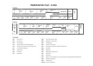
A Description of the <strong>System</strong>1.1 Philosophy behind the <strong>SIMOCODE</strong>-<strong>DP</strong> <strong>3UF5</strong> system<strong>Protection</strong><strong>Control</strong>Current as the centralreference value<strong>SIMOCODE</strong>-<strong>DP</strong> <strong>3UF5</strong> (Siemens <strong>Motor</strong> <strong>Protection</strong> <strong>and</strong> <strong>Control</strong> <strong>Device</strong> -Decentralized Periphery) is a motor protection <strong>and</strong> control device with aPROFIBUS-<strong>DP</strong> interface.The microprocessor is the central element of the system. All motor protection<strong>and</strong> control functions are implemented with the microprocessor, as wellas interlocking functions, the calculation of operating, diagnosis <strong>and</strong> statisticaldata <strong>and</strong> high-performance communication (PROFIBUS-<strong>DP</strong>) between theautomation level <strong>and</strong> the motor branch.The integrated current transformers serve the purpose of detecting themost important measured variable, electric current. Whether for Overload<strong>Protection</strong>, Overload Warning, the current thresholds, the On/Off Check-Back Signal, calculation of the Number of Operating Hours, etc.,<strong>SIMOCODE</strong>-<strong>DP</strong> always takes the electric current as the central referencevalue.Structure The structure of the system is shown in greatly simplified form in Fig. 1:<strong>SIMOCODE</strong>-<strong>DP</strong>PROFIBUS-<strong>DP</strong>DIAGNOSISCONTROLMOTOR PROTECTIONMicroprocessorCurrent detectionFig. 1: Simplified structure of the system1-2 GWA 4NEB 631 4286-02a
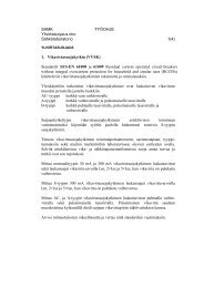
A Description of the <strong>System</strong>What distinguishes the <strong>SIMOCODE</strong>-<strong>DP</strong> system from conventional motorprotection <strong>and</strong> control equipment?Great simplificationLayout usingconventionaltechnology<strong>SIMOCODE</strong>-<strong>DP</strong> <strong>3UF5</strong> greatly simplifies the motor branch. This becomesapparent after examining Fig. 2 "Layout of a motor branch (Direct Starter)using conventional technology" <strong>and</strong> Fig. 3 "Future-oriented circuit diagramwith <strong>SIMOCODE</strong>-<strong>DP</strong>".The figure below shows a layout using conventional technology:3/N/PE ~ 50/60Hz 400/230VL1L2L3NPEQ11 3 51L1-F4-Q1-F2--F3OnOffAutomation level / I/O moduleCheck-Back SignalOverloadThermistor-Q1 openCurrent<strong>Control</strong> comm<strong>and</strong>sMan. / AutoOn / Off2 4 6-X1- K11 3 52 4 6-K11ManualAutoPE- F21 3 52 4 6U VM3~Wϑ 1Local stopS1Local start24 to 20 mAS21N-K1-X2-K1PLCStart/Stop-X3-K12-F3Thermistorevaluation1-K1 -K1 -F2 -F3Switchgear-Q1DA-K11 -K12N2Fig. 2: Layout of a motor branch (Direct Starter) using conventional technologyGWA 4NEB 631 4286-02a 1-3
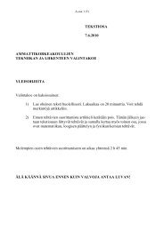
A Description of the <strong>System</strong>Layout with<strong>SIMOCODE</strong>-<strong>DP</strong>Future-orientedcircuit diagramThe <strong>SIMOCODE</strong>-<strong>DP</strong> system alone is used for all control <strong>and</strong> monitoring functions,up to <strong>and</strong> including signal preprocessing. In this way there is no needfor additional overload relays, thermistor evaluation devices, current transformers,analog-to-digital converters etc.. The wiring of the control circuit isdispensed with entirely. The Start <strong>and</strong> Stop switches are wired directly tothe inputs of the <strong>3UF5</strong>0 Basic Unit. The contactor coil is controlled via theoutput of the <strong>3UF5</strong>0 Basic Unit - an auxiliary contact for latching is unnecessary.The "<strong>Motor</strong> On/Off" Check-Back Signal, which in the past was sent viaan auxiliary contact of the contactor, is implemented using the current with<strong>SIMOCODE</strong>-<strong>DP</strong>. This means that when an On comm<strong>and</strong> applies <strong>and</strong> currentis flowing, <strong>SIMOCODE</strong>-<strong>DP</strong> returns the Check-Back Signal "<strong>Motor</strong> On", or inthe event of an Off comm<strong>and</strong> <strong>and</strong> when current is not flowing,<strong>SIMOCODE</strong>-<strong>DP</strong> returns the Check-Back Signal "<strong>Motor</strong> Off".The figure below shows a layout with <strong>SIMOCODE</strong>-<strong>DP</strong>:L1L2L3NPE3/N/PE ~ 50Hz 400/230V1L11NPEPROFIBUS-<strong>DP</strong>2L12NF11Q11 3 5Local <strong>Control</strong> Station2 4 6K11 3 52 4 6S2StartS1StopA1 A2 PE A B61 2 3 4 5Overload protectionCurrent asymmetryPhase failureBlocking protectionCurrent detection<strong>3UF5</strong>0 Basic UnitPE T1 T278 910 11M3~ϑA1-K1A22NRCFig. 3: Future-oriented circuit diagram with <strong>SIMOCODE</strong>-<strong>DP</strong>1-4 GWA 4NEB 631 4286-02a
A Description of the <strong>System</strong>Data transmissionPROFIBUS-<strong>DP</strong>The start/stop signal is transmitted from the automation system (PLC) viathe PROFIBUS-<strong>DP</strong>, as are the Check-Back Signals for on, off, fault overload,fault thermistor, the current etc.All parallel wiring between the automation system <strong>and</strong> the motor branch isomitted. In the example used here, this amounts to 23 clamping points <strong>and</strong>10 cores. Because as many as 122 slaves (<strong>SIMOCODE</strong>-<strong>DP</strong>) can be connectedto the PROFIBUS-<strong>DP</strong> when the system is fully exp<strong>and</strong>ed, the twowirePROFIBUS-<strong>DP</strong> cable replaces 2806 clamping points <strong>and</strong> 1220 cores,<strong>and</strong> therefore also the I/O modules required in the automation system (PLC).Reducing the amountof wiringAs a result of the enormous reduction in the amount of wiring <strong>and</strong> clampingpoints, there are also fewer potential sources of faults.Point-to-point wiringWiring with PROFIBUS-<strong>DP</strong>PLCPROFIBUS-<strong>DP</strong><strong>SIMOCODE</strong>-<strong>DP</strong><strong>Motor</strong> 1 <strong>Motor</strong> 2<strong>Motor</strong> 1 <strong>Motor</strong> 1Fig. 4: Reducing the amount of wiringOmission ofsupplementarycomponentsLogic modulesFast modificationby softwareIf coupling devices <strong>and</strong> terminal boards are used in addition, these can alsobe omitted. Details of how to convert a conventional circuit diagram into afuture-oriented circuit diagram <strong>and</strong> which parameters need to be set areexplained in the chapter on "Configuration".The <strong>SIMOCODE</strong>-<strong>DP</strong> system additionally makes various logic modules available,such as Truth Tables, timers, counters <strong>and</strong> Signal Matching modules.This openness enables you to translate your own installation-specificrequirements into practice with <strong>SIMOCODE</strong>-<strong>DP</strong>.Using the logic modules you can quickly change the functionality via the softwareduring commissioning or during operation. There is no need for complexrewiring.GWA 4NEB 631 4286-02a 1-5
A Description of the <strong>System</strong>AutonomousoperationPROFIBUS-<strong>DP</strong>As all motor protection <strong>and</strong> <strong>Control</strong> Functions are processed according to adecentralized principle in the <strong>SIMOCODE</strong>-<strong>DP</strong> <strong>3UF5</strong> system, the motorbranch can continue to be controlled even in the event of failure of the automationsystem (PLC) or of disturbances on the communication path. Fromthis it also follows that <strong>SIMOCODE</strong>-<strong>DP</strong> can be operated without a connectionto the PROFIBUS-<strong>DP</strong>. The PROFIBUS-<strong>DP</strong> can then be retrofitted as necessary.The non-proprietary PROFIBUS-<strong>DP</strong> (Process Fieldbus - DecentralizedPeriphery), st<strong>and</strong>ardized in DIN (E) 19245 Part 3 EN 50170, establishes thehigh-performance communication link between <strong>SIMOCODE</strong>-<strong>DP</strong> <strong>3UF5</strong>0 <strong>and</strong>the automation system (PLC).<strong>Control</strong> comm<strong>and</strong>s <strong>and</strong> operating, diagnostic <strong>and</strong> statistical data are thereforetransmitted via the two-wire PROFIBUS-<strong>DP</strong> cable.PLC or process control systemUp to 4 bytesCyclical data:• Comm<strong>and</strong> on• Comm<strong>and</strong> off• Manual, automatic• Emergency start• Fault acknowledgement• PLC-CPU monitoringetc.213 bytesAcyclical parameter data:• Set current• CLASS• Current limit values• <strong>Control</strong> functions• Timers• Truth TablesUp to 12 bytesCyclical data:• Check-Back Signal On• Check-Back Signal Off• Warning• Fault• Phase current as %etc.20 bytesDiagnosis:• Overload, thermistor, earth fault, ineach case warning <strong>and</strong>/ortripping• Number of overload trips• Operating hoursetc.<strong>SIMOCODE</strong>-<strong>DP</strong>Fig. 5: Data traffic over the PROFIBUS-<strong>DP</strong> between the PLC <strong>and</strong> <strong>SIMOCODE</strong>-<strong>DP</strong>The communication processor (CP/IM) plugged into the programmable controllertakes care of management of the <strong>SIMOCODE</strong>-<strong>DP</strong> devices connectedto the PROFIBUS-<strong>DP</strong> <strong>and</strong> acts as the interface to the application program.Further processing of the <strong>SIMOCODE</strong>-<strong>DP</strong> data, i.e. integration into thecross-plant control system <strong>and</strong> subsequent data preparation, is performedby the application program.In parallel with this, all <strong>SIMOCODE</strong>-<strong>DP</strong> units can be parameterized, controlled<strong>and</strong> monitored via PROFIBUS-<strong>DP</strong> from a second "central station". Fordetailed information refer to the chapter entitled "Communication <strong>and</strong> DataTransmission".On the following pages you can familiarize yourself with the scope of functions<strong>and</strong> with the available components.1-6 GWA 4NEB 631 4286-02a
A Description of the <strong>System</strong>1.2 OverviewCurrent-dependentmotor protectionThermistor<strong>Motor</strong> <strong>Protection</strong>Earth FaultDetection<strong>Control</strong> FunctionsThe Basic Unit consists of several protective mechanisms for currentdependentmotor protection:• Overload <strong>Protection</strong>• Current Asymmetry• Phase Failure• Blocking <strong>Protection</strong>• Current limit-valuesVersions <strong>3UF5</strong>0.1-A enable Thermistor Detectors to be connected in order tomonitor the motor temperature. You can choose between the followingtypes of detector:• PTC Binary• PTC Analog / KTY• NTC AnalogThe Basic Unit has• an internal Earth Fault Detection component. For motors with three-conductortermination, the unit can determine a possible Earth Fault current from thecurrent balance at a particular time.• an external Earth Fault Detection component for versions <strong>3UF5</strong>0.1-B. Here,the Basic Unit evaluates rated fault currents via an externally connected summation-currenttransformer (3UL22, NSK Catalogue, Part 4).The following parameterizable <strong>Control</strong> Functions are implemented in the system:• Direct Starter• Reversing Starter• Star Delta Starter• Pole Changing Starter• Dahl<strong>and</strong>er Starter• Positioner• Solenoid Valve• Softstarter SIKOSTART 3RW22CommunicationThe system is equipped with the st<strong>and</strong>ard interfaces:• PROFIBUS-<strong>DP</strong>• PROFIBUS-<strong>DP</strong>V1• RS 232 for connecting the PCGWA 4NEB 631 4286-02a 1-7
A Description of the <strong>System</strong>Signal processingin the branchSt<strong>and</strong>ard FunctionBlocksOperatingstatistics <strong>and</strong>diagnostic dataThe system incorporates several supplementary functions which can be setas required:• Signal Matching• Truth Table• Timer• CounterSt<strong>and</strong>ard function blocks are self-contained units, implementing for exampletime-graded restarting of the drives after a mains failure.• Check-Back Signal Test• Operating <strong>Protection</strong> Off• Ready to Start• Undervoltage Off• Graded Restart• External Fault• External Warning• Emergency Start• External Diagnosis• External Check-Back Signal• Test 1 with shutdown• Test 2 without shutdown• Reset• PLC-CPU Fault• <strong>DP</strong> FaultThe <strong>SIMOCODE</strong>-<strong>DP</strong> supplies data such as• <strong>Motor</strong> On / Off / Left / Slow / Close etc.• Fault: Overload / Thermistor / etc.• Warning: Overload / Threshold for upper current exceeded etc.• Operating Current• Operating Hours• Number of switching cycles• Number of Overload Trips• Current for last Overload Trip1-8 GWA 4NEB 631 4286-02a
A Description of the <strong>System</strong>1.3 Components of the <strong>SIMOCODE</strong>-<strong>DP</strong> systemModular system<strong>SIMOCODE</strong>-<strong>DP</strong> is a modular system, the building blocks in the system comprisinga <strong>3UF5</strong>0 Basic Unit, the <strong>3UF5</strong>1 Expansion Module, the <strong>3UF5</strong>2 OperatorPanel, connecting cables <strong>and</strong> the Win-<strong>SIMOCODE</strong>-<strong>DP</strong> <strong>3UF5</strong>7 st<strong>and</strong>ardsoftware for parameterization <strong>and</strong> diagnosis.<strong>3UF5</strong>0 Basic Unit<strong>3UF5</strong>1 Expansion ModuleFig. 6: <strong>SIMOCODE</strong>-<strong>DP</strong> modular system<strong>3UF5</strong>2 Operator Panel<strong>3UF5</strong>7 softwareWin-<strong>SIMOCODE</strong>-<strong>DP</strong><strong>3UF5</strong>7Software for the parameterization, control, diagnosis <strong>and</strong> testing of<strong>SIMOCODE</strong>-<strong>DP</strong>, online via PROFIBUS-<strong>DP</strong> or via the RS232 interface<strong>SIMOCODE</strong>-<strong>DP</strong>. Runs under Windows 95 or Windows NT, switchablebetween German <strong>and</strong> English.Win-<strong>SIMOCODE</strong>-<strong>DP</strong>/Professional <strong>3UF5</strong>710:online via PROFIBUS-<strong>DP</strong> or RS232Win-<strong>SIMOCODE</strong>-<strong>DP</strong>/Smart <strong>3UF5</strong>711:via RS232Fig. 7: Win-<strong>SIMOCODE</strong>-<strong>DP</strong>OM-<strong>SIMOCODE</strong>-<strong>DP</strong>Connecting cables/connectorsBus connection block/bus terminationmoduleStep 7 Object Manager for calling Win-<strong>SIMOCODE</strong>-<strong>DP</strong>/Professional inSIMATIC S7/STEP 7, Version 4.0 or higher.Connection between the Basic Unit, Expansion Module <strong>and</strong>/or OperatorPanel.If the PROFIBUS-<strong>DP</strong> is connected to the 9-pole Sub-D socket of the BasicUnit, st<strong>and</strong>ardized 9-pole Sub-D plugs can be used. Otherwise there is a T-clamp available for connection to terminals A <strong>and</strong> B. The bus terminationmodule with integrated power supply ensures that data traffic is carriedproperly even if the last slave is removed from the bus line(see page1-13).GWA 4NEB 631 4286-02a 1-9
A Description of the <strong>System</strong>1.4 <strong>System</strong> configurations<strong>System</strong> configuration 1: Minimum configurationThe minimum configuration issufficient to enable you to implementall available control functions.Basic Unit (BU)PC / Programming Unit (PU)<strong>System</strong> configuration 2:Basic Unit (BU)Expansion Module (EM)PC / Programming Unit (PU)<strong>System</strong> configuration 3:Operator Panel (OP)Basic Unit (BU)PC / Programming Unit (PU)<strong>System</strong> configuration 4:Operator Panel (OP)Basic Unit (BU)Expansion Module (EM)PC / Programming Unit (PU)Fig. 8: <strong>System</strong> configurations1-10 GWA 4NEB 631 4286-02a
A Description of the <strong>System</strong>1.5 Summary of functionsDiagramBasic Unit<strong>Protection</strong> functionsSummary of functions <strong>SIMOCODE</strong>-<strong>DP</strong> system:Current-dependentmotor protectionCurrent limit valueEarth Fault DetectionThermistor<strong>Motor</strong> <strong>Protection</strong>Blocking <strong>Protection</strong>Branch control<strong>Motor</strong> control 4 Inputs 4 OutputsTest / Status-LEDsSignal processingSignal Matching Truth Table TimerCounterFlickerFlashSt<strong>and</strong>ard Function BlocksCheck-Back Signal Test Operating <strong>Protection</strong> Off Ready to Start Undervoltage OffCST OPO RTS UVOExternal Fault 1 External Fault 2 External Warning Emergency StartExt.Fault1 Ext.Fault2 Ext.Warn.Em.StartExternal Diagnosis Prog. controller CPU Ext. Check-Back Signal 1Ext.Diag PLC-CPU Ext.CS1Ext. Check-Back Signal 2Ext.CS2Ext. Check-Back Signal 3Ext.CS3Test 1 Test 2Reset 1Reset 2Reset 3Communication / Data TransmissionPROFIBUS-<strong>DP</strong> RS 232ExpansionModule8 Inputs 4 outputsOperatorPanel3 <strong>Control</strong> buttons 6 signal LEDs Test / status-LEDsFig. 9: Summary of functionsGWA 4NEB 631 4286-02a 1-11
A Description of the <strong>System</strong>1.6 Structural design of the <strong>SIMOCODE</strong>-<strong>DP</strong> systemFree elementsWhat does free mean?Structural designAs the motor branches differ in terms of protection <strong>and</strong> control functionsfrom one set of switchgear to another, all elements in the <strong>SIMOCODE</strong>-<strong>DP</strong>system are free.Free means that the inputs <strong>and</strong> outputs can be assigned to the various elementssuch as– the <strong>Control</strong> <strong>and</strong> motor protection block,– the Function Blocks,– the Logic Modules etc.This occurs in accordance with the requirements of the installation-specificmotor branch.The figure on page1-13 shows the structural design of the system with itsfree elements in the form of a block diagram:1. The four outputs of the <strong>3UF5</strong>0 Basic Unit.2. The process data (signal bits) that are transmitted from the <strong>SIMOCODE</strong>-<strong>DP</strong> tothe PROFIBUS-<strong>DP</strong> master. There are three different base types.3. The logic modules for Signal Matching, Truth Tables, Timers <strong>and</strong> Counters.4. The <strong>Control</strong> Stations, Auxiliary <strong>Control</strong> inputs, Contactor <strong>Control</strong>s,Function Blocks.5. The four buttons, the three green <strong>and</strong> three yellow LEDsof the <strong>3UF5</strong>2 Operator Panel.6. The four inputs of the <strong>3UF5</strong>0 Basic Unit.7. The process data (control bits) that are transmitted from the PROFIBUS-<strong>DP</strong>master to the <strong>SIMOCODE</strong>-<strong>DP</strong>.8. The eight inputs <strong>and</strong> four outputs of the <strong>3UF5</strong>1 Expansion Module.Plugs <strong>and</strong> sockets You will see that all of the elements have plugs <strong>and</strong> sockets : you canconnect the individual free elements to each other by parameterization.A socket can be used as many times are required, a plug just once.1-12 GWA 4NEB 631 4286-02a
St<strong>and</strong>ard Function BlocksAuxiliary <strong>Control</strong> InputsA Description of the <strong>System</strong>1. 2.3.OutSignal120Matching 1InResetInOut121SignalMatching 2Out122ResetInResetInResetSignalMatching 3OutIn1In2In3In1In2In3In1In2In3In1In2In3In4123SignalMatching 4OutTruthTable 1134OutTruthTable 2135OutTruthTable 3136In5Out1TruthTable 4132InOut2133OutFlashing 1 137OutFlashing 2 138OutFlashing 3 139Out140Flickering 1Out141Flickering 2Out142Flickering 3InInInInInInInInResetInReset144145146147148149150151InInNon-Reset. OutReset Element on126Power Loss 1Non-Reset. OutReset Element on127Power Loss 2Process data PROFIBUS-<strong>DP</strong><strong>SIMOCODE</strong>-<strong>DP</strong> --> <strong>DP</strong>-MasterOutTimer 1 128Basic Type 1, Byte 0...11Basic Type 2, Byte 0...3Basic Type 3, Byte 0...3OutTimer 2 129Out1Out2OutCounter 1 130Out3Out4BU OutputsOutCounter 2 1314.<strong>Control</strong> <strong>and</strong> motor protection blockGroup<strong>Control</strong><strong>Control</strong> StationsLocalQE1229QE2230QE3231<strong>Control</strong> Function<strong>Motor</strong> protection functionsOn1232Off233On2234Operator Enabling<strong>DP</strong>C+MOPPCPOTCTOCSTOPOInformationdata blockRTSUVOExt.Fa1QLE1Ext.Fa2Ext.Warn224225226QLAQLE2QLSOperatingdataEm.StartExt.Diag.PLC-CPU6063Ext.CS1227Overload244Signals(Assignmenttable)Ext.CS2Ext.CS3Test1Test2Thermistor.592762Reset1Reset2Reset330Expansion ModuleOperator PanelGreen1-OPGreen2-OPGreen3-OPYellow1-OPYellow2-OPYellow3-OPButtons T/REM OutputsButtons1Buttons2Buttons3Out1Out2Out3Out489101112131415In1In2In3In4In5In6In7In845675.8.6.Basic Unit <strong>3UF5</strong>0BU InputsLC-On1LC-OffLC-On2In1In2In3In40123<strong>DP</strong>-On1<strong>DP</strong>-Off<strong>DP</strong>-On2565758C+M-On1C+M-OffC+M-On2242526OP-On1OP-OffOP-On2PCS1S261254Process data PROFIBUS-<strong>DP</strong><strong>DP</strong>-Master --> <strong>SIMOCODE</strong>-<strong>DP</strong>Byte 0...3 PROFIBUS-<strong>DP</strong>8072645657 65 73 8158 66 74 8259 67 75 8360 68 76 8461 69 77 8562 70 78 8663 71 79 8732Byte 0...1 <strong>DP</strong>V1247.33343525262736283738EM Inputs29303931Fig. 10: Structural design of the <strong>SIMOCODE</strong>-<strong>DP</strong> systemGWA 4NEB 631 4286-02a 1-13
A Description of the <strong>System</strong>1-14 GWA 4NEB 631 4286-02a
The <strong>3UF5</strong>0 Basic Unit2Section Topic Page2.1 Description 2-22.2 Summary of functions 2-32.3 Outputs 2-42.4 Inputs 2-52.5 <strong>Protection</strong> functions 2-72.5.1 Current-dependent motor protection 2-72.5.2 Current Limit Value / Blocking <strong>Protection</strong> 2-162.5.3 Earth Fault Detection 2-172.5.4 Thermistor <strong>Motor</strong> <strong>Protection</strong> 2-192.6 Branch control 2-212.6.1 <strong>Control</strong> <strong>and</strong> motor protection block 2-212.6.2 Information data block 2-222.6.3 Description of the <strong>Control</strong> Stations 2-232.6.4 Description of the <strong>Control</strong> Functions 2-272.6.5 Description of the Function Block Inputs 2-472.6.6 Test / status LEDs 2-502.7 Logic modules 2-522.7.1 Signal Matching 2-522.7.2 Non-Reseting Elements on Power Loss 2-532.7.3 Truth Table 3I / 1O 2-542.7.4 Truth Table 5I / 2O 2-572.7.5 Flash /Flicker 2-592.7.6 Timers 2-602.7.7 Counters 2-61GWA 4NEB 631 4286-02a 2-1
The <strong>3UF5</strong>0 Basic Unit2.1 DescriptionFrontThe following diagram shows the front of the Basic Unit,e.g. a 230 V version.Connection of a thermistor detector formotor protection or a summation currenttransformer for Earth Fault Detection,depending on the version of the unit.Connection of thesupply voltage• 24 V DC• 115 V AC• 230 V ACA1 A2 T1 T2 1 2 3 4 5AC230VIN1 .2 .3 .44 opto-coupler inputs• 24 V DC,internally supplied• External 24 V DCpossible3 LED displaysUnit test, manual reset• Automatic reset parameterizable• Remote reset via bus orinput4 Output RelaysReadyBusGen.Fault6,3...25ATest/ResetPROFIBUS-<strong>DP</strong>G/9542 <strong>3UF5</strong>011-3AN00-1OUT 16 7.2.3.4 PROFIBUS-<strong>DP</strong>Sys.<strong>3UF5</strong>8 9 10 11 B A SPE/E<strong>System</strong> interfaceincl. RS 232• For connection ofExpansion Module,Operator Panel <strong>and</strong> PCBus terminal forPROFIBUS-<strong>DP</strong>• 9-pole SUB-D socket• Terminal, provided forplug-in unitsFig. 11: Front of Basic Unit2-2 GWA 4NEB 631 4286-02a
The <strong>3UF5</strong>0 Basic Unit2.2 Summary of functionsDiagramBasic Unit<strong>Protection</strong> functionsThe following diagram contains a summary of the functions performed bythe <strong>3UF5</strong>0 Basic Unit:Current-dependentmotor protectionCurrent limit valueEarth Fault DetectionThermistor<strong>Motor</strong> <strong>Protection</strong>Blocking <strong>Protection</strong>Branch control<strong>Motor</strong> control 4 Inputs 4 OutputsTest / Status-LEDsSignal processingSignal Matching Truth Table TimerCounterFlickerFlashSt<strong>and</strong>ard Function BlocksCheck-Back Signal Test Operating <strong>Protection</strong> Off Ready to Start Undervoltage OffCST OPO RTS UVOExternal Fault 1 External Fault 2 External Warning Emergency StartExt.Fault1 Ext.Fault2 Ext.Warn.Em.StartExternal Diagnosis Prog. controller CPU Ext. Check-Back Signal 1Ext.Diag PLC-CPU Ext.CS1Ext. Check-Back Signal 2Ext.CS2Ext. Check-Back Signal 3Ext.CS3Test 1 Test 2Reset 1Reset 2Reset 3Communication / Data TransmissionPROFIBUS-<strong>DP</strong> RS 232Fig. 12: Summary of functions performed by the Basic UnitGWA 4NEB 631 4286-02a 2-3
The <strong>3UF5</strong>0 Basic Unit2.3 OutputsDescription of functionsThe Basic Unit has 4 Output Relays with which, for example, you can operatecontactors or lamps.BistablebehaviourDiagramIf the status of the Output Relays is to be retained when the supply voltageis cut off, you have to select the 3UF..-3.10-1 version of the unit (bistablebehaviour).Then, you have to set the parameters for• "Response - <strong>3UF5</strong>0 CPU Fault" <strong>and</strong>• "Response - <strong>Control</strong> Voltage Fault"to "Retain Status".The following diagram shows the Output Relays.InternalinputsOut1Out2Out3Out4Circuit OutputBU Outputsterminal No.67891011Fig. 13: Diagram of Output Relays for Basic Unit2-4 GWA 4NEB 631 4286-02a
The <strong>3UF5</strong>0 Basic Unit2.4 InputsDescription of functionsThe Basic Unit has 4 inputs with which you can interrogate mechanical contactsor detectors.ExamplesIf you wish, you can wire up the START <strong>and</strong> STOP keys of the Local <strong>Control</strong>to the inputs, <strong>and</strong> assign the internal control to "local".With the signals, you can, for example, activate Function Blocks such as"Reset" or "Ready to Start (RTS)" by appropriate assignment of the inputs.SchemaInputterminal No 1234BU InputsIn1In2In3In4InternalOutputs0123Fig. 14: Diagram of the Inputs for Basic UnitInput delayFor reasons of interference immunity, you can set a debounce time for theinputs.GWA 4NEB 631 4286-02a 2-5
The <strong>3UF5</strong>0 Basic UnitVoltage supply• internal 24 V DC supply, if you are using mechanical contacts• external 24 V DC supply, if you are using solid-state sensors (e.g. limit switchesfor level measurements). Input 1 is the reference potential, i.e. threeinputs are available to you.• external 24 V DC, if you are using mechanical contacts. A2 is the referencepotential, i.e. there are four inputs available (only 24 V DC versions of theunit).In1 .2 .3 .41 2 3 4 5Possible input circuitryfor all AC / DC versions of the unitInput circuitry with internal24 V DC (pulsed)Buffering 20 ms+_In1 .2 .3 .41 2 3 4Input circuitry with external24 V DC.+_A1A2In1 .2 .3 .41 2 3 4Possible input circuitryfor 24 V DC versionsInput circuitry with external24 V DC (pulsed)All four inputs can therefore beused.Fig. 15: Diagram of input circuitryNoteThe internal 24 V DC voltage supply must be used for the inputs of the BasicUnit only.Cable lengthsFurther information about cable lengths is given in the appendix,page C-5.2-6 GWA 4NEB 631 4286-02a
The <strong>3UF5</strong>0 Basic UnitCurrent detectionbelow 1.25 AYou can also detect motor currents of less than 1.25 A with <strong>SIMOCODE</strong>-<strong>DP</strong>.To do this you must run the motor supply leads through the push-throughopenings <strong>and</strong> form an appropriate number of loops. This has the effect ofamplifying the primary signal.Proceed as follows:1. Insert the motor supply leads phase by phase through thepush-through openings X2. Guide them back through the loop-through opening Y3. Push them through the push-through openings X again. This gives you twoloops.YXFig. 17: Push-through <strong>and</strong> loop-through openings on the <strong>3UF5</strong>001 Basic UnitThe table below shows the number of loops for the corresponding levels ofmotor rated current.Number of loops n 5 4 3 2<strong>Motor</strong> rated current I N [A] 0.25 to 0.31 to 0.42 to 0.63 to0.3 0.41 0.62 1.24Current to be set Is [A]Table 2: Detection of motor currents below 1.25 A1.25 to1.51.25 to1.641.26 to1.821.26 to2.48The Set Current for the unit I s is calculated thus: I s = n x I NExample I N = 0.5 A; n = 3;Current to be set: I s = 1.5 AGWA 4NEB 631 4286-02a 2-9
The <strong>3UF5</strong>0 Basic UnitTripping classes, specified times, thermal memoryClassThe class (tripping class) indicates the maximum tripping time in which aprotection device has to trip from cold at 7.2 times the Set Current (motorprotection according to IEC 60947). The tripping characteristics show thetripping time in relation to the tripping current.1201005012010050Deratings min201052150201051510CLASS 52x I s10,7 1 2 5 83-pole symmetrical loadt ACLASS 302520Fig. 19: Tripping characteristics (cold)s min1015510CLASS 52x I s10,7 1 2 5 82-pole load(failure of a phase or currentasymmetry > 40 %)Bear in mind that, for starts > Class 10, the permissible AC3 current of themotor contactor has to be reduced (derating). The data (rated operatingcurrents Is [A] /AC-3) are given in Appendix D.5.20105215020t ACLASS 302520GWA 4NEB 631 4286-02a 2-11
The <strong>3UF5</strong>0 Basic UnitWarm tripping"thermal memory"When the motor is warm, the tripping times are reduced by the factors listedin the table. These factors apply to 3-pole symmetrical loads, Class 5 toClass 30:x I sPre-loading in % of the Set Current I s0 20 40 60 80 1001.15 1 1 1 1 1 12 1 0.88 0.74 0.58 0.40 0.194 1 0.85 0.69 0.52 0.35 0.168 1 0.84 0.67 0.51 0.33 0.15Table 3: Factors for tripping times when the motor is warmExampleFailure ofsupply voltageYou have operated the motor with a Set Current of 100 % I s <strong>and</strong> turned it off.You turn the motor on again immediately. Tripping due to overload with 2 xI s , Class 10, occurs.Tripping time when cold: approx. 40 s (tripping characteristic).Factor for tripping time in the event of pre-loading 100 % I s : 0.19 (table).Reduced tripping time: 0.19 x 40 s = 7.6 sIf the supply voltage to the <strong>3UF5</strong>0 Basic Unit fails for longer than 200 ms,the thermal memory is lost. In the event of an overload, the remaining coolingtime is stored.2-12 GWA 4NEB 631 4286-02a
The <strong>3UF5</strong>0 Basic UnitType of protectionEEX eExampleThe <strong>SIMOCODE</strong>-<strong>DP</strong> <strong>3UF5</strong> system conforms to the regulations for the overloadprotection of explosion-protected motors of the "increased safety" typeof protection EEx e DIN EN 50 0019 / DIN VDE 0165, DIN VDE 0170/0171 <strong>and</strong>to the PTB test regulations.In the case of tripping units with DC operation, electrical isolation must beensured by a battery or safety isolating transformer conforming toDIN VDE 0551.Separate monitoring of the control supply voltage is recommended if the<strong>SIMOCODE</strong>-<strong>DP</strong> <strong>3UF5</strong> system is used with parameterized bistable behaviourof the output relays (Order No. <strong>3UF5</strong>0..-3..10-1) for the protection of motorswith increased safety.PTB test report no. 3.53-14605/96.<strong>Protection</strong> of motors in potentially explosive atmospherest E12010050201052150201051510CLASS 5CLASS 302520Example:<strong>Motor</strong> 400 V, 50/60 Hz, 1.5 kW, 3.3 At E time where T3 = 21 sI A / I N = 6.5Critical firing point,selected: Class 102t A10,7x I e1 2 5 8I A / I NFig. 20: <strong>Protection</strong> of motors in potentially explosive atmospheresOriginal trippingcharacteristicsYou can request the original tripping characteristics (precision ± 10 %), especiallyfor EEexe applications, fromSiemens AGA&D CD SV TGP 2Tel.: ++49-9621-80-2127Fax: ++49-9621-80-3141GWA 4NEB 631 4286-02a 2-13
The <strong>3UF5</strong>0 Basic UnitCooling TimeEmergencyStartIdle TimeThe Cooling Time is the specified time after which the unit can be reset followingtripping due to overload.Voltage failures during this time lengthen the specified time accordingly.The Cooling Time after Overload Trip is at least 5 minutes. You can set theCooling Time <strong>and</strong>, if necessary, extend it.A way of deleting the thermal memory <strong>and</strong> bypassing the Cooling Time, thusallowing a restart. (Reset <strong>and</strong> Switch-On comm<strong>and</strong>s also necessary!). TheEmergency Start is only activated by edges. A new overload trip can neverbe prevented.The Idle Time is the time specified for cooling when the motor at operatingtemperature is turned off by <strong>Control</strong> Functions (not due to overload!).After this time, the thermal memory is deleted <strong>and</strong> a cold start is possible.This allows frequent starting.The following diagram shows cooling behaviour with <strong>and</strong> without Idle Time:<strong>Motor</strong>OnOfftWithout Idle TimeυTripping limitOverload TriptυWith Idle TimeTripping limitNo Overload TriptIdle Time.Thermal memory deleted after the Idle TimeFig. 21: Cooling behaviour with <strong>and</strong> without Idle Time2-14 GWA 4NEB 631 4286-02a
The <strong>3UF5</strong>0 Basic UnitSettingsThe following table contains a description of the settings.Designation Range CommentsSet Current Is1 1.25 A to 820 A Set Current 1.Range depends onversion*Set Current Is2 1.25 A to 820 A Set Current 2. Rangedepends on version.Only for "Fast" operatingmode when Dahl<strong>and</strong>er /Pole Changing Starter isused, otherwise 0.Tripping class / Class 5, 10, 15, 20, 25, 30Behaviour in the eventof overloadShutdownWarningCooling Time 0.5 s to 60 min At least 5 min.,even when lower valuesare set. Example:Cooling Time:6 min required; time tobe set: 6 minIdle TimeSingle-phase motor0.5 s to 60 minNoYesOnly one conductingpath may be connectedthrough/to the first currenttransformer. InternalEarth FaultDetection has to bedeactivated.Table 4: Description of the settings for current-dependent motor protectionThe parameters are summarized in the parameter table (Appendix A.2).* With Star Delta Starter:I s 1 = I n------1 3Example: motor with I n =100 A. I s 1 = 57.7 A.GWA 4NEB 631 4286-02a 2-15
The <strong>3UF5</strong>0 Basic Unit2.5.2 Current Limit Value / Blocking <strong>Protection</strong>Descriptions of functionsYou can enter a lower <strong>and</strong>/or an upper Current Limit.Example:"Stirring mass too thick", i.e. the upper Current Limit has been exceeded."Idling as drive belt torn", i.e. the level has fallen below the lower limit.The Current Limit Values <strong>and</strong> the Blocking <strong>Protection</strong> function are - for startbypassing purposes - only active after the class time has expired, z.B. Class10 nach 10 Sekunden. If a current limit is exceeded or if the current fallsbelow a limit, the <strong>SIMOCODE</strong>-<strong>DP</strong> reacts• by turning off the Contactor <strong>Control</strong>s QE1 / QE2 / QE3 or• with a warning,depending on the setting you have entered.The Blocking <strong>Protection</strong> function always turns off the Contactor <strong>Control</strong>sQE1 / QE2 / QE3 instantaneously.SettingsThe following table contains a description of the settings:Designation Range CommentsResponse threshold forlower Current LimitBehaviour if the currentfalls below the lowerCurrent LimitResponse threshold forupper Current LimitBehaviour if the upperCurrent Limit isexceeded20% to 1000%of the Set CurrentWarningShutdown20% to 1000%of the Set CurrentWarningShutdownin steps of 5%in steps of 5%Blocking 20% to 1000%of the Set CurrentIn steps of 5%Always shutdownTable 5: Description of the settings for Current Limit Values / Blocking <strong>Protection</strong>The parameters are summarized in the parameter table (Appendix A.2).2-16 GWA 4NEB 631 4286-02a
The <strong>3UF5</strong>0 Basic Unit2.5.3 Earth Fault DetectionDescription of functionInternalfunctionNoteThe internal Earth Fault Detection function is only suitable for motors with a3-conductor connection <strong>and</strong> for earthed power systems! You can activatethe internal Earth Fault Detection function by means of parameterization. Itcovers two sets of circumstances during operation:• normal operation at up to 2 x I s . The operating current has to be less than doublethe Set Current I s . Fault currents amounting to > 30 % of the Set CurrentI s are detected.• starting or overload at above 2 x I s . The operating current is greater than doublethe Set Current I s . Fault currents amounting to > 15 % of the motor currentare detected.If you are using internal Earth Fault Detection with a Star Delta Starter connection,spurious tripping may occur. In delta operation the net current is notequal to zero because of harmonic waves.ExternalfunctionYou can operate internal Earth Fault Detection in parallel with Thermistor<strong>Motor</strong> <strong>Protection</strong>.With the 3UL22 summation current transformer, rated fault currents of 0.3A, 0.5 A <strong>and</strong> 1 A are evaluated. Response delay time: > 200 ms.If the earth-fault limit is exceeded, a signal is emitted. You can specify additionaltripping circumstances by means of parameterization.NoteThe external Earth Fault Detection function is an alternative to Thermistor<strong>Motor</strong> <strong>Protection</strong> (version of unit).If the rated fault currents are exceeded,<strong>SIMOCODE</strong>-<strong>DP</strong> responds either• with shutdown of the Contactor <strong>Control</strong>s QE1 / QE2 / QE3 or• with a warningdepending on what you have set.GWA 4NEB 631 4286-02a 2-17
The <strong>3UF5</strong>0 Basic UnitDiagramThe following diagram shows an example of Earth Fault Detection:L1L2L3NOnly unit versions <strong>3UF5</strong>0.1-3B...-1External3UL22C1C2A1A2SPE/PE6101235InternalOVERLOADCURRENT ASYMMETRYPHASE FAILUREBLOCKING PROTECTIONCURRENT DETECTION<strong>3UF5</strong>0 Basic Unit789114M3~Fig. 22: Diagram of Earth Fault DetectionSettingsThe following table contains a description of the settings:Designation Range CommentsInternalEarth Fault DetectionExternalEarth Fault DetectionBehaviour in the eventof an earth-faultYesNoYesNoWarningShutdownActiveNot activeActiveNot activeTable 6: Description of the settings for Earth Fault DetectionThe parameters are summarized in the parameter table (Appendix A.2).2-18 GWA 4NEB 631 4286-02a
The <strong>3UF5</strong>0 Basic Unit2.5.4 Thermistor <strong>Motor</strong> <strong>Protection</strong>Description of functionsOperationA Thermistor-detector circuit can be connected to versions <strong>3UF5</strong>0.1 to 3A...for direct temperature detection. Thermistor <strong>Motor</strong> <strong>Protection</strong> is an alternativeto external Earth Fault Detection.If the resistance values are exceeded (PTC) or fall below a certain value(NTC), the <strong>SIMOCODE</strong>-<strong>DP</strong> reacts either• by turning off the Contactor <strong>Control</strong>s QE1 / QE2 / QE3 or• with a warning,depending on the setting you have entered.NoteThermistor <strong>Motor</strong> <strong>Protection</strong> is an alternative to the external Earth FaultDetection function (version of unit).Types of detectorThree types of detector can be evaluated:Type Behaviour Characteristic Comments1 PTCBinaryRWarning or shutdown can be set.2 PTCAnalogKTY3 NTCAnalog1 2 υTable 7: Types of detector for Thermistor <strong>Motor</strong> <strong>Protection</strong>RR1 2υυTwo thresholds can be evaluated.1. Warning <strong>and</strong>2. ShutdownTwo thresholds can be evaluated.1. Warning <strong>and</strong>2. ShutdownGWA 4NEB 631 4286-02a 2-19
The <strong>3UF5</strong>0 Basic UnitDiagramThe following diagram shows an example of Thermistor <strong>Motor</strong> <strong>Protection</strong>:L1L2L3NOnly device versions <strong>3UF5</strong>0.1-3A..T1T2A1A2SPE/PE1235OVERLOADCURRENT AYMMETRYPHASE FAILUREBLOCKING PROTECTIONCURRENT DETECTION<strong>3UF5</strong>0 Basic Unit789116104M3~ϑFig. 23: Diagram for Thermistor <strong>Motor</strong> <strong>Protection</strong>SettingsThe following table contains a description of the settings.Designation Range CommentsPTC BinaryBehaviour PTC BinaryPTC Analog/KTYNTC AnalogYesNoWarningShutdownYesNoYesNoActiveNot activeActiveNot activeActiveNot activeAnalog trippingthresholdAnalog warningthreshold0..5,1 km Increment 20 m0...5,1 km Increment 20 mShort-circuit in detectorlineYes / NoOnly indicatedTable 8: Description of the settings for Thermistor <strong>Motor</strong> <strong>Protection</strong>The parameters are summarized in the parameter table (Appendix A.2.).2-20 GWA 4NEB 631 4286-02a
Function Block InputsAuxiliary control inputsThe <strong>3UF5</strong>0 Basic Unit2.6 Branch control2.6.1 <strong>Control</strong> <strong>and</strong> motor protection blockDescription of functionsIn order to provide reliable protection of the motor branch, you must assignthe control comm<strong>and</strong>s to the control <strong>and</strong> motor protection block.NoteOtherwise Operator Enabling signals, <strong>Control</strong> Functions <strong>and</strong> protection functionshave no effect.DiagramThe principle is illustrated in the following diagram:<strong>Control</strong> <strong>and</strong> motor protection blockLOC-On1LOC-OffLOC-On2<strong>DP</strong>-On1<strong>DP</strong>-Off<strong>DP</strong>-On2C+M-On1C+M-OffC+M-On2<strong>Control</strong> StationsLocal<strong>DP</strong>C+MOperator EnablingGroupcontrolStationOn1232Off233On2234<strong>Control</strong> Function<strong>Motor</strong> protection functionsQE1QE2QE3229230231OP-On1OP-OffOP-On2OPPCS1S2CSTOPORTSUVOExt.Fa1Ext.Fa2Ext.WarnEm.StartExt.Diag.PLC-CPUExt.CS1Ext.CS2Ext.CS3Test1Test2Reset1Reset2Reset3PCPOTCTOFig. 24: <strong>Control</strong> <strong>and</strong> motor protection blockGWA 4NEB 631 4286-02a 2-21
The <strong>3UF5</strong>0 Basic Unit<strong>Control</strong> Stations<strong>Control</strong> Function<strong>Motor</strong> protectionfunctionThe set Operator Enabling signals are processed in the <strong>Control</strong> Stationsblock, <strong>and</strong> the <strong>Control</strong> Function, for example reversing starter, in the nextblock. Depending on which <strong>Control</strong> Function is selected, all interlocks, logicoperations <strong>and</strong> delays are implemented here. If Function Blocks are requiredor Auxiliary <strong>Control</strong> Inputs need to be used, for example for actuator/Positionercontrol, these have an effect on the <strong>Control</strong> Function.The motor protection function acts as the last block in this chain. The Contactor<strong>Control</strong>s QE1/QE2/QE3 switch in accordance with the <strong>Control</strong> Functionbeing used, see Table 11: on page 2-27.The Contactor <strong>Control</strong>s QE1/QE2/QE3 have a high signal after an "On" comm<strong>and</strong><strong>and</strong> a low signal after an "Off" comm<strong>and</strong> or if a fault applies, in otherwords the motor branch is reliably switched on <strong>and</strong> off even in the event of afault.Reliable on/offswitchingThe Contactor <strong>Control</strong>s QE1/QE2/QE3 reliably switch the motor branch on<strong>and</strong> off.2.6.2 Information data blockDescription of functionsThe information data block makes important operating data <strong>and</strong> signals available,such as On, Off, Left, Right, Slow, Fast, Close, Open, warnings, faultsetc. (see also assignment table, Appendix A.1). You can connect these signalsto the outputs of the system, transmit them via PROFIBUS-<strong>DP</strong> or displaythem on the Operator Panel.DiagramThe principle is shown in the following diagram:Informationdata blockQLE1QLAOperating dataQLE2QLS224225226227244signals(assignmenttable A.1)Overload.ThermistorFig. 25: Diagram of information data block2-22 GWA 4NEB 631 4286-02a
The <strong>3UF5</strong>0 Basic Unit2.6.3 Description of the <strong>Control</strong> Stations<strong>Control</strong> Stations are points from where switching comm<strong>and</strong>s (for example<strong>Motor</strong> On or <strong>Motor</strong> Off) are issued. Possible <strong>Control</strong> Stations include:1. Local <strong>Control</strong> Station, which is situated in the immediate vicinity of the motor<strong>and</strong> is operated via pushbuttons, for example.2. PROFIBUS-<strong>DP</strong>, switching comm<strong>and</strong>s from the automation system (PLC).3. HMI, as an additional option for control via an operator control <strong>and</strong> monitoringstation (human-machine interface)or via PROFIBUS-<strong>DP</strong>V1 with theWin-<strong>SIMOCODE</strong>-<strong>DP</strong>/Professional software.4. <strong>3UF5</strong>2 Operator Panel, which is fitted in the switchgear cubicle door.The <strong>SIMOCODE</strong>-<strong>DP</strong> system provides these <strong>Control</strong> Stations internally. The<strong>Control</strong> Stations each have three internal inputs: On1, On2, Off.NoteThe internal input LOC-Off is inverted <strong>and</strong> 0 is therefore active. As a resultthe Contactor <strong>Control</strong>s QE1/QE2/QE3 are deactivated in the event of a wirebreak in the supply lead to the external stop button, for example, <strong>and</strong> canonly be reactivated when the fault has been rectified.LOC-On1LOC-OffLOC-On2<strong>DP</strong>-On1<strong>DP</strong>-Off<strong>DP</strong>-On2C+M-On1C+M-OffC+M-On2OP-On1OP-OffOP-On2<strong>Control</strong> StationsLocal<strong>DP</strong>C+MOPOperator EnablingThe options for assignment to the internalinputs of the <strong>Control</strong> Stations include, forexample:• the external Local <strong>Control</strong> Station (start <strong>and</strong>stop buttons, which are wired to the inputsof the <strong>3UF5</strong>0 Basic Unit)• the buttons of the Operator Panel• the PROFIBUS-<strong>DP</strong> control bits• the PROFIBUS-<strong>DP</strong>V1 control bitsS1S2PCFig. 26: Diagram of <strong>Control</strong> StationsGWA 4NEB 631 4286-02a 2-23
The <strong>3UF5</strong>0 Basic UnitOperator EnablingOperator Enabling signals are switching authorizations for various <strong>Control</strong>Stations. The table shows the four possible <strong>Control</strong> Stations which you canenable with operating mode <strong>Control</strong> Mode Switches S1 <strong>and</strong> S2..OperatingmodeChangeoverswitchesS1 S2 Local <strong>Control</strong> Station[LOC]<strong>Control</strong> StationPLC [<strong>DP</strong>] Operator’s station [HMI] Switchgear cubicle,Operator Panel [OP]Signal On Off On Off On Off On Off1 0 0 Free Free Blocked Blocked Blocked Blocked Blocked Blocked2 0 1 Free Free Blocked Blocked Blocked Blocked Blocked Blocked3 1 0 Blocked Blocked Blocked Blocked Free Free Blocked Blocked4 1 1 Blocked Blocked Free Free Blocked Blocked Blocked BlockedTable 9: Operating modes of <strong>Control</strong> StationsYou can set all grey-shaded "Blocked" fields to either "Free" or "Blocked".If you do not change the assignment of S1 <strong>and</strong> S2, <strong>SIMOCODE</strong>-<strong>DP</strong> automaticallysets operating mode 2. You can switch between operating modes 2, 3<strong>and</strong> 4 by activating or deactivating S1 <strong>and</strong> S2.If you also want it to be possible to switch off from the local <strong>Control</strong> Stationin operating mode 4, for example, "Free" must be set for the Off comm<strong>and</strong> inoperating mode 4, "Local" column.Automatic modeA high signal must be present at <strong>Control</strong> Mode Switches S1 <strong>and</strong> S2 for automaticmode (operating mode 4). <strong>SIMOCODE</strong>-<strong>DP</strong> can then be controlled bythe automation system via the PROFIBUS-<strong>DP</strong>. The particular feature of automaticmode is that, in the event of failure of the CPU of the automation system(PLC) or failure of the communication link (PROFIBUS-<strong>DP</strong>),<strong>SIMOCODE</strong>-<strong>DP</strong> can switch to the other operating mode:• automatically, manual/automatic changeover (<strong>Control</strong> Mode Switches S1 <strong>and</strong>S2) with the automation system• by h<strong>and</strong>, manual/automatic changeover (<strong>Control</strong> Mode Switches S1 <strong>and</strong> S2)locally, for example with a key-operated switchDepending on which behaviour is set, <strong>SIMOCODE</strong>-<strong>DP</strong> deactivates the motorbranch or maintains the status.2-24 GWA 4NEB 631 4286-02a
The <strong>3UF5</strong>0 Basic UnitExample 1Local - AutomaticIn practice usually only one changeover function is used, for example inorder to change over the switching authorization between the local <strong>Control</strong>Station <strong>and</strong> the automation system (PLC) with a key-operated switch or acomm<strong>and</strong> from the automation system.Example 1: Local - Automatic. You want to use a PROFIBUS-<strong>DP</strong> control bit toswitch between the local <strong>Control</strong> Station/operating mode 2 (local) <strong>and</strong> controlvia PROFIBUS-<strong>DP</strong>/operating mode 4 (automatic mode).To do this, PROFIBUS-<strong>DP</strong> control bit 0.5 to S1 <strong>and</strong> S2 must be assigned tothe "fixed level value 1".If you want to switch over using a key-operated switch, you must connectthe contact of the key-operated switch to an input terminal of the Basic Unit<strong>and</strong> assign the input terminal to <strong>Control</strong> Mode Switch S1.Example 2Local - Remote -AutomaticIn complex installations it may be necessary to have two changeover functions,S1 <strong>and</strong> S2, for example in order to change the switching authorizationfrom different locations with two key-operated switches.Example 2: Local - Remote - AutomaticYou want to use a PROFIBUS-<strong>DP</strong> control bit to switch between the local<strong>Control</strong> Station/operating mode 2 (local) <strong>and</strong> control via PROFIBUS-<strong>DP</strong>/operatingmode 4 (automatic) <strong>and</strong> in addition you want to enable the <strong>3UF5</strong>2Operator Panel on the switchgear cubicle/operating mode 2 (remote) withequal authorization along with the local <strong>Control</strong> Station.To do this, PROFIBUS-<strong>DP</strong> control bit 0.5 to S1 <strong>and</strong> S2 must be assigned tothe "fixed level value 1".If you want to switch over using a key-operated switch, you must connectthe contact of the key-operated switch to an input terminal of the Basic Unit<strong>and</strong> assign the input terminal to software <strong>Control</strong> Mode Switch S1.In addition you must set "Free" for the On <strong>and</strong> Off comm<strong>and</strong>s in operatingmode 2, "Switchgear cubicle" column.GWA 4NEB 631 4286-02a 2-25
The <strong>3UF5</strong>0 Basic UnitSetting withCOM-PROFIBUS/Step 7If you set <strong>and</strong> assign the parameters via COM-PROFIBUS or Step 7, youshould determine the Operator Enabling signals from the following table:Operatingmode<strong>Control</strong>ModeSwitch<strong>Control</strong> StationLocal <strong>DP</strong> Reserve OPS1 S2 On1/2OffOn1/2OffOn1/2OffOn1/2Off1 0 0 Free Blocked2 0 1 Free Blocked OE4 OE12OE6OE143 1 0 OE2 OE10Blocked Free OE7 OE154 1 1 OE1 OE9 Free OE3 OE11Table 10: Determining Operator Enabling signalsOE5OE13In order to grant Operator Enabling to the Operator Panel in operating mode2 as in Example 2, OE6 <strong>and</strong> OE14 must be set to "1" at the correspondingpoint in the bit pattern.Example:In COM-PROFIBUS or Step 7 the following bit pattern must be set in the<strong>Motor</strong> menu group:• <strong>Motor</strong> " OE 15 14 13 12 11 10 9Entry "0100000", i.e. OE 14 enabled• <strong>Motor</strong> " OE 7 6 5 4 3 2 1Entry "0100000", i.e. OE 6 enabled2-26 GWA 4NEB 631 4286-02a
The <strong>3UF5</strong>0 Basic Unit2.6.4 Description of the <strong>Control</strong> FunctionsThe <strong>Control</strong> Functions of the <strong>SIMOCODE</strong>-<strong>DP</strong> system implement all interlocks,logic operations <strong>and</strong> delays.If Auxiliary <strong>Control</strong> Inputs are required, as for Actuator/Positioner control forexample, or functions blocks need to be used, these have an influence (asdescribed) on the <strong>Control</strong> Function.Normal operationInching ModeExamplesIn normal operation, without Inching Mode being activated, the switchingcomm<strong>and</strong> to the respective input of the "ON1/ON2" <strong>Control</strong> Station is stored<strong>and</strong> can only be cancelled by a switching comm<strong>and</strong> to the respective inputof the "OFF" <strong>Control</strong> Station. This means that the auxiliary contact for lockingthe contactor is not necessary when using <strong>SIMOCODE</strong>-<strong>DP</strong>.The "Inching Mode" function acts on the inputs of all "ON1" <strong>and</strong> "ON2" <strong>Control</strong>Stations. If Inching Mode is activated, a switching comm<strong>and</strong> only has aneffect provided a "high" signal is present.In the Typical Circuits section you will find an example for each <strong>Control</strong> Functionin the form of a circuit diagram, block diagram <strong>and</strong> parameter list.General comments on the Direct Starter, Reversing Starter, Star DeltaStarter, Dahl<strong>and</strong>er Starter, Pole Changing Starter <strong>and</strong> Soft StarterClosingDepending on which <strong>Control</strong> Function is used, after an "On" comm<strong>and</strong> to the"ON1/ON2" <strong>Control</strong> Station the respective Contactor <strong>Control</strong>s QE1/QE2/QE3are activated:<strong>Control</strong>function<strong>Control</strong> Station Contactor <strong>Control</strong> Lamp <strong>Control</strong>Check-Back SignalStatus messageON1 ON2 OFF QE1 QE2 QE3 QLE1(On1)QLE2(On2)QLA(Off)On1 On2 OffDirect Starter(DIR)Reversingstarter(REV)- On Off On - - - On Off - On OffLeft Right Off Left Right - Left Right Off Left Right OffStar Delta Starter(STAR)- On Off MainscontactorStarcontactorDeltacontactor- On Off - On OffPole ChangingStarter(PREV)Slow Fast Off Slow Fast - Slow Fast Off Slow Fast OffDahl<strong>and</strong>er(DAHL)Slow Fast Off Fast Slow Fast starcontacrorSlow Fast Off Slow Fast OffSoft Starter(SOFT)- On Off On comm<strong>and</strong>SIKO-STARTOn -mainscontactor(dropoutdelay)Reset -SIKO-START- On Off - On OffTable 11: Active <strong>Control</strong> Stations, Contactor <strong>Control</strong>s, Lamp <strong>Control</strong>s <strong>and</strong> status messages with Direct Starter, Reversing Starter, Star DeltaStarter, Dahl<strong>and</strong>er starter, Pole Changing Starter <strong>and</strong> Soft StarterGWA 4NEB 631 4286-02a 2-27
The <strong>3UF5</strong>0 Basic UnitCheck-Back CurrentOnOpeningCheck-Back CurrentOffFaultCurrent measurementRun Time On(T-Run Time)Run Time Off(T-Run Time)The <strong>SIMOCODE</strong>-<strong>DP</strong> system determines the Check-Back Signal "<strong>Motor</strong> running"or "Contactor has picked up" by measuring the current in the main circuit:"Current flowing" signifies that the motor is switched on. There is no needfor an auxiliary contact on the contactor for signalling purposes. The "On"state is signalled by the Lamp <strong>Control</strong>s QLE1/QLE2 or by "status messageOn1/On2" (Table 11: on page 2-27).Depending on which <strong>Control</strong> Function is used, after an "Off" comm<strong>and</strong> to the"OFF" <strong>Control</strong> Station the respective Contactor <strong>Control</strong>s QE1/QE2/QE3 asshown in Table 11: on page 2-27 are deactivated.The <strong>SIMOCODE</strong>-<strong>DP</strong> system determines the Check-Back Signal "<strong>Motor</strong> Off"or "Contactor has dropped out" by measuring the current in the main circuit:"No current flowing" signifies that the motor is switched off. There is noneed for an auxiliary contact on the contactor for signalling purposes. The"Off" state is signalled by the Lamp <strong>Control</strong> QLA or by "status message Off"(Table 11: on page 2-27).The Contactor <strong>Control</strong>s QE1/QE2/QE3 are deactivated. In addition, a flashsignal is applied to the Lamp <strong>Control</strong> QLS, <strong>and</strong> the Gen. Fault flash signal,the "General Fault" status message <strong>and</strong> the corresponding signal bit for thefault are present.The current in the main circuit is measured using the integrated currenttransformers in the <strong>3UF5</strong>0 Basic Unit.After an "On" comm<strong>and</strong>, <strong>SIMOCODE</strong>-<strong>DP</strong> must measure the current in themain circuit during Run Time. If it does not, the fault message "Run Time On"is issued <strong>and</strong> <strong>SIMOCODE</strong>-<strong>DP</strong> deactivates the Contactor <strong>Control</strong>s QE1/QE2/QE3.After an "Off" comm<strong>and</strong>, <strong>SIMOCODE</strong>-<strong>DP</strong> is not permitted to measure anycurrent in the main circuit after the Run Time. Otherwise the fault message"Run Time Off" is issued <strong>and</strong> the Contactor <strong>Control</strong>s QE1/QE2/QE3 cannotbe switched back in until after the fault has been rectified.• We recommend not changing the factory setting.• The Run Time can be deactivated by setting the time to "0".2-28 GWA 4NEB 631 4286-02a
The <strong>3UF5</strong>0 Basic UnitCheck-Back Time On(T-CON)Check-Back Time Off(T-COFF)When the motor is switched off, <strong>SIMOCODE</strong>-<strong>DP</strong> constantly monitorswhether there is no current flowing in the main circuit. If current does flowfor longer than the set Check-Back Time without an "On" comm<strong>and</strong>, the faultmessage "Check-Back Current On" (CON)) is issued <strong>and</strong> the Contactor <strong>Control</strong>sQE1/QE2/QE3 cannot be switched back in until after the fault has beenrectified.When the motor is switched on, <strong>SIMOCODE</strong>-<strong>DP</strong> constantly monitorswhether there is current flowing in the main circuit. If the current fails toflow for longer than the set Check-Back Time without an "Off" comm<strong>and</strong>, thefault message "Check-Back Current Off" (COFF)) is issued <strong>and</strong> the Contactor<strong>Control</strong>s QE1/QE2/QE3 are deactivated.• We recommend not changing the factory setting.• The Run Time can be deactivated by setting the time to "0".Direct StarterDIRReversing StarterREVLock-Out Time(T-Lock)Direct Starter. With this <strong>Control</strong> Function <strong>SIMOCODE</strong>-<strong>DP</strong> is able to switch amotor on or off.For the active <strong>Control</strong> Stations, Contactor <strong>Control</strong>s, Lamp <strong>Control</strong>s <strong>and</strong> statusmessages refer to Table 11: on page 2-27.Reversing Starter. <strong>SIMOCODE</strong>-<strong>DP</strong> uses this <strong>Control</strong> Function to control thedirection of rotation of motors. An internal logic component prevents bothcontactors from closing at the same time.The time-delayed changeover from one direction of rotation to the other isimplemented by the Lock-Out Time. This makes it possible to do without allcontactor interlocking <strong>and</strong> pushbutton interlocking as well as the time-delayrelay.The direction of rotation can only be switched over:• when the motor has been switched off beforeh<strong>and</strong> <strong>and</strong> <strong>SIMOCODE</strong>-<strong>DP</strong> doesnot measure any current in the main circuit<strong>and</strong>• after the Lock-Out Time has expired.For the active <strong>Control</strong> Stations, Contactor <strong>Control</strong>s, Lamp <strong>Control</strong>s <strong>and</strong> statusmessages refer to Table 11: on page 2-27.The Lock-Out Time prevents direct changeover of the direction of rotation.Within the Lock-Out Time the flywheel of a drive is intended to come to ast<strong>and</strong>still before the next switching comm<strong>and</strong> is executed.• The Lock-Out Time can be deactivated by setting the time to "0".• This Lock-Out Time is also used for the Pole Changing Starter <strong>Control</strong>Function.GWA 4NEB 631 4286-02a 2-29
The <strong>3UF5</strong>0 Basic UnitStar Delta StarterSTARStar Delta Starter. With this <strong>Control</strong> Function <strong>SIMOCODE</strong>-<strong>DP</strong> switches thestator winding of a motor during starting via the corresponding contactorsfirst in a star connection <strong>and</strong> then in a delta.I s /I N1.10.92 x ClassChangeovertThe changeover is either• current-dependent with falling current at 0.9 x I sor• time-dependent after 2 x Class time, e.g. Class 10after 20 secondsBefore the delta contactor is switched in, <strong>SIMOCODE</strong>-<strong>DP</strong> checks whetherthe star contactor has dropped out by measuring the current in the main circuit.This makes it possible to do without all contactor interlocking <strong>and</strong> the timedelayrelay for delaying the changeover from star to delta.For the active <strong>Control</strong> Stations, Contactor <strong>Control</strong>s, Lamp <strong>Control</strong>s <strong>and</strong> statusmessages refer to Table 11: on page 2-27.Note• If you use internal Earth Fault Detection with a Star Delta connection,spurious tripping may occur. In delta operation the net currentis not equal to zero, because of the harmonic waves.• The current to be set for the Star Delta Starter <strong>Control</strong> Function must belower by a factor of 1/√3.Example: In = 100 AIs = In x 1/√3Is = 100 A x 1/√3 = 57.7 ACurrent to be set Is = 57.7 APole Changing StarterPREVPole Changing Starter. <strong>SIMOCODE</strong>-<strong>DP</strong> uses this <strong>Control</strong> Function to switchbetween two motor-speed levels. To do this, <strong>SIMOCODE</strong>-<strong>DP</strong> energizes theseparate stator windings with different number of poles via the contactors.An internal logic compoinent prevents both contactors from closing at thesame time. The time-delayed changeover from one speed to the other isimplemented by the Lock-Out Time. This makes it possible to do without allcontactor interlocking <strong>and</strong> pushbutton interlocking as well as the time-delayrelay.The speed can only be switched over:• when the motor has been switched off beforeh<strong>and</strong> <strong>and</strong> <strong>SIMOCODE</strong>-<strong>DP</strong> doesnot measure any current in the main circuit <strong>and</strong>• after the Lock-Out Time has expired.For the active <strong>Control</strong> Stations, Contactor <strong>Control</strong>s, Lamp <strong>Control</strong>s <strong>and</strong> statusmessages refer to Table 11: on page 2-27.2-30 GWA 4NEB 631 4286-02a
The <strong>3UF5</strong>0 Basic UnitNoteTwo Set Currents must be set for Pole Changing Starter:• Is1 for the slow speed• Is2 for the fast speedDepending on the current range, in many cases current detection can be carriedout directly with the current transformers integrated in the <strong>3UF5</strong>0 BasicUnit. Otherwise you need a <strong>3UF5</strong>0 Basic Unit with a setting range from 1.25A to 6.3 A <strong>and</strong> two external 3UF18 current transformers. The current transformerssupply a secondary transformer rated current of 1 A. As the lowestSet Current Is is 1.25 A in the <strong>SIMOCODE</strong>-<strong>DP</strong>, it is necessary to loop the secondarycircuit of the external current transformer several times through thecurrent transformers of the <strong>3UF5</strong>0 Basic Unit.Lock-Out Time(T-Lock)The Lock-Out Time prevents direct changeover of the direction of rotation.Within the Lock-Out Time the flywheel of a drive is intended to come to ast<strong>and</strong>still before the next switching comm<strong>and</strong> is executed.• The Lock-Out Time can be deactivated by setting the time to "0".• This Lock-Out Time is also used for the reversing starter <strong>Control</strong> Function.Dahl<strong>and</strong>er StarterDAHLDahl<strong>and</strong>er Starter. <strong>SIMOCODE</strong>-<strong>DP</strong> can use this <strong>Control</strong> Function to switchbetween two motor-speed levels. To do this, <strong>SIMOCODE</strong>-<strong>DP</strong> connects thestator windings via the contactors in such a way that at a low speed there isa large number of poles <strong>and</strong> at a high speed a small number of poles. Aninternal logic compoinent prevents the contactors for the "Fast" speed closingat the same time as the contactor for the "Slow" speed. This makes contactorinterlocking unnecessary.With the Dahl<strong>and</strong>er <strong>Control</strong> Function, the speed can be switched overdirectly, without an "Off" comm<strong>and</strong>. However, <strong>SIMOCODE</strong>-<strong>DP</strong> must brieflymeasure no current in the main circuit. This is achieved with an internalshort-time delay when closing the contactors.For the active <strong>Control</strong> Stations, Contactor <strong>Control</strong>s, Lamp <strong>Control</strong>s <strong>and</strong> statusmessages refer to Table 11: on page 2-27.NoteTwo Set Currents must be set for Dahl<strong>and</strong>er starting:• Is1 for the slow speed• Is2 for the fast speedDepending on the current range, in many cases current detection can be carriedout directly with the current transformers integrated in the <strong>3UF5</strong>0 BasicUnit. Otherwise you need a <strong>3UF5</strong>0 Basic Unit with a setting range from 1.25A to 6.3 A <strong>and</strong> two external 3UF18 current transformers. The current transformerssupply a secondary transformer rated current of 1 A. As the lowestSet Current Is is 1.25 A in the <strong>SIMOCODE</strong>-<strong>DP</strong>, it is necessary to loop the secondarycircuit of the external current transformer several times through thecurrent transformers of the <strong>3UF5</strong>0 Basic Unit.GWA 4NEB 631 4286-02a 2-31
The <strong>3UF5</strong>0 Basic UnitSoft StarterSOFTNote<strong>SIMOCODE</strong>-<strong>DP</strong> can use this <strong>Control</strong> Function to control the SIKOSTART®3RW22 Soft Starter. The SIKOSTART 3RW22 soft starter is thus linked to thePROFIBUS-<strong>DP</strong> via <strong>SIMOCODE</strong>-<strong>DP</strong>.Contactor <strong>Control</strong> QE1 supplies the On/Off comm<strong>and</strong> to the SIKOSTARTstarter via one of the Output Relays <strong>and</strong> must therefore be wired up to theOn/Off terminal of the SIKOSTART.Contactor <strong>Control</strong> QE3 supplies a typical pulse of 20 ms via one of the OutputRelays when a "Reset" comm<strong>and</strong> is issued on the <strong>SIMOCODE</strong>-<strong>DP</strong>. SIKO-START is therefore to be reset using a PROFIBUS-<strong>DP</strong> control bit, for example,in the event of a fault.Contactor <strong>Control</strong> QE2 switches contactor K1 in the main circuit via one ofthe Output Relays.In the event of an Off comm<strong>and</strong>, Contactor <strong>Control</strong> QE2 is deactivated witha 3 s delay after <strong>SIMOCODE</strong>-<strong>DP</strong> measures no current in the main circuit. Thereason for this is the soft running down via SIKOSTART. In order to avoidincorrect disconnection, the Run Time in the <strong>SIMOCODE</strong>-<strong>DP</strong> must beextended by the length of the soft running down time.The "Fault" signal from the SIKOSTART is wired to one of the inputs of the<strong>SIMOCODE</strong>-<strong>DP</strong> system <strong>and</strong> assigned to the "External Fault 1" Function Blockin the <strong>SIMOCODE</strong>-<strong>DP</strong>. In the event of a SIKOSTART fault, <strong>SIMOCODE</strong>-<strong>DP</strong>deactivates the motor branch.The "End of starting" signal from the SIKOSTART is wired to one of theinputs of the <strong>SIMOCODE</strong>-<strong>DP</strong> system.The signal can then be assigned to a PROFIBUS-<strong>DP</strong> signal bit <strong>and</strong> processedfurther in the automation system.2-32 GWA 4NEB 631 4286-02a
The <strong>3UF5</strong>0 Basic UnitGeneral comments on Positioner/ActuatorThe <strong>SIMOCODE</strong>-<strong>DP</strong> system can control various Positioner control circuits oractuators.The Positioner <strong>Control</strong> Function is also described as an actuator in the technicalliterature. In the remainder of this description we shall use only the termPositioner or Positioner control.Positioning comm<strong>and</strong>Open/CloseThe "Open (ON2)" <strong>and</strong> "Close (ON1)" positioning comm<strong>and</strong>s act on therespective <strong>Control</strong> Stations. Contactor <strong>Control</strong> QE1 (Open) or QE2 (Close) isactivated, depending on the positioning comm<strong>and</strong>. The Positioner is then runto its respective end position <strong>and</strong> automatically deactivated.<strong>Control</strong>function<strong>Control</strong> StationContactor <strong>Control</strong>ON1 ON2 OFF QE1 QE2 QE3Positioner(Pos1-5)Close Open Stop Open Close -Table 12: Active <strong>Control</strong> Stations, Contactor <strong>Control</strong>s, Lamp <strong>Control</strong>s <strong>and</strong> status messages for PositionerPositioning comm<strong>and</strong>Open/CloseDirectchangeoverCheck-Back SignalsFaultCurrent measurementCSTIf the "Stop (OFF)" switching comm<strong>and</strong> is issued while the Positioner is moving,the drive remains stationary at its current position.It is possible to change the direction of motion directly without a "Stop" comm<strong>and</strong>.Before the direction of motion is changed, <strong>SIMOCODE</strong>-<strong>DP</strong> measuresthe current in the main circuit to check whether the previously active contactorhas been released. Contactor interlocking is therefore unnecessary.Further information is provided in the descriptions of the individual Positionercontrols, Positioner 1 to Positioner 5, because the Check-Back Signalsare different.Contactor <strong>Control</strong>s QE1/QE2 are deactivated. In addition a flash signal ispresent at the Lamp <strong>Control</strong> QLS, <strong>and</strong> the Gen. Fault flash signal, the "GeneralFault" status message <strong>and</strong> the corresponding signal bit for the fault arepresent.The current is measured in the main circuit using the integrated currenttransformers in the <strong>3UF5</strong>0 Basic Unit.For Positioner control there is no change in the signalling state of the Lamp<strong>Control</strong> QLE1/QLE2/QLA <strong>and</strong> status messages in test mode with respect tothe other <strong>Control</strong> Functions.GWA 4NEB 631 4286-02a 2-33
The <strong>3UF5</strong>0 Basic UnitRun Time On (closed)Run Time Off (open)(T-Run Time)In contrast with the other <strong>Control</strong> Functions, in the case of Positioner controlthe Run Time is used for monitoring the distance moved:<strong>SIMOCODE</strong>-<strong>DP</strong> starts Run Time monitoring together with the "Open" or"Close" comm<strong>and</strong>. The Check-Back Signal must confirm correct execution ofthe comm<strong>and</strong> within the set Run Time.If not, a fault has occurred <strong>and</strong> <strong>SIMOCODE</strong>-<strong>DP</strong> signals "Run Time On" - "EndPosition Closed" was not reached or"Run Time Off" - "End Position Open" was not reached.Note The Run Time can be deactivated by setting the time to "0" .Check-Back Time On(T-CON)When the motor is switched off, <strong>SIMOCODE</strong>-<strong>DP</strong> constantly monitorswhether there is no current flowing in the main circuit. If current does flowfor longer than the set Check-Back Time without an "On" comm<strong>and</strong>, the faultmessage "Check-Back Current On" (CON)) is issued <strong>and</strong> the Contactor <strong>Control</strong>sQE1/QE2 cannot be switched back in until after the fault has been rectified.We recommend not changing the factory setting.The Check-Back Time can be deactivated by setting the time to "0".Check-Back Time Off(T-COFF)When the motor is switched on, <strong>SIMOCODE</strong>-<strong>DP</strong> constantly monitorswhether there is current flowing in the main circuit. If the current fails toflow for longer than the set Check-Back Time without a "Stop" comm<strong>and</strong> or"End position" reached, the fault message "Check-Back Current Off" (COFF) isissued <strong>and</strong> the Contactor <strong>Control</strong>s QE1/QE2/QE3 are deactivated.2-34 GWA 4NEB 631 4286-02a
The <strong>3UF5</strong>0 Basic UnitSelection of Positioner controlAuxiliary <strong>Control</strong>InputsFunction diagramIn relation to the control of Positioners, the <strong>SIMOCODE</strong>-<strong>DP</strong> system can additionallyreceive Check-Back Signals. These Check-Back Signals are Auxiliary<strong>Control</strong> Inputs <strong>and</strong> monitor the operating statuses of the Positioner control.The following signals are picked off at the Positioner via limit switches <strong>and</strong>Torque Switches as part of Positioner control:• the Position Switch open (PO) <strong>and</strong> Position Switch Closed (PC) signals fromlimit switches. The limit switches close a contact when the Positioner hasreached the Open position (PO=1) or the Closed position (PC=1). They openthe contact when the Positioner leaves the Open position (PO=0) or theClosed position (PC=0).• the Torque Switch Open (TO) <strong>and</strong> Torque Switch Closed (TC) signals fromTorque Switches. The Torque Switches open a contact when the Positionerhas reached Torque Open (TO=0) or Torque Closed (TC=0). They close a contactwhen the Positioner leaves Torque Open (TO=1) or Torque Closed (TC=1).TOTorque SwitchTCOPENCLOSE<strong>Motor</strong> shaft with springsat both endsPOLimit SwitchPCPositionerGear wheelOPENCLOSEFig. 27: Function diagram of Torque <strong>and</strong> Limit Switches in the control of PositionersGWA 4NEB 631 4286-02a 2-35
The <strong>3UF5</strong>0 Basic Unit<strong>SIMOCODE</strong>-<strong>DP</strong> uses these Check-Back Signals in order to monitor the operatingstatuses <strong>and</strong> to shut down the drive when the end position is reached.With the five variants you can specify different combinations of Torque <strong>and</strong>limit switches for the Check-Back Signals.Variants forPositioner controlThe table below shows the five variants of Positioner control:VariantCl.TorqueCloseLimitCloseLimitOpenTorqueOpenTC PC PO TOOp.POS1 c cPOS2 c b b cPOS3 c b cPOS4 c b cPOS5 Non-equivalent active Non-equivalent activeNot active for b Active precondition for: c ActiveshutdownTable 13: Variants for Positioner controlNotes• The signals of the Torque Switches <strong>and</strong> Limit Switches must be wired tothe inputs of the <strong>3UF5</strong>0 Basic Unit in order to obtain shutdownafter 50 ms.• Torque Switches must be active on zero.• Limit Switches must be active on one.The Check-Back Signals TC, TO, PC, PO, Travel open <strong>and</strong> Travel close are nottransmitted automatically in the cyclical message or the diagnostic message.They can be assigned to the signal bits of the second byte of the cyclicalmessage.2-36 GWA 4NEB 631 4286-02a
The <strong>3UF5</strong>0 Basic UnitPositionerPOS1Check-Back SignalsPositioner control version 1. With this <strong>Control</strong> Function <strong>SIMOCODE</strong>-<strong>DP</strong>shuts down the drive when the Positioner reaches one of the end positions,the limit switch Check-Back Signal closed (PC) or Check-Back Signal open(PO) closes. If the signal Torque Open (TO) or Torque Closed (TC) is presentbefore the corresponding limit switch open (PO) or closed (PC) signal,<strong>SIMOCODE</strong>-<strong>DP</strong> shuts down the drive with the fault "Positioner blocked".Compare Table 13: on page 2-36.The Torque Switch open (TO) <strong>and</strong> Torque Switch Closed (TC) signals can bedeactivated by assigning the fixed level value of 1.The table below shows the Check-Back Signals as a function of the initial situation<strong>and</strong> the switching comm<strong>and</strong> when using Positioner 1.Switchingcomm<strong>and</strong>CommentSignal from Torque<strong>and</strong> Limit SwitchesLamp <strong>Control</strong>TC PC PO TO QLE1(Close)QLE2(Open)QLA(Stop)Status messageOn1(Close)On2(Open)TravelcloseTravelopenOff(Stop)Initial situation: Positioner closedOpen(ON1)Limit Switch Closed (PC)still closed– Limit Switch Closed (PC) open 1)– Positioner reaches Open end position -limit switch Open (PO) closesInitial situation: Positioner openClose(On2)Limit Switch Open (PO)still closed– Limit Switch Open (PO) open 2)– Positioner reaches Closed end position-Limit Switch Closed (PC) closesInitial situation: Positioner opening/closingStopLimit SwitchesClosed (PC) <strong>and</strong> Open (PO) openInitial situation: Positioner stopOpen/Close(ON1)/(ON2)Signalling state as for 1) or 2)– Initial situation: Positioner opening/closingCountercomm<strong>and</strong>inoppositedirectionSignalling state as for 1) or 2)Continuous signal Flickering signal No signalTable 14: Check-Back Signals for Positioner 1For the active <strong>Control</strong> Stations <strong>and</strong> Contactor <strong>Control</strong>s refer to Table 12: onpage 2-33GWA 4NEB 631 4286-02a 2-37
The <strong>3UF5</strong>0 Basic UnitNotesPositioner 2POS2Check-Back Signals• With a Stop comm<strong>and</strong> <strong>and</strong> limit switch Closed (PC) or Open (PO) still closedthere is no change to the signalling state.• Signals from the Torque Switches are active on zero, i.e. the switch is activewhen the normally closed contact is open. As a result the Check-Back Signalis also present when the Torque Switch is open.Positioner control version 2. With this <strong>Control</strong> Function <strong>SIMOCODE</strong>-<strong>DP</strong>shuts down the drive when the Positioner reaches one of the end positions,the Limit Switch Check-Back Signal closed (PC) closes <strong>and</strong> the Torque Switchclosed (TC) opens or the Limit Switch Check-Back Signal open (PO) closes<strong>and</strong> the Torque Switch Open (TO) opens. The Limit Switch (PO/PC) mustrespond before the Torque Switch (TO/TC). Compare Table 13: on page 2-36.The table below shows the Check-Back Signals as a function of the initial situation<strong>and</strong> the switching comm<strong>and</strong> when using Positioner control 2.Switchingcomm<strong>and</strong>CommentSignal from Torque <strong>and</strong>Limit SwitchesLamp <strong>Control</strong>TC PC PO TO QLE1(Close)QLE2(Open)QLA(Stop)Status messageOn1(Close)On2(Open)TravelcloseTravelopenOff(Stop)Initial situation: Positioner closedOpen(ON1)Torque Switch Closed (TC) is still open<strong>and</strong> Limit Switch Closed (PC) is stillclosed– Torque Switch Closed (TC) is closed <strong>and</strong>Limit Switch Closed (PC) is still closed– Torque Switch Closed (TC) is closed <strong>and</strong>Limit Switch Closed (PC) is open 1)– Limit Switch Open (PO) closes <strong>and</strong>Torque Switch (TO) is still closed– Positioner reaches Open end position -Limit Switch Open (PO) is closed <strong>and</strong>Torque Switch Open (TO) opensInitial situation: Positioner openClose(On2)Torque Switch Open (TO) is still open<strong>and</strong> Limit Switch Open (PO) is stillclosed– Torque Switch Open (TO) is closed <strong>and</strong>Limit Switch Open (PO) is still closed– Torque Switch Open (TO) is closed <strong>and</strong>Limit Switch Open (PO) is open 2)– Limit Switch Closed (PC) closes <strong>and</strong>Torque Switch Closed (TC) is still closed– Positioner reaches Closed end positionLimit Switch (PC) is closed <strong>and</strong> TorqueSwitch Closed (TC) opens2-38 GWA 4NEB 631 4286-02a
The <strong>3UF5</strong>0 Basic UnitSwitchingcomm<strong>and</strong>CommentSignal from Torque <strong>and</strong>Limit SwitchesLamp <strong>Control</strong>TC PC PO TO QLE1(Close)QLE2(Open)QLA(Stop)Status messageOn1(Close)On2(Open)TravelcloseTravelopenOff(Stop)Initial situation: Positioner opening/closingStopLimit Switch Closed (PC) <strong>and</strong> Open (PO)is open, Torque Switch Closed (TC) <strong>and</strong>Open (TO) is closedInitial situation: Positioner stopPositionerOpen/Close(ON1)/(ON2)Signalling state as for 1) or 2)– Initial situation: Positioner opening/closingCountercomm<strong>and</strong>inoppositedirectionSignalling state as for 1) or 2)Continuous signal Flickering signal No signalTable 15: Check-Back Signals for Positioner 2For the active <strong>Control</strong> Stations <strong>and</strong> Contactor <strong>Control</strong>s refer to Table 12: onpage 2-33Positioner 3POS3Positioner control version 3. With this <strong>Control</strong> Function <strong>SIMOCODE</strong>-<strong>DP</strong>shuts down the drive when the Positioner reaches one of the end positions,the Limit Switch Check-Back Signal closed (PC) closes <strong>and</strong> the Torque SwitchClosed (TC) opens or the Limit Switch Check-Back Signal open (PO) closes.For this, in the closing direction the Limit Switch (PC) must respond beforethe Torque Switch Closed (TC) <strong>and</strong> in the opening direction only the LimitSwitch open (PO). If the Torque Open (TO) signal is present before the LimitSwitch open (PO), <strong>SIMOCODE</strong>-<strong>DP</strong> shuts down the drive with the fault "Positionerblocked". Compare Table 13: on page 2-36.The Torque Switch Open (TO) can be deactivated by assigning a fixed levelvalue of 1.GWA 4NEB 631 4286-02a 2-39
The <strong>3UF5</strong>0 Basic UnitCheck-Back SignalsThe table below shows the Check-Back Signals as a function of the initial situation<strong>and</strong> the switching comm<strong>and</strong> when using Positioner 3:Switchingcomm<strong>and</strong>CommentSignal from Torque <strong>and</strong>Limit SwitchesLamp <strong>Control</strong>TC PC PO TO QLE1(Close)QLE2(Open)QLA(Stop)Status messageOn1(Close)On2(Open)TravelcloseTravelopenOff(Stop)Initial situation: Positioner closedOpen(ON1)Torque Switch Closed (TC) is still open<strong>and</strong> Limit Switch Closed (PC) is stillclosed– Torque Switch Closed (TC) is closed <strong>and</strong>Limit Switch Closed (PC) is still closed– Torque Switch Closed (TC) is closed <strong>and</strong>Limit Switch Closed (PC) is open 1)Positioner reaches Open end position -Limit Switch Open (PO) is closedInitial situation: Positioner openClose(On2)Limit Switch Open (TO) still closed– Limit Switch Open (PO) open 2)Limit Switch Closed (PC) closes <strong>and</strong>Torque Switch Closed (TC) is still closed– Positioner reaches Closed end position -Limit Switch Closed (PC) is closed <strong>and</strong>Torque Switch Closed (TC) opensStopLimit Switch Closed (PC) <strong>and</strong> Open (PO)is open <strong>and</strong> Torque Switch Closed (TC) isclosedInitial situation: Positioner stopInitial situation: Positioner opening/closingPositionerOpen/Close(ON1)/(ON2)Signalling state as for 1) or 2)– Initial situation: Positioner opening/closingCountercomm<strong>and</strong>inoppositedirectionSignalling state as for 1) or 2)Continuous signal Flickering signal No signalTable 16: Check-Back Signals for Positioner 3For the active <strong>Control</strong> Stations <strong>and</strong> Contactor <strong>Control</strong>s refer to Table 12: onpage 2-33.2-40 GWA 4NEB 631 4286-02a
The <strong>3UF5</strong>0 Basic UnitPositioner 4POS4Check-Back SignalsPositioner control version 4. With this version <strong>SIMOCODE</strong>-<strong>DP</strong> shuts downthe drive when the Positioner reaches one of the end positions, the LimitSwitch Check-Back Signal open (PO) closes <strong>and</strong> the Torque Switch Open(TO) opens or the Limit Switch Check-Back Signal closed (PC) closes. Forthis, in the opening direction the Limit Switch (PO) must respond before theTorque Switch Open (TO) <strong>and</strong> in the closing direction only the Limit SwitchClosed (PC). If the Torque Closed (TC) signal is present before the LimitSwitch closed (PC), <strong>SIMOCODE</strong>-<strong>DP</strong> shuts down the drive with the fault"Positioner blocked".Compare Table 11: on page 2-27.The Torque Switch Closed (TC) can be deactivated by assigning a fixed levelvalue of 1.The table below shows the Check-Back Signals as a function of the initial situation<strong>and</strong> the switching comm<strong>and</strong> when using Positioner 4:Switchingcomm<strong>and</strong>CommentSignal from Torque <strong>and</strong>Limit SwitchesLamp <strong>Control</strong>TC PC PO TO QLE1(Close)QLE2(Open)QLA(Stop)Status messageOn1(Close)On2(Open)TravelcloseTravelopenOff(Stop)Initial situation: Positioner closedOpen(ON1)Limit Switch Closed (PC) is still closed– Limit Switch Closed (PC) open 1)Limit Switch Open (PO) closes <strong>and</strong>Torque Switch(TO) is still closedPositioner reaches Open end position -Limit Switch Open (PO) is closed <strong>and</strong>Torque Switch Open (TO) opensInitial situation: Positioner open– Torque Switch Open (TO) is still open<strong>and</strong> Limit Switch Open (PO) is stillclosedTorque Switch Open (TO) is closed <strong>and</strong>Limit Switch Open (PO) is still closedTorque Switch Open (TO) is closed <strong>and</strong>Limit Switch Open (PO) is open 2)– Positioner reaches Closed end positionLimit Switch Closed (PC) is closedInitial situation: Positioner opening/closingStopLimit Switch Closed (PC) <strong>and</strong> Open (PO)is open <strong>and</strong> Torque (TC) is closedGWA 4NEB 631 4286-02a 2-41
The <strong>3UF5</strong>0 Basic UnitSwitchingcomm<strong>and</strong>CommentSignal from Torque <strong>and</strong>Limit SwitchesLamp <strong>Control</strong>TC PC PO TO QLE1(Close)QLE2(Open)QLA(Stop)Status messageOn1(Close)On2(Open)TravelcloseTravelopenOff(Stop)Initial situation: Positioner stopPositionerOpen/Close(ON1)/(ON2)Signalling state as for 1) or 2)– Initial situation: Positioner opening/closingCountercomm<strong>and</strong>inoppositedirectionSignalling state as for 1) or 2)Continuous signal Flickering signal No signalTable 17: Check-Back Signals for Positioner 4For the active <strong>Control</strong> Stations <strong>and</strong> Contactor <strong>Control</strong>s refer toTable 13: on page 2-36.Positioner 5POS5Positioner control version 5. This version is intended for drives which haveeither only Torque Switches or only Limit Switches which are in the form ofchangeover contacts.U V WM3˜TCTorque or limit switchon the motor shaft<strong>3UF5</strong>01 2 3 4PCTOPOFig. 28: Torque or Limit Switch as a changeover contact5With this <strong>Control</strong> Function<strong>SIMOCODE</strong>-<strong>DP</strong> shuts downthe drive when the Positionerreaches one of the end positions,<strong>and</strong> the changeover contactoperates: after approximately200 ms the changeovercontact must have adopted anon-equivalent switching position,otherwise <strong>SIMOCODE</strong>-<strong>DP</strong>signals a fault. With thisswitching variant <strong>SIMOCODE</strong>-<strong>DP</strong> cannot determine whetherthe Positioner is blocked or hasreached the end position.2-42 GWA 4NEB 631 4286-02a
The <strong>3UF5</strong>0 Basic UnitCheck-Back SignalsThe table below shows the Check-Back Signals as a function of the initial situation<strong>and</strong> the switching comm<strong>and</strong> when using Positioner 5:Switchingcomm<strong>and</strong>CommentSignal from Torque <strong>and</strong>Limit SwitchesLamp <strong>Control</strong>TC PC PO TO QLE1(Close)QLE2(Open)QLA(Stop)Status messageOn1(Close)On2(Open)TravelcloseTravelopenOff(Stop)Initial situation: Positioner closedOpen(ON1)Limit switch Closed (changeover contact)not yet operated– Limit switch Closed (changeover contact)operated, i.e. adopts non-equivalentposition 1)Positioner reaches Open end position-Limit switch Open (changeover contact)operated, i.e. adopts non-equivalentpositionInitial situation: Positioner openClose(ON2)Limit switch Open (changeover contact)not yet operatedLimit switch Open (changeover contact)operated, i.e. adoptsnon-equivalent position 1)– Positioner reaches Closed end positionLimit Switch Closed (changeover contact)operated, i.e. adopts non-equivalentpositionInitial situation: Positioner opening/closingStopLimit switch Open (changeover contact)<strong>and</strong> Limit Switch Closed (changeovercontact) not operatedInitial situation: Positioner stopSignalling state as for 1) or 2)– Initial situation: Positioner opening/closingCountercomm<strong>and</strong>inoppositedirectionSignalling state as for 1) or 2)Continuous signal Flickering signal No signalTable 18: Check-Back Signals for Positioner 5For the active <strong>Control</strong> Stations <strong>and</strong> Contactor <strong>Control</strong>s refer toTable 13: on page 2-36.GWA 4NEB 631 4286-02a 2-43
The <strong>3UF5</strong>0 Basic UnitGeneral comments on Solenoid Valve controlPositioning comm<strong>and</strong>Open / CloseThe <strong>SIMOCODE</strong>-<strong>DP</strong> system can control Solenoid Valves.After an "Open(ON2)" or "Close(OFF)" positioning comm<strong>and</strong> is sent to the<strong>Control</strong> Station, Contactor <strong>Control</strong> QE1 is activated or deactivated.<strong>Control</strong>function<strong>Control</strong> StationContactor <strong>Control</strong>ON1 ON2 OFF QE1 QE2 QE3Solenoid Valve(VALV)- Open Close Open _ _Table 19: Active <strong>Control</strong> Stations, Contactor <strong>Control</strong>s, Lamp <strong>Control</strong>s <strong>and</strong> status messagesfor a Solenoid ValveFaultCurrent measurementContactor <strong>Control</strong> QE1 is deactivated. In addition a flash signal is present atthe Lamp <strong>Control</strong> QLS, <strong>and</strong> the Gen. Fault flash signal, the "General Fault"status message <strong>and</strong> the corresponding signal bit for the fault are present.The supply leads to the solenoid coil must not be run through the currenttransformers of the <strong>3UF5</strong>0 Basic Unit.Inactive functionsNone of the protection functions are active, nor the St<strong>and</strong>ard Function Block"Check-Back Signal Test" or the Check-Back Time Off/On.In contrast with the other <strong>Control</strong> Functions, in the case of Solenoid Valvethe Run Time is used for monitoring reaching of the end positions:<strong>SIMOCODE</strong>-<strong>DP</strong> starts Run Time monitoring together with the "Open" or"Close" comm<strong>and</strong>. The Check-Back Signal must confirm that the comm<strong>and</strong>has been executed correctly within the set Run Time.If not, a fault has occurred <strong>and</strong> <strong>SIMOCODE</strong>-<strong>DP</strong> signals "Run Time On" - "EndPosition Closed" was not reached or "Run Time Off" - "End Position Open"was not reached.Note The Run Time can be deactivated by setting the time to "0".Solenoid ValveVALVSolenoid Valve control. In relation to the control of Solenoid Valves, the<strong>SIMOCODE</strong>-<strong>DP</strong> system can additionally receive Check-Back Signals. TheseCheck-Back Signals are Auxiliary <strong>Control</strong> Inputs <strong>and</strong> monitor the operatingstatuses of the valve. The following signals are evaluated as part of valvecontrol:The Position Switch Open (PO) <strong>and</strong> Position Switch Closed (PC) signals fromLimit Switches. The Limit Switches close a contact when the valve hasreached the Open position (PO=1) or the Closed position (PC=1). They openthe contact when the valve leaves the Open position (PO=0) or the Closedposition (PC=0).After an Open comm<strong>and</strong>, Contactor <strong>Control</strong> QE1 remains active until theClose positioning comm<strong>and</strong> is issued: the solenoid remains energized untilthe Close positioning comm<strong>and</strong> is received.2-44 GWA 4NEB 631 4286-02a
The <strong>3UF5</strong>0 Basic UnitSignalsCheck-Back SignalsThe Check-Back Signals PC <strong>and</strong> PO are not automatically transmitted in thecyclical message or diagnostic message. They can be assigned to the signalbits of the second byte of the cyclical message.The table below shows the Check-Back Signals as a function of the initial situation<strong>and</strong> the switching comm<strong>and</strong> when using Solenoid Valve:Switchingcomm<strong>and</strong>CommentSignalLimit SwitchesLamp <strong>Control</strong>PC PO QLE2(Open)QLA(Stop)Status messageOn2(Open)Off(Stop)Initial situation: valve closedOpen(ON1)Limit switch Closed (PC) is still closed– Limit switch Closed (PC) open 1)– Valve reaches end position Open -limit switch Open (PO) closesInitial situation: valve openClose(On2)Limit switch Open (PO) is still closed– Limit switch Open (PO) open 2)Valve reaches end position Closed -limit switch Closed (PC) closesInitial situation: valve opening/closingCountercomm<strong>and</strong>inoppositedirectionSignalling state as for 1) or 2)Continuous signalNo signalTable 20: Check-Back Signals for Solenoid ValveFor the active <strong>Control</strong> Stations <strong>and</strong> Contactor <strong>Control</strong>s refer toTable 19: on page 2-44CSTIn contrast with the other <strong>Control</strong> Functions, the st<strong>and</strong>ard function block"Check-Back Signal Test" is not active with the valve <strong>Control</strong> Function.GWA 4NEB 631 4286-02a 2-45
The <strong>3UF5</strong>0 Basic UnitGeneral comments on the Overload <strong>Control</strong> FunctionThe <strong>SIMOCODE</strong>-<strong>DP</strong> system can also be used solely as an overload relay.<strong>Control</strong>functionOverload(OVL)<strong>Control</strong> StationContactor <strong>Control</strong>ON1 ON2 OFF QE1 QE2 QE3_ _ _ _ _ ActiveActive <strong>Control</strong> Stations, Contactor <strong>Control</strong>s, Lamp <strong>Control</strong>s <strong>and</strong> status messages for the Overload functionInactive functionsFaultOverloadOVL• No switching comm<strong>and</strong>s• No Run Time monitoring• No Check-Back Signal monitoring• No <strong>Motor</strong> On, <strong>Motor</strong> Off Check-Back SignalsContactor <strong>Control</strong> QE3 is deactivated. In addition a flash signal is present atthe Lamp <strong>Control</strong> QLS, <strong>and</strong> the Gen. Fault flash signal, the "General Fault"status message <strong>and</strong> the corresponding signal bit for the fault are present.Overload. The Overload <strong>Control</strong> Function activates Contactor <strong>Control</strong> QE3immediately after the supply voltage is connected to the <strong>SIMOCODE</strong>-<strong>DP</strong>.This Contactor <strong>Control</strong> is deactivated only by a fault or by disconnection ofthe supply voltage.Contactor <strong>Control</strong> QE3 must always act directly on the Output Relays.CSTIn contrast with the other <strong>Control</strong> Functions, the st<strong>and</strong>ard function block"Check-Back Signal Test" is not active with the Overload <strong>Control</strong> Function.2-46 GWA 4NEB 631 4286-02a
The <strong>3UF5</strong>0 Basic Unit2.6.5 Description of the Function Block InputsFunction Block Inputs are inside the unit <strong>and</strong> you can assign them as yourequire. You can, for example, interrogate protective circuit-breakers or LimitSwitches with the help of the Function Block Inputs. All Function BlockInputs are mapped in the unit-specific diagnostic system of thePROFIBUS-<strong>DP</strong> <strong>and</strong> activate a diagnostic telegram if there is a change.CST(not in the event of OVL)OPO(not in the event of OVL)(not during "Off")(not when UVO = 1)RTS(not in the event of OVL)(not when CST = 1)(not when UVO = 1)Ext.Fa1, Ext.Fa2(not in the event of OVL)(not when UVO = 1)Check-Back Signal Test. This signal enables the system for the function test"Cold Run". For this purpose, you have to assign the auxiliary contact of themain switch to the CST Function Block Input. With "Cold Run", you can testall switching functions as soon as you disconnect the low-voltage branchwith the main switch (main switch OFF --> CST = 1). You can alter assignmentsor signal states for test purposes.After cancellation of the CST (main switch ON --> CST = 0), the old configurationis automatically reset.A fault signal is sent if the CST signal has been activated <strong>and</strong> current is flowingin the low-voltage branch.Operating <strong>Protection</strong> Off. With this signal, you can lock the low voltagebranch.When a motor cover is removed, for example, an earthing contactmay respond. The <strong>SIMOCODE</strong>-<strong>DP</strong> then switches off the QE outputs <strong>and</strong> afault signal is sent. This signal is evaluated with 0 active (0 q fault). ThePositioner control is operated up to the limit position "closed".Ready to Start. This signal shows the <strong>SIMOCODE</strong>-<strong>DP</strong> that the supply voltagefor the contactors is available. You can use this signal, for example, tointerrogate the auxiliary contact of an automatic control-voltage device. IfRTS fails, the <strong>SIMOCODE</strong>-<strong>DP</strong> switches the QE outputs off <strong>and</strong> a fault signalis sent (0 q fault).External Faults. These signals deactivate the QE outputs <strong>and</strong> activate"group-fault". A fault signal is also produced with the appropriate bits.(0 q fault)GWA 4NEB 631 4286-02a 2-47
The <strong>3UF5</strong>0 Basic UnitExternal WarningEmergencyStartExternal DiagnosisExt.CS1 to 3Test1with shutdownTest2without shutdownReset1 to 3UVO(not in the event ofOVL)UVO-TimeGrading TimeThis signal results in a group warning <strong>and</strong> the corresponding diagnosis channelis activated. This signal has no influence on the <strong>Control</strong> Functions.A way of deleting the thermal memory <strong>and</strong> bypassing the Cooling Time, thusallowing a restart. (Reset <strong>and</strong> Switch-On comm<strong>and</strong>s also necessary!). AnEmergency Start trips the thermal memory even without previous OverloadTrip. The Emergency Start is only activated by edges. A new Overload Tripcan never be prevented.With this bit, you can evaluate certain process states by suitable assigningit. This bit is separately processed <strong>and</strong> evaluated by the MASTER diagnosisfunction.External Check-Back Signals. These signals have no effect on the <strong>Control</strong>Functions. They are mapped in the diagnosis channel.A test of the unit's functions with shutdown. QE outputs turned off after 5 s.Test of the unit's functions without shutdown. Preferably for tests via thebus while the motor is running.Three reset inputs with the same functions in order to acknowledge existingfaults.Undervoltage Off. This signal is produced by an external voltage watchdog.When the signal is received, the Contactor <strong>Control</strong>s are deactivated, thetime monitor UVO-Time is started <strong>and</strong> then the following reactions are triggered:If the signal is withdrawn within a certain parameterizable time (UVO-Time),the <strong>SIMOCODE</strong>-<strong>DP</strong> reestablishes the former operating status after the GradingTime has expired (when using Star Delta operation, first in star operation).If the signal is not withdrawn within this time, the <strong>SIMOCODE</strong>-<strong>DP</strong> signals afault, <strong>and</strong> the Contactor <strong>Control</strong>s QE1 / QE2 / QE3 remain deactivated.The supply voltage of the <strong>SIMOCODE</strong>-<strong>DP</strong> has to remain connected.Time monitor for undervoltage off. This time monitoring function acts in conjunctionwith the UVO Function Block Input. When a UVO signal is given, theContactor <strong>Control</strong>s are deactivated, the time monitor is started <strong>and</strong> the followingreactions are then triggered:If the signal is withdrawn within the UVO-Time, the <strong>SIMOCODE</strong>-<strong>DP</strong> reestablishesthe old operating status after the Grading Time. Otherwise, aUVO fault is signalled: the QE outputs remain deactivated <strong>and</strong> a fault signalis sent. If you set it to 0, a UVO fault is signalled immediately.The Grading Time brings about time-graded restarting of the drive units aftera mains failure. If you set it to 0, the drive units start simultaneously.The supply voltage of the <strong>SIMOCODE</strong>-<strong>DP</strong> has to remain connected.2-48 GWA 4NEB 631 4286-02a
The <strong>3UF5</strong>0 Basic UnitThe interrelationshipof UVO, UVO-Time,Grading Time <strong>and</strong> QEThe following diagram shows the interrelationship of UVO, UVO-Time, GradingTime <strong>and</strong> of the Contactor <strong>Control</strong>s QE.UVO fault!UVOUVO-TimeGradingTimeQEttt"UVO" signal is beingsent"UVO-Time" is startedIf UVO = 0, "GradingTime" is startedwithin "UVO-Time"Old operating statusFaulttFig. 29: Interrelationship of UVO, UVO-Time, Grading Time <strong>and</strong> QET-POSettingsCheck-back Time, during which• current may be cut off when the motor is on,• current may be detected when the motor is off,without a fault signal being generated.The following table contains a description of the settings.Designation Range Comments<strong>Control</strong> FunctionsUVL, DIR, REV,STAR, PREV, DAHL,POS, VALV, SOFTPOS: 5 variantsPOS1 to POS5Run time 0.5 s to 60 min 0: not activeLock-Out Time0.5 s to 60 minIncrement 0.1 sTime monitoringUndervoltage offGrading timeTime monitoringCheck-Back Current ONOperator Enabling-signals7 to 1 for <strong>Control</strong> StationsOperator Enabling-signals15 to 9 for <strong>Control</strong> StationsInching Mode0.5 s to 60 min0.5 s to 60 min0.5 s to 60 min0000000 to 1111111 Enter "1" at the correspondingpoint in orderto activate Operator0000000 to 1111111Enabling-signalYes / NoTable 21: Description of the settings for motor controlThe parameters are summarized in the parameter table (Appendix A.2).GWA 4NEB 631 4286-02a 2-49
The <strong>3UF5</strong>0 Basic Unit2.6.6 Test / status LEDsDescription of functionsTestYou can test various functions of the unit. You carry out a test in the followingways:• with the "Test / Reset" button on the <strong>3UF5</strong>0 Basic Unit, <strong>3UF5</strong>2 Operator Panel,Win-<strong>SIMOCODE</strong>-<strong>DP</strong>:manual operation: test with shutdownautomatic operation: test without shutdown (s1 =1 / s2 =1).• with the "Test1" st<strong>and</strong>ard function block. The QE Contactor <strong>Control</strong>s aredeactivated (relay test, manual <strong>and</strong> automatic operation).• with the "Test2" st<strong>and</strong>ard function block. The QE Contactor <strong>Control</strong>s are notdeactivated. You can also perform this test during operation (manual <strong>and</strong> automaticoperation).The system automatically carries out a test whenever the supply voltage isturned on.You can carry out the test• without the main current. The evaluation electronics for Overload, Thermistoror Earth Fault Detection are tested. In addition, the assignment paths fromthe Contactor <strong>Control</strong>s to the Output Relays are tested indirectly, as are theOutput Relays themselves <strong>and</strong> the wiring to the contactors.• with the main current. All the current-detection functions are tested.The test can be reset immediately by pressing the "Reset" button.2-50 GWA 4NEB 631 4286-02a
The <strong>3UF5</strong>0 Basic UnitTest phasesHardware testLamp testResult ofhardware testLamp testRelay testThe following table shows the test phases when you hold down the "Test /Reset" button for the corresponding length of time.Testphase1:< 2s2:2s to5sStatus Without main current With main currentO.k. Defective O.k. Defective3:> 5sLED ReadyLED Gen. FaultContactor <strong>Control</strong>deactivateddeactivateddeactivatedLED lights up LED flashes LED flickers LED offTable 22: States of the status LEDs / Contactor <strong>Control</strong>s during a testLED ReadyLED Gen. FaultContactor <strong>Control</strong>unchangedunchangedunchangedunchangedLED ReadyLED Gen. FaultContactor <strong>Control</strong>unchangeddeactivatedunchangeddeactivateddeactivatedStatus LEDsThe Basic Unit has 3 LEDs for displaying specific states of the unit.LED Display MeaningReady Steady green light Unit is ready for operationBus Steady green light Bus readyGen. Fault Steady red light Group faultTable 23: Status LEDs on the Basic UnitGWA 4NEB 631 4286-02a 2-51
The <strong>3UF5</strong>0 Basic Unit2.7 Logic modules2.7.1 Signal MatchingDescription of functionsThe Signal Matching system has internal inputs <strong>and</strong> outputs with which, forexample, you can match external signals to internal functions of the unit. Youcan invert signals, react to signal levels or edges <strong>and</strong> set / reset memories.For this purpose, you can use four components.Diagram ofSignal MatchingThe following diagram shows the four components used forSignal Matching.InternalinputsInResetSignalmatching 1InternaloutputsOut120InternalinputsInResetSignalmatching 3InternaloutputsOut122InResetSignalmatching 2Out121InResetSignalmatching 4Out123Fig. 30: Diagram of Signal MatchingDiagram ofsignal typesThere are different ways of processing signals at internal inputs SM-In. Thefollowing diagram is an overview.InLevel inverted without memoryOutResetReset = 1: Out = 0InEdge rising with memoryOutResetReset = 1: Out = 0InEdge falling with memoryOutResetReset = 1: Out = 0Fig. 31: Diagram of signal typesYou can reset the memory with "Reset". Reset is active when a 1-signal isgiven.2-52 GWA 4NEB 631 4286-02a
The <strong>3UF5</strong>0 Basic UnitNOR functionYou can implement a NOR function with the "level inverted without memory"signal type:Reset In OUT Diagram0 0 1SA.-In0 1 0SA.-Reset>= 11 0 01 1 0Table 24: NOR functionSA.-OutSettingsThe following table contains a description of the settings.Designation Range CommentsType of signalLevel inverted withoutmemoryEdge rising with memoryEdge falling withmemoryTable 25: Description of the settings for types of signal2.7.2 Non-Reseting Elements on Power LossDescription of functionsNon-Reseting Elements on Power Loss behave like Signal Matching elements,except that the settings are retained in the event of supply voltagefailure. You have 2 blocks available.DiagramInternalInputsInResetNon-Reset.Element onPower Loss1InternalOutputsOut126InternalInternalInputsOutputsInNon-Reset. OutReset Element on127Power Loss 2Fig. 32: Diagram of Non-Reseting Elements on Power LossSettingsThe settings for the signal types are shown in the table above.GWA 4NEB 631 4286-02a 2-53
The <strong>3UF5</strong>0 Basic Unit2.7.3 Truth Table 3I / 1ODescription of functionsA Truth Table 3I / 1O consists of• 3 inputs inside the unit• a logic component• 1 internal output.From the eight possible input conditions, you can choose those for whichyou wish to produce an output signal.Altogether, three Truth Tables are available.Diagram of theTruth TablesThe following diagram shows the three Truth Tables.InternalInternalinputsoutputsIn1In1In2In3TruthTable 1Out134In2In3TruthTable 3Out136In1In2In3TruthTable 2Out135Fig. 33: Diagram of Truth Tables 3I / 1OExampleYou want to set up the following circuit arrangement:circuit:Truth Table, Input conditions with grey backgroundS1S2S1=Input 1S2=Input 2S3=Input 3K1=Output1 1 1 10 1 1 1S31 0 1 10 0 1 0K11 1 0 00 1 0 0K1 is operated when(S1 or S2) <strong>and</strong> S3orS1 <strong>and</strong> S2 <strong>and</strong> S31 0 0 00 0 0 0Fig. 34: Example of a Truth Table2-54 GWA 4NEB 631 4286-02a
. .The <strong>3UF5</strong>0 Basic UnitExternal circuitry /parametersfor the exampleThe external circuitry <strong>and</strong> the parameters for the <strong>3UF5</strong>0 are then as follows:S1In1-BU 0 Tab1-In1Tab1-OutS2In2-BU 1 Tab1-In2 Truth134S3In3-BU 2 Tab1-In3Table 1In4-BU31-BU2-BU3-BU4-BUK1Parameters:ParameterdesignationMaingroup. .Subgroup.. ..Pre-settingSelectedvalueRelay outputs 1 Basic Unit Out 1-BU 227 134.. .Truth Tables Output bit pattern T-tab Tab1-type 00000000 11100000Table1 Input 1 Tab1-In1 255 0Table1 Input 2 Tab1-In2 255 1Table1 Input 3 Tab1-In3 255 2Fig. 35: External circuitry / parameters for the Truth Table exampleSettingsThe following table contains a description of the settings.Designation Range CommentsOutput bit pattern ofTruth Table 1Output bit pattern ofTruth Table 2Output bit pattern ofTruth Table 300000000 to 11111111 Enter 1 at the pointwhere an output signalis to be produced in00000000 to 11111111accordance with theselected input conditions.00000000 to 11111111In the example:11100000 is enteredTable 27: Description of the settings for Truth TablesGWA 4NEB 631 4286-02a 2-55
The <strong>3UF5</strong>0 Basic UnitSetting withCOM-PROFIBUS/STEP 7ExampleWhen you are using COM-PROFIBUS / STEP 7 you have one parameter availableto you in the DMD file for each Truth Table 3I / 1O in order to generatean output signal in response to the corresponding input conditions. Theseparameters are "T-Tab 3/1 -> Tab1-Type" to "T-Tab 3/1 -> Tab3-Type", in whichyou can enter a bit pattern.You want to generate an output signal given the following input conditions(shaded grey in the table):Tab1-In1 Tab1-In2 Tab1-In3 Tab1-Out1 1 1 10 1 1 11 0 1 10 0 1 01 1 0 00 1 0 01 0 0 00 0 0 0To do this, enter the following bit pattern in COM-PROFIBUS / STEP 7:"T-Tab 3/1 -> Tab1-Type: 11100000"2-56 GWA 4NEB 631 4286-02a
The <strong>3UF5</strong>0 Basic Unit2.7.4 Truth Table 5I / 2ODescription of functionsThe Truth Table 5I / 2O consists of• 5 inputs inside the unit• a logic component• 2 internal outputsThis works on the same principle as the Truth Tables 3I/1O.From among the 32 possible input conditions you can choose those forwhich you want to generate up to 2 output signals.DiagramInternalInputsInternalOutputsIn1In2In3Truth Table 4Out1132In4In5Out2133TableFig. 36: Diagram of the Truth Table 5I / 2ONo. In1 In2 In3 In4 In5 Out1 Out2 No. In1 In2 In3 In4 In5 Out1 Out21 1 1 1 1 1 Bit4.7 Bit8.7 17 1 1 1 1 0 Bit2.7 Bit6.72 0 1 1 1 1 Bit4.6 Bit8.6 18 0 1 1 1 0 Bit2.6 Bit6.63 1 0 1 1 1 Bit4.5 Bit8.5 19 1 0 1 1 0 Bit2.5 Bit6.54 0 0 1 1 1 Bit4.4 Bit8.4 20 0 0 1 1 0 Bit2.4 Bit6.45 1 1 0 1 1 Bit4.3 Bit8.3 21 1 1 0 1 0 Bit2.3 Bit6.36 0 1 0 1 1 Bit4.2 Bit8.2 22 0 1 0 1 0 Bit2.2 Bit6.27 1 0 0 1 1 Bit4.1 Bit8.1 23 1 0 0 1 0 Bit2.1 Bit6.18 0 0 0 1 1 Bit4.0 Bit8.0 24 0 0 0 1 0 Bit2.0 Bit6.09 1 1 1 0 1 Bit3.7 Bit7.7 25 1 1 1 0 0 Bit1.7 Bit5.710 0 1 1 0 1 Bit3.6 Bit7.6 26 0 1 1 0 0 Bit1.6 Bit5.611 1 0 1 0 1 Bit3.5 Bit7.5 27 1 0 1 0 0 Bit1.5 Bit5.512 0 0 1 0 1 Bit3.4 Bit7.4 28 0 0 1 0 0 Bit1.4 Bit5.413 1 1 0 0 1 Bit3.3 Bit7.3 29 1 1 0 0 0 Bit1.3 Bit5.314 0 1 0 0 1 Bit3.2 Bit7.2 30 0 1 0 0 0 Bit1.2 Bit5.215 1 0 0 0 1 Bit3.1 Bit7.1 31 1 0 0 0 0 Bit1.1 Bit5.116 0 0 0 0 1 Bit3.0 Bit7.0 32 0 0 0 0 0 Bit1.0 Bit5.0GWA 4NEB 631 4286-02a 2-57
The <strong>3UF5</strong>0 Basic UnitSetting withCOM-PROFIBUS/STEP 7ExampleWhen you are using COM-PROFIBUS / STEP 7 you have eight parametersavailable to you in the DMD file in order to generate the output signals inresponse to the corresponding input conditions. These parameters are "T-Tab5/2 -> Tab-Type1" to "T-Tab 5/2 -> Tab-Type8", in which you can enter a bit pattern.The bit pattern for "T-Tab 5/2 -> Tab-Type1" contains the bits "Bit1.7" to "Bit1.0"as shown in the table above, "T-Tab 5/2 -> Tab-Type8" the bits "Bit8.7" to"Bit8.0". The other parameters are arranged according to the same principle.You want to generate up to two output signals given the following input conditions(shaded grey in the table):No. In1 In2 In3 In4 In5 Out1 Out21 1 1 1 1 1 Bit4.7 Bit8.72 0 1 1 1 1 Bit4.6 Bit8.63 1 0 1 1 1 Bit4.5 Bit8.54 0 0 1 1 1 Bit4.4 Bit8.45 1 1 0 1 1 Bit4.3 Bit8.36 0 1 0 1 1 Bit4.2 Bit8.2To do this, enter the following bit pattern in COM-PROFIBUS / STEP 7:"T-Tab 5/2 -> Tab-Type4: 01010000" (Bit4.6 <strong>and</strong> Bit4.4)"T-Tab 5/2 -> Tab-Type8: 00010000" (Bit8.4)2-58 GWA 4NEB 631 4286-02a
The <strong>3UF5</strong>0 Basic Unit2.7.5 Flash /FlickerDescriptions of functionsFlash <strong>and</strong> Flicker are functions which you can assign, for example, to LEDs 1to 3 of the Operator Panel or to the Output Relays. In this way, you can createdifferent status displays.The Flash frequency is approximately 2 Hz <strong>and</strong> the Flicker frequency approximately8 Hz.DiagramThe following diagram shows the Flash / Flicker components.InternalInternalInternalInternalinputsoutputsinputsoutputsInFlash1Out137InFlicker1Out140InFlash2Out138InFlicker2Out141InOutFlash3 139InFlicker3Out142Fig. 37: Diagram of Flash / Flicker components.GWA 4NEB 631 4286-02a 2-59
The <strong>3UF5</strong>0 Basic Unit2.7.6 TimersDescription of functionsThere are two Timers each of which has one internal input <strong>and</strong> one internaloutput. You can set the output behaviour <strong>and</strong> the time.DiagramThe following diagram shows the two Timers:InternalInternalinputsoutputsInTimer 1Out128InOutTimer 2 129Fig. 38: Diagram of TimersOutput behaviourThere are three ways of specifying the output behaviour of the Timers asillustrated in the following diagram.InOutTimetInOutTimetWith Closing DelayInOutTimetInOutTimetWith Opening DelayInTimetInTimetWith Fleeting ClosingOutOutFig. 39: Output behaviour of TimersSettingsThe following table contains a description of the settings.Designation Range CommentsTime for Timer 1 0.5 s to 60 min Step 100 msOutput behaviour ofTimer 1With Closing delayWith Opening delayWith Fleeting ClosingTime for Timer 2 0.5 s to 60 min Step 100 msOutput behaviour ofTimer 2With Closing delayWith Opening delayWith Fleeting ClosingTable 28: Description of the settings for Timers2-60 GWA 4NEB 631 4286-02a
The <strong>3UF5</strong>0 Basic Unit2.7.7 CountersDescription of functionsThe <strong>SIMOCODE</strong>-<strong>DP</strong> has two Counters each of which have two internal inputs(Counter-Input <strong>and</strong> -Reset) <strong>and</strong> one internal output. You can pre-set an upperlimit (maximum 65535). The Counter supplies an output signal when thelimit is reached. With Reset, you can reset the Counter <strong>and</strong> the output to 0.DiagramThe following diagram shows the two Counters:InternalInternalinputsoutputsInResetCounter 1Out130InResetCounter 2Out131Fig. 40: Diagram of the CountersNotesSettingsNote the following:• The time between the events to be counted must be at least 200 ms.• The Counter reading remains the same during parameterization or if the supplyvoltage is cut off.The following table contains a description of the settings.Designation Range CommentsUpper limit for Counter 1 0 to 65535Upper limit for Counter 2 0 to 65535Table 29: Description of the settings for the upper limit of CountersGWA 4NEB 631 4286-02a 2-61
The <strong>3UF5</strong>0 Basic Unit2-62 GWA 4NEB 631 4286-02a
The <strong>3UF5</strong>1 Expansion Module3Section Topic Page3.1 Description 3-23.2 Summary of functions for Expansion Module 3-23.3 Inputs 3-33.4 Outputs 3-4GWA 4NEB 631 4286-02a 3-1
The <strong>3UF5</strong>1 Expansion Module3.1 DescriptionFrontThe following diagram shows the front of the Expansion Module:20 21 22 23 24 25 26 27 28IN1 .2 .3 .4.5 .6 .7 .88 opto-coupler inputsPossible input signals(depending on version of unit):• 24 V DC• 115 V AC• 230 V ACSys.<strong>3UF5</strong>Sys.<strong>3UF5</strong><strong>System</strong> interface• For connection ofOperator Panel,PC< 300VAC/DC OUT 1.2.3.4SUB-D socket forconnection toBasic Unit <strong>3UF5</strong>030 3132 33 34 35 PE4 Output RelaysFig. 41: Front of Expansion ModuleShort description You can use the Expansion Module in order to integrate an additional 8inputs <strong>and</strong> 4 outputs in the system.TerminationNoteYou connect the Expansion Module to the <strong>3UF5</strong>0 Basic Unit.Only one Expansion Module can be fitted to each Basic Unit.Power supplyThe Expansion Module is supplied with power from the Basic Unit.3.2 Summary of functions for Expansion ModuleDiagramThe following diagram contains a summary of the functions performed bythe <strong>3UF5</strong>1 Expansion Module:ExpansionModule8 inputs 4 outputsFig. 42: Summary of functions performed by the Expansion Module3-2 GWA 4NEB 631 4286-02a
The <strong>3UF5</strong>1 Expansion Module3.3 InputsDescription of FunctionsThe Expansion Module has 8 inputs which you can interrogate mechanicalcontacts or detectors. With the signals, you can, for example, activate auxiliarycontrol inputs such as "Reset" or "Ready To Start (RTS)" by appropriateassignment of the inputs.DiagramThe following is a diagram of the inputs:Inputterminal No.EM InputsInternaloutputs202122232425262728In1In2In3In4In5In6In7In889101112131415Fig. 43: Diagram of Inputs for Expansion ModuleVoltage supplyInput circuitryYou can connenct up the inputs with mechanical contacts <strong>and</strong> / orelektronic sensors (e.g. the BERO ® for level measurements).To do this, youneed an external voltage supply of• 24 V DC version <strong>3UF5</strong>100-0AB00• 115 V AC version <strong>3UF5</strong>100-0AJ00• 230 V AC version <strong>3UF5</strong>100-0AN00depending on the version of the unit.The following diagram shows the input circuitry:In1 .2 .3 .420 21 22 23 24Input circuitry withexternal 24 V DCIn1 .2 .3 .420 21 22 23 24Input circuitry withexternal 115 / 230 V ACFig. 44: Diagram of Input circuitry for Expansion ModuleNoteIt is not possible to connect the supply via terminal 5 of the Basic Unit.GWA 4NEB 631 4286-02a 3-3
The <strong>3UF5</strong>1 Expansion Module3.4 OutputsDescription of FunctionsThe Expansion Module has 4 Output Relays with which, for example, youcan operate contactors or lamps.BistablebehaviourIf the status of the Output Relays is to be retained when the supply voltageis cut off, you have to select the 3UF..-3.10-1 version of the unit (bistablebehaviour).Then, you have to set the parameters for• "Response - <strong>3UF5</strong>0 CPU Fault" <strong>and</strong>• "Response - <strong>Control</strong> Voltage Fault"to "Retain Status".If you are using a Basic Unit with monostable behaviour, the Expansion Modulewill also behave monostably.DiagramThe following diagram shows the Output RelaysInternalinputsOut1Out2Out3Out4CircuitEM OutputsOutputterminal No.303132333435Fig. 45: Diagram of Output Relays for Expansion ModuleAssignments The internal inputs ("plugs" ) can be assigned to any internal outputs("sockets" ).The assignment numbers of the sockets can be found in the assignmenttable (Appendix A.1).The parameters where assignment numbers are to be entered are shown inthe parameter table (Appendix A.2).3-4 GWA 4NEB 631 4286-02a
The <strong>3UF5</strong>2 Operator Panel4Section Topic Page4.1 Description 4-24.2 Summary of functions 4-24.3 <strong>Control</strong> buttons, indicator LEDs 4-34.4 Test / status LEDs 4-4GWA 4NEB 631 4286-02a 4-1
The <strong>3UF5</strong>2 Operator Panel4.1 DescriptionDiagramThe following diagram shows the front <strong>and</strong> the rear of the Operator Panel.2 Status LEDs3 LED indicators• Freely assignableUnit test,Manual reset<strong>Control</strong> buttons• Freely assignable,usual for control comm<strong>and</strong>s3 LED indicators• Freely assignable, usual for QLE/QLA indications9-pole SUB-D socket forconnecting the PCMounting bracketPE terminal9-pole SUB-D socket for connectingthe Basic Unit or the expansionmoduleDepot for labelling stripsFig. 46: Operator PanelShort descriptionTerminationPower supplyYou can use the Operator Panel to control a motor from the control-cubicledoor or from a drawer. You can use additional pushbutton functions <strong>and</strong> LEDdisplays as alternatives.The Operator Panel can be connected either to• the <strong>3UF5</strong>0 Basic Unit or• the <strong>3UF5</strong>1 expansion module.The Operator Panel is supplied with power from the Basic Unit.4.2 Summary of functionsDiagramThe following diagram is a summary of the functions performed by the<strong>3UF5</strong>2 Operator Panel:OperatorPanel3 control buttons 6 indicator LEDs Test / status LEDsFig. 47: Summary of the Operator Panel's functions4-2 GWA 4NEB 631 4286-02a
The <strong>3UF5</strong>2 Operator Panel4.3 <strong>Control</strong> buttons, indicator LEDsDescription of functionsThe unit has three control buttons which are provided to control a motorfrom the control cubicle, for example On1, On2, Off.The unit also has six indicator LEDs with which you can create different statusdisplays by assigning them accordingly. To the right of the control buttons,there are three green LEDs. They are provided for displaying theswitching status of the control buttons, e.g. On1, On2, Off. You then have toassign the lamp control circuits QLE1, QLE2 <strong>and</strong> QLA to them.DiagramThe following diagram shows the control buttons <strong>and</strong> the freely parameterizable indicator LEDs of the Operator Panel.Internaloutputs<strong>Control</strong> buttonsInternalinputsIndicator LEDsOperator PanelButtons T/RButtons1Buttons2Buttons34567Green1-OPGreen2-OPGreen3-OPYellow1-OPYellow2-OPYellow3-OPFig. 48: Diagram of control buttons <strong>and</strong> indicator LEDs of the Operator PanelGWA 4NEB 631 4286-02a 4-3
The <strong>3UF5</strong>2 Operator Panel4.4 Test / status LEDsDescription of functionsTest"Test / Reset" buttonStatus LEDsThe testing function is the same as that of the Basic Unit.You can test different functions of the unit by holding down the "Test /Reset" button for a specified time. The "Test / Reset" button is on the front ofthe module. You can also acknowledge faults with this button.The "Test / Reset" button has the same function as the one on the <strong>3UF5</strong>0Basic Unit.The Operator Panel has two status LEDs for indicating specific states of theunits:LED Display MeaningReady Steady green light Unit is ready for operationGen. Fault Steady red light Fault in unitTabelle 30: Status LEDs on the Operator Panel4-4 GWA 4NEB 631 4286-02a
Fault DiagnosisFault H<strong>and</strong>lingWarning5Section Topic Page5.1 Behaviour in the event of a fault 5-25.2 Acknowledgement <strong>and</strong> fault h<strong>and</strong>ling 5-45.3 Parameter Errors 5-95.4 Parameterizable fault behaviour in the event of afault5-10GWA 4NEB 631 4286-02a 5-1
Fault Diagnosis Fault H<strong>and</strong>ling Warning5.1 Behaviour in the event of a faultDescription of functionsDisplaying faultmessagesAdditionalreactionsFast fault analysiswithWin-<strong>SIMOCODE</strong>-<strong>DP</strong>The <strong>SIMOCODE</strong>-<strong>DP</strong> indicates faults <strong>and</strong> malfunctions in the installationas follows:• On the Basic Unit <strong>and</strong> on the Operator Panel, the "Gen. Fault" LED lights up. Inthe event of bus faults, the "Bus" LED also goes out.• If you are using Win-<strong>SIMOCODE</strong>-<strong>DP</strong>, the corresponding fault messageappears in plain text.• On the PROFIBUS-<strong>DP</strong>, the corresponding bit is set in the cyclical message<strong>and</strong>/or diagnosis channel.The following reactions are also triggered:• The QE Contactor <strong>Control</strong>s are deactivated.• The QLS Lamp <strong>Control</strong> is activated.• The "General Fault" bit is set.You can assign the "General Fault" bit <strong>and</strong>/or the QLS Lamp <strong>Control</strong> to anOutput Relay, for example, in order to turn on a fault indicator lamp.For carrying out fast fault analysis, in the event of a fault during commissioningor operation we recommend calling up the "<strong>Control</strong>/Signal" mask with theWin-<strong>SIMOCODE</strong>-<strong>DP</strong> software.Fig. 49: Fast fault analysis with the "<strong>Control</strong>/Signal" maskThis mask shows you all currently applicable operational <strong>and</strong> fault messages,enabling you to carry out fault analysis quickly.5-2 GWA 4NEB 631 4286-02a
Fault Diagnosis Fault H<strong>and</strong>ling WarningMeans ofacknowledgementAcknowledging faultsIn order to re-activate the QE1/QE2/QE3 Contactor <strong>Control</strong>s, you mustremedy the faults. There are different ways of acknowledging faults, dependingon the kind of fault; for example:• The reset is performed, <strong>and</strong> the QE1/QE2/QE3 Contactor <strong>Control</strong>s are immediatelyactivated.• The reset is stored, <strong>and</strong> the QE1/QE2/QE3 Contactor <strong>Control</strong>s cannot be reactivateduntil after the fault has been rectified. A further reset is not necessary.• The reset is stored in the event of Overload, <strong>and</strong> the QE1/QE2/QE3 Contactor<strong>Control</strong>s cannot be re-activated until after expiry of the Cooling Time.A further reset is not necessary.• The reset is stored in the event of Thermistor tripping, <strong>and</strong> the QE1/QE2/QE3Contactor <strong>Control</strong>s cannot be re-activated until after the value falls belowthe release value. A further reset is not necessary.You can carry out an acknowledgement as follows:• With the Test / Reset button on the Basic Unit or the Operator Panel.• With the three auxiliary control inputs Reset1, Reset2 <strong>and</strong> Reset3. You canassign these to an external pushbutton, for example, <strong>and</strong>/or to a bit of thePROFIBUS-<strong>DP</strong>.• With the parameterizable automatic reset. This only takes effect in the followingcases:– Overload Trip– Overload + Asymmetry Trip– Thermistor Trip• With a counter comm<strong>and</strong>, for example "<strong>Motor</strong> Off"..GWA 4NEB 631 4286-02a 5-3
Fault Diagnosis Fault H<strong>and</strong>ling Warning5.2 Acknowledgement <strong>and</strong> fault h<strong>and</strong>lingFault h<strong>and</strong>lingtableThe next four pages contain a table of action to be taken on h<strong>and</strong>ling faults.The table applies in cases where the motor was switched on before the faultoccurred.The table contains the following information:• What fault has occurred <strong>and</strong> what is its significance.• What is the behaviour of the QE1/QE2/QE3 Contactor <strong>Control</strong>s <strong>and</strong> the QLS/QLE1/QLE2/QLA Lamp <strong>Control</strong>s.• Which status message, warning message <strong>and</strong> fault message is issued.• Action to deal with the fault.The table is also included in Appendix A.Legend of symbols used <strong>and</strong> footnotes:LED lights up or continuous signal in the case of theQLS/QLE1/QLE2/QLA Lamp <strong>Control</strong>LED flashes or flashing signal in the case of theQLS/QLE1/QLE2/QLA Lamp <strong>Control</strong>LED off or no signal in the case of theQLS/QLE1/QLE2/QLA Lamp <strong>Control</strong>1Contactor <strong>Control</strong> QE1/QE2/QE3 deactivated0Contactor <strong>Control</strong> QE1/QE2/QE3 retains its state1)Parameterized behaviour in the event of a "Shutdown" fault2Parameterized behaviour in the event of a "Warning" fault3)Parameterized behaviour in the event of an "Off" fault4)Parameterized behaviour in the event of a "Retain Status" fault5)Applies to moving of Positioner <strong>and</strong> fault - signal statesas specifiedWith the Positioner in the end position <strong>and</strong> a fault, no QLA signal <strong>and</strong>continuous QLE1 or QLE2 signal according to the end position7)In the case of Positioner <strong>and</strong> Solenoid Valve control, continuous signal8)Flashing signal only QLE1 until end Position Closed reached,then continuous signal9)In the case of Positioner only reset possible10)In the case of Positioner only continuous signal to QLE1 or QLE211)In the case of Positioner flashing signals to QLE1 or QLE212)In the case of Solenoid Valve QLE2 steady light <strong>and</strong> QLA no signal13)When using the Overload <strong>Control</strong> Function the QLA/QLE1/QLE2 Lamp<strong>Control</strong>s are not active5-4 GWA 4NEB 631 4286-02a
Fault Diagnosis Fault H<strong>and</strong>ling WarningFault Meaning Contactor<strong>Control</strong>Behaviour ofLEDBehaviour ofLamp <strong>Control</strong>Gen.Fault QLS QLE1QLE2QLAStatus Message Warning Fault Fault h<strong>and</strong>lingQE1QE2QE3beforeAcknowl.mentafterAcknowl.mentbeforeAcknowl.mentValid for <strong>Control</strong> Function Overload 13) , Direct Starter, Reversing Starter, Star Delta Starter, Pole changing Starter, Dahl<strong>and</strong>er Starter, Positioner 1-5, SIKOSTARTafterAcknowl.mentOverload 1)positioner Overload detected 1General Fault0—Overload Reset <strong>and</strong> wait until CoolingTime has expiredOverload 2) Overload detected General Warning Overload — Clear faultOverload+ Overload <strong>and</strong>Asymmetry 1) Asymmetry detected10General Fault—Overload+AsymmetryReset <strong>and</strong> wait until CoolingTime has expiredOverload+ Overload <strong>and</strong>Asymmetry 12) Asymmetry detectedGeneral Warning Overload+Asymmetry —Clear faultThermistor 1)PTC BinaryThermistor 2)PTC BinaryThermistorPTC-/NTC AnalogThermistorPTC-/NTC-AnalogResponse value overshoot General FaultResponse value undershoot General Warning ThermistorWarning level overshoot/undershootTrip level overshoot/undershoot1100—General Warning ThermistorGeneral WarningGeneral FaultEarth Fault 1) Response value overshoot 1General Fault0Thermistor Reset <strong>and</strong> wait until return valuehas been reached——Wait until return value has beenreachedWait until return value has beenreachedThermistor Thermistor Reset <strong>and</strong> wait until return valuehas been reached—Earth Fault Reset; Fault occurs again onpower up -> Clear faultEarth Fault 2) Response value overshoot General Warning Earth Fault — Clear fault<strong>Motor</strong> Stalled Response value overshoot 1General Fault0Overcurrent [I>], Response value overshoot 1General FaultLevel 1) 0——<strong>Motor</strong>StalledI1/I2>FaultResetResetOvercurrent [I>], Response value overshoot General Warning I1/I2>Level 2) Warning —Wait until threshold value isundershotUndercurrent [I
Fault Diagnosis Fault H<strong>and</strong>ling WarningFault Meaning Contactor<strong>Control</strong>Behaviour ofLEDBehaviour ofLamp <strong>Control</strong>Gen.Fault QLS QLE1QLE2QLAStatus Message Warning Fault Fault h<strong>and</strong>lingExternal Fault1 Signal present at functionblock "External Fault 1"External Fault2 Signal present at functionblock "External Fault 2"Check-BackSignal TestSignal present at functionblock "CST" <strong>and</strong> currentflowing in main circuitReady To Start Signal fault at function block"Ready to Start"QE1QE2QE311110000beforeAcknowl.mentafterAcknowl.mentbeforeAcknowl.mentafterAcknowl.ment5) 5) General Fault5) 5) General Fault6) General Fault5) 5) General Fault————Ext. Fault 1 Reset or opposite comm<strong>and</strong>"Off"/"Stop" <strong>and</strong> clear faultExt.Fault 2 Reset or opposite comm<strong>and</strong>"Off"/"Stop" <strong>and</strong> clear faultCST Fault Reset or opposite comm<strong>and</strong>"Off"/"Stop"RTS Clear faultUndervoltage Off Signal present at functionblock "Undervoltage OFF"after expiry of UVO timePLC-CPU-Fault 3) Signal change from1 to 0 atfunction block PLC-CPUmonitoringPLC-CPU-Fault 4) Signal change from1 to 0at function block PLC-CPU monitoring<strong>DP</strong>-Fault 3) Fault on PROFIBUS-<strong>DP</strong> inMode 4, Automatic1110005) 5) General FaultGeneral Fault——11) General Warning PLC-CPU-Fault (Signals)UVO Reset or opposite comm<strong>and</strong>"Off"/"Stop" <strong>and</strong> clear faultPLC-CPU-Fault (Signals)—General Fault -- <strong>DP</strong>-Fault(SignalsResetClear faultClear fault <strong>and</strong> reset<strong>DP</strong>-Fault 4) Fault on PROFIBUS-<strong>DP</strong> inMode 4, AutomaticParameter Errors1-7See descriptionParameter Error11)Sinal only whiletransmittingParameters— — — —— —Valid for <strong>Control</strong> Function Overload, Direct Starter, Reversing Starter, Star Delta Starter, Pole Changing Starter, Dahl<strong>and</strong>er Starter, SIKOSTARTOperational<strong>Protection</strong> OffSignal present at functionblock "Operational<strong>Protection</strong> Off"Run Time On No current flowing in maincircuit after "On Comm<strong>and</strong>"<strong>and</strong> expiry of run timeRun Time Off Current flowing in maincircuit after "Off Comm<strong>and</strong>"<strong>and</strong> expiry of run time11110000General FaultGeneral FaultGeneral Fault———See Table 33Parameter ErrorsOPO Opposite comm<strong>and</strong> "Off";Switching On not possible untilfault has been clearedRun TimeOnRun TimeOffReset or opposite comm<strong>and</strong>"Off"Reset or opposite comm<strong>and</strong>"Off" <strong>and</strong> clear fault5-6 GWA 4NEB 631 4286-02a
Fault Diagnosis Fault H<strong>and</strong>ling WarningFault Meaning Contactor<strong>Control</strong>QE1QE2QE3Valid for <strong>Control</strong> Function PositionerOperational<strong>Protection</strong> OffRun Time Close(On)Run Time Open(Off)Signal present at functionblock "Operational<strong>Protection</strong> Off"positioner does not reachend position close afterexpiry of run timepositioner does not reachend position open afterexpiry of run timePositioner Stalled Torque switch respondswithout signal fromassociated limit switchDouble 0 Both torque switches haveresponded simultaneouslyDouble 1 Both limit switches haveresponded simultaneouslyStatus Discrepancy Positioner has left limit positionwithout move comm<strong>and</strong>,not Positioner 5Non-Equivalence The checkback signal(changeover contact) doesnot have a non-equivalentvalue when the Positionerreaches its end position,Positioner 5 onlyValid for <strong>Control</strong> Function Solenoid Valve111111000000External Fault 1 Signal present at functionblock "External Fault 1"External Fault 2 Signal present at functionblock "External Fault 2"Ready To Start Signal absent at functionblock "Ready To Start"Operational<strong>Protection</strong> OffSignal present at functionblock "<strong>Protection</strong> Off"11110000Run Time Close(On)Solenoid valve does notreach end position closeafter expiry of run time10Behaviour ofLEDBehaviour ofLamp <strong>Control</strong>Status Message Warning Fault Fault h<strong>and</strong>lingGen.Fault QLS QLE1QLE2QLAbeforeAcknowl.mentafterAcknowl.mentbeforeAcknowl.mentafterAcknowl.ment8) General FaultGeneral Fault——OPO End position closed must havebeen reached, then oppositecomm<strong>and</strong> "Close"Run TimeOnReset or opposite comm<strong>and</strong>"Off"General Fault—Run TimeOffsReset or opposite comm<strong>and</strong>"Close" <strong>and</strong> clear faultGeneral FaultGeneral Fault——PositionerStalledDouble 0 Clear faultRelease the torque switch"Close/Open" with oppositecomm<strong>and</strong> "Open/Close"General Fault—Double 1 Clear faultGeneral FaultGeneral Fault——Status DiscrepancyNon-EquivalenceRelease the limit switch"Close/Open" with oppositecomm<strong>and</strong> "Open/Close"Clear faultGeneral FaultGeneral FaultGeneral Fault———Ext. Fault 1 Reset or opposite comm<strong>and</strong>"Close" <strong>and</strong> clear faultExt. Fault 2 Reset or opposite comm<strong>and</strong>"Close" <strong>and</strong> clear faultRTS Clear faultGeneral FaultGeneral Fault——OPO Opposite comm<strong>and</strong> "Close";Switching On not possible untilfault has been clearedRun TimeOnReset or opposite comm<strong>and</strong>"Open"GWA 4NEB 631 4286-02a 5-7
Fault Diagnosis Fault H<strong>and</strong>ling WarningFault Meaning Contactor<strong>Control</strong>Behaviour ofLEDBehaviour ofLamp <strong>Control</strong>Gen.Fault QLS QLE1QLE2QLAStatus Message Warning Fault Fault h<strong>and</strong>lingRun Time Open(Off)Solenoid valve does notreach end position openafter expiry of run timeDouble 1 Both limit switches haveresponded simultaneouslyStatus Discrepancy Solenoid valve has movedout of end positionPLC-CPU Fault 3) Signal change from 1 to 0 atfunction block PLC-CPUmonitoringPLC-CPU Fault 4) Signal change from 1 to 0 atfunction block PLC-CPUmonitoring<strong>DP</strong> Fault 3) Fault on PROFIBUS-<strong>DP</strong> inMode 4, AutomaticQE1QE2QE31111100000beforeAcknowl.mentafterAcknowl.mentbeforeAcknowl.mentafterAcknowl.mentGeneral FaultGeneral FaultGeneral FaultGeneral Fault————General Fault PLC-CPUFault (Signals)General Fault—Run TimeOffDouble 1 Clear faultStatus DiscrepancyPLC-CPUFault (Signals)Reset or opposite comm<strong>and</strong>"Close"Opposite comm<strong>and</strong> "Open/Close"Reset-- Clear fault<strong>DP</strong> Fault(SignalsClear fault <strong>and</strong> reset<strong>DP</strong> Fault 4) Fault on PROFIBUS-<strong>DP</strong> inMode 4, Automatic — — — —Parameter Errors1-7See descriptionParameter Errors10Signal only whiletransmittingparameters— —See Table 33Parameter ErrorsFault Meaning Contactor<strong>Control</strong>Behaviour ofLEDBehaviour ofLamp <strong>Control</strong>Status Message Warning Fault Fault h<strong>and</strong>lingTable 31: Fault Diagnosis, Fault H<strong>and</strong>ling, WarningRules • The table lists the statuses of the Contactor <strong>Control</strong>s, Lamp <strong>Control</strong>s, warnings <strong>and</strong> faults up until acknowledgement,NOT up until fault clearance.• On overload <strong>and</strong> in the event of "Retain Status" or "Switch Off" arising from a fault, the general warning <strong>and</strong> overloadwarning always precede the status message. The same applies to overload+asymmetry.5-8 GWA 4NEB 631 4286-02a
Fault Diagnosis Fault H<strong>and</strong>ling Warning5.3 Parameter ErrorsError messagePara. Error 0Para. Error 1Para. Error 2Para. Error 3Para. Error 4Para. Error 5Para. Error 6Para. Error 7MeaningDiscrepancy in Set Current Is1 / Is2, incorrect device versionfor the Set Current.Example: Basic Unit 1.25A...6.3A, <strong>3UF5</strong>001 <strong>and</strong> set value20AIncorrect device version for external Earth Fault/Thermistor<strong>Motor</strong> <strong>Protection</strong>Discrepancy in detector settings for Thermistor: value fortripping threshold <strong>and</strong> warning threshold set <strong>and</strong> no sensoror PTC Binary selectedDiscrepancy between Set Current <strong>and</strong> <strong>Control</strong> Function:Is1 <strong>and</strong> Is2 set <strong>and</strong> <strong>Control</strong> Function Overload, DirectStarter, Reversing Starter, Star Delta Starter, gate/Positioner,Solenoid Valve selected or only Is1 or only Is2 <strong>and</strong><strong>Control</strong> Function Pole Cahnging Starter <strong>and</strong> Dahl<strong>and</strong>erStarter setAssignments to Operator Panel parameterized althoughno such module is connectedAssignments to Expansion Module parameterized althoughno such module is connectedBistable behaviour not available;Basic Unit <strong>3UF5</strong>0..-3..00-1 usedHardware fault, memory defective: replace unitTable 32: Parameter ErrorsGWA 4NEB 631 4286-02a 5-9
Fault Diagnosis Fault H<strong>and</strong>ling Warning5.4 Parameterizable fault behaviour in the event of a faultDescription of functions in the event of a faultPossibilities<strong>3UF5</strong>0-CPU Fault<strong>Control</strong> Voltage Fault<strong>DP</strong> FaultPLC-CPU FaultShould you wish, you can parameterize the Fault Response:• <strong>3UF5</strong>0-CPU Fault• <strong>Control</strong> Voltage Fault• <strong>DP</strong> Fault (PROFIBUS-<strong>DP</strong>)• PLC-CPU FaultFailure of the processor belonging to the <strong>SIMOCODE</strong>-<strong>DP</strong>.• "Retain Status" means that the Output Relays remain activated. Only forbistable versions of the unit, otherwise Parameter Error 6.• "Off" means that the Output Relays are deactivated.Failure of the supply voltage for the <strong>SIMOCODE</strong>-<strong>DP</strong>.• "Retain Status" means that the Output Relays remain activated. Only for bistableversions of the unit, otherwiser Parameter Error 6.When the supply voltage is restored, the <strong>SIMOCODE</strong>-<strong>DP</strong> always deactivatesall relay outputs first. You have to turn them on again.• "Off" means the that Output Relays are deactivated.Failure of the PROFIBUS-<strong>DP</strong>.• Only for <strong>Control</strong> Soint "<strong>DP</strong> free"(software switch S1=S2=1, operating mode 4).• The cyclical exchange of data has to have started.• "Retain Status" means that the QE1/QE2/QE3 Contactor <strong>Control</strong>sremain activated.• "Off" means that the QE1/QE2/QE3 Contactor <strong>Control</strong>s are deactivated.• When the PROFIBUS-<strong>DP</strong> recovers, you have to acknowledge.Failure of the programmable controller.• The Function Block "PLC-CPU" has to be assigned. The <strong>SIMOCODE</strong>-<strong>DP</strong>detects a fault if the signal changes from 1 to 0.• "Retain Status" means that the QE1/QE2/QE3 Contactor <strong>Control</strong>sremain activated.• "Off" means that the QE1/QE2/QE3 Contactor <strong>Control</strong>s are deactivated.• When the programmable controller recovers, you have to acknowledge.5-10 GWA 4NEB 631 4286-02a
Fault Diagnosis Fault H<strong>and</strong>ling WarningSettingsThe following table contains a description of the settings.Designation Range Comments<strong>3UF5</strong>0-CPU Fault Off / Retain Status "Retain Status" only<strong>Control</strong> Voltage Fault Off / Retain Statusbistable versions ofthe unit, acts on therelay outputs<strong>DP</strong>-Fault Off / Retain Status Acts on the QE ContactorPLC-CPU Fault Off / Retain Status<strong>Control</strong>s circuits<strong>and</strong> the QL Lamp <strong>Control</strong>sTable 33: Description of settings for fault behaviourGWA 4NEB 631 4286-02a 5-11
Fault Diagnosis Fault H<strong>and</strong>ling Warning5-12 GWA 4NEB 631 4286-02a
Communication /Data transmission6Section Topic Page6.1 Introduction to the PROFIBUS-<strong>DP</strong> 6-26.1.1 Definitions 6-26.2 Possibilities of data transmission 6-36.3 Description of messages 6-56.4 Necessary settings for bus communication with<strong>SIMOCODE</strong>-<strong>DP</strong>6-66.5 Decision chart for the PROFIBUS-<strong>DP</strong> connection 6-96.5.1 PROFIBUS-<strong>DP</strong> connections 6-96.5.2 <strong>SIMOCODE</strong>-<strong>DP</strong> to SIMATIC S5 with IM308-C 6-116.5.3 <strong>SIMOCODE</strong>-<strong>DP</strong> to SIMATIC S7 <strong>DP</strong> master(CPU with integrated <strong>DP</strong> interface)6-246.6 PROFIBUS-<strong>DP</strong> configurations 6-36GWA 4NEB 631 4286-02a 6-1
Communication / Data transmission6.1 Introduction to the PROFIBUS-<strong>DP</strong>6.1.1 DefinitionsPROFIBUS-<strong>DP</strong>PROFIBUS-<strong>DP</strong>V1<strong>DP</strong> masterMaster class 1Master class 2<strong>DP</strong> slave / <strong>DP</strong> st<strong>and</strong>ardslave<strong>SIMOCODE</strong>-<strong>DP</strong>S7 slavePROFIBUS bus system with the <strong>DP</strong> protocol. <strong>DP</strong> st<strong>and</strong>s for decentralizedperiphery. The main task of PROFIBUS-<strong>DP</strong> is to allow the fast cyclicalexchange of data between the central <strong>DP</strong> master <strong>and</strong> the peripheral devices.PROFIBUS-<strong>DP</strong>V1 is an extension of the <strong>DP</strong> protocol. It additionally allowsthe acyclical exchange of parameter data, diagnostic data, control data <strong>and</strong>test data.A master which performs in accordance with the st<strong>and</strong>ard EN 50 170, Volume2, PROFIBUS, with the <strong>DP</strong> protocol, is known as a <strong>DP</strong> master.A master class 1 is an active station on the PROFIBUS-<strong>DP</strong>. A characteristicfeature is cyclical data exchange with other stations. A typical master class 1is, for example, a programmable controller with a PROFIBUS-<strong>DP</strong> connection.A master class 2 is an optional station on the PROFIBUS-<strong>DP</strong>. A typical masterclass 2 is, for example, a PC/PU with an MPI interface <strong>and</strong> theWin-<strong>SIMOCODE</strong>-<strong>DP</strong>/Professional software.A slave which is operated on the PROFIBUS bus with the PROFIBUS-<strong>DP</strong> protocol<strong>and</strong> which performs in accordance with the st<strong>and</strong>ard EN 50 170, Volume2, PROFIBUS, is known as a <strong>DP</strong> slave.A <strong>SIMOCODE</strong>-<strong>DP</strong> S7 slave is a particular slave with the followingproperties:• It supports the S7 model (diagnosis alarms, process alarms)• It is parameterizable• Reading / writing of data recordsIf you want to use <strong>SIMOCODE</strong>-<strong>DP</strong> as an S7 slave, refer to the latest informationon the Internet athttp://www.ad.siemens.de/ans/2/support/downloadType data files/DMDOM-<strong>SIMOCODE</strong>-<strong>DP</strong><strong>Device</strong> master data (DMD) contain <strong>DP</strong> slave descriptions in a st<strong>and</strong>ardizedformat. Using DMD makes it easier to configure the master <strong>and</strong> the <strong>DP</strong>slave.The OM-<strong>SIMOCODE</strong>-<strong>DP</strong> (object manager) is a piece of software with whichyou can enable or disable alarms, for example, under STEP 7. TheOM-<strong>SIMOCODE</strong>-<strong>DP</strong> forms the interface toWin-<strong>SIMOCODE</strong>-<strong>DP</strong>/Professional (if this is installed).6-2 GWA 4NEB 631 4286-02a
Communication / Data transmission6.2 Possibilities of data transmissionPossibilities ofdata transmissionThe following picture shows the possibilities of data transmission:PC or PU withWin-SIMOCDODE-<strong>DP</strong>/ProfessionalMaster class 2SIMATIC S5/S7 withPROFIBUS-<strong>DP</strong> communications processorMaster class 1PROFIBUS-<strong>DP</strong>V1extension to the st<strong>and</strong>ard:parameterization, diagnosis,control, signalling, testingvia PROFIBUS-<strong>DP</strong>V1Data transmission to master class 1depending on slave operating mode:(table below, "Slave operating modes")Fig. 50: Possibilities of data transmissionParameterization, diagnosis,control, signalling, testingvia system interface (RS 232)Writing dataReading dataWriting data means that data are transmitted to the <strong>SIMOCODE</strong>-<strong>DP</strong> system.Reading data means that data are transmitted from the <strong>SIMOCODE</strong>-<strong>DP</strong> system.GWA 4NEB 631 4286-02a 6-3
Communication / Data transmissionSlave operatingmodesThe table below provides an overview of the slave operating modes withwhich <strong>SIMOCODE</strong>-<strong>DP</strong> can be operated on the master class 1:<strong>SIMOCODE</strong>-<strong>DP</strong>operated as:<strong>DP</strong> st<strong>and</strong>ard masterS5, non-proprietaryMaster class 1S5 masterIM 308-CS7 master<strong>DP</strong> st<strong>and</strong>ard slave•Cyclical data exchange•St<strong>and</strong>ard diagnosis•<strong>Device</strong>-related diagnosisaccording to st<strong>and</strong>ard•Parameterization duringstarting•Cyclical data exchange•St<strong>and</strong>ard diagnosis•<strong>Device</strong>-related diagnosisaccording to st<strong>and</strong>ard•Parameterization duringstarting•Cyclical data exchange•St<strong>and</strong>ard diagnosis•<strong>Device</strong>-related diagnosisaccording to st<strong>and</strong>ard•Parameterization duringstarting<strong>DP</strong>V1 slave•Cyclical data exchange•St<strong>and</strong>ard diagnosis•<strong>Device</strong>-related diagnosisaccording to <strong>DP</strong>V1•Parameterization duringstarting•Read <strong>and</strong> write acyclicaldata record from applicationprogram•Cyclical data exchange•St<strong>and</strong>ard diagnosis•<strong>Device</strong>-related diagnosisaccording to <strong>DP</strong>V1•Parameterization duringstarting•Read <strong>and</strong> write acyclicaldata record from applicationprogramS7 slave•Cyclical data exchange•St<strong>and</strong>ard diagnosis•Process<strong>and</strong> diagnosis alarm•Parameterization duringstarting•Read <strong>and</strong> write acyclicaldata record from applicationprogramTable 34: Slave operating modes for <strong>SIMOCODE</strong>-<strong>DP</strong> on master class 16-4 GWA 4NEB 631 4286-02a
Communication / Data transmission6.3 Description of messagesCyclical dataDiagnostic dataParameter dataduring startingReading <strong>and</strong> writingacyclical data recordsThe cyclical data are exchanged between the PROFIBUS-<strong>DP</strong> master <strong>and</strong>slave once in each <strong>DP</strong> cycle. This involves the PROFIBUS-<strong>DP</strong> master modulesending the control data to <strong>SIMOCODE</strong>-<strong>DP</strong>, with <strong>SIMOCODE</strong>-<strong>DP</strong> sendingthe signalling data to the master module in response.By assigning parameters you can choose between three Basic Types with<strong>SIMOCODE</strong>-<strong>DP</strong>; these determine the content of the cyclical data:• Basic Type 1: master —> <strong>SIMOCODE</strong>-<strong>DP</strong>: 4 bytes;<strong>SIMOCODE</strong>-<strong>DP</strong> —> master: 12 bytes• Basic Type 2: master—> <strong>SIMOCODE</strong>-<strong>DP</strong>: 4 bytes;<strong>SIMOCODE</strong>-<strong>DP</strong> —> master: 4 bytes• Basic Type 3: master—> <strong>SIMOCODE</strong>-<strong>DP</strong>: 4 bytes;<strong>SIMOCODE</strong>-<strong>DP</strong> —> master: 4 bytesA detailed description is given in the appendix.The diagnostic data contain important information about the status of<strong>SIMOCODE</strong>-<strong>DP</strong>. This makes for simplified troubleshooting.In contrast with the cyclical data, the diagnostic data are only transmitted tothe master module in the event of a change.According to PROFIBUS-<strong>DP</strong>, a distinction is drawn between the following:• St<strong>and</strong>ard diagnosis• <strong>Device</strong>-related diagnosis according to the <strong>DP</strong> st<strong>and</strong>ard (in <strong>DP</strong> st<strong>and</strong>ard operatingmode)• <strong>Device</strong>-related diagnosis according to the <strong>DP</strong>V1 st<strong>and</strong>ard (in <strong>DP</strong>V1 operatingmode) as a <strong>DP</strong>V1 slave• Alarms (in <strong>DP</strong>V1 operating mode) as an S7 slave.A detailed description is given in the appendix.On every startup of <strong>SIMOCODE</strong>-<strong>DP</strong> on the PROFIBUS-<strong>DP</strong>, parameters aresent to the device.Depending on which master module is used, the parameters transmitted arest<strong>and</strong>ard parameters or st<strong>and</strong>ard parameters + <strong>SIMOCODE</strong>-<strong>DP</strong> parameters.If the current device parameters of <strong>SIMOCODE</strong>-<strong>DP</strong> are to be overwritten bythe starting parameters, Block <strong>DP</strong> = no must be set. If Block <strong>DP</strong> = yes, thestarting parameters are discarded <strong>and</strong> the current <strong>SIMOCODE</strong>-<strong>DP</strong> parametersremain active.Setting of the starting parameters is carried out with the configuring tool ifthe type data file/DMD file is loaded (when connected as a st<strong>and</strong>ard slave/<strong>DP</strong>V1 slave) or with Win-<strong>SIMOCODE</strong>-<strong>DP</strong>/Professional (when connected asan S7 slave).If you are using <strong>SIMOCODE</strong>-<strong>DP</strong> in <strong>DP</strong>V1 operating mode, you can make useof the functions of the PROFIBUS-<strong>DP</strong> st<strong>and</strong>ard extension. One aspect ofthis includes the acyclical <strong>DP</strong>V1 services for reading <strong>and</strong> writing datarecords. This makes it possible to perform operator control, monitoring <strong>and</strong>parameterization during runtime.If you have the SIMATIC S5-IM308-C master module you access these servicesvia the function block FB IM308-C, whereas with SIMATIC S7 there aresystem function calls provided, Read_Rec <strong>and</strong> Write_Rec.The procedure for reading <strong>and</strong> writing can be seen from the examples; adescription of the data records is provided in the appendix.GWA 4NEB 631 4286-02a 6-5
Communication / Data transmission6.4 Necessary settings for bus communication with <strong>SIMOCODE</strong>-<strong>DP</strong>TableThe table below shows which bus parameters can be entered on the<strong>SIMOCODE</strong>-<strong>DP</strong> <strong>and</strong> on the master. Bus parameters in grey fields mustmatch on the <strong>SIMOCODE</strong>-<strong>DP</strong> <strong>and</strong> the master in order to enable communicationto take place.Master class 1 Master class 2<strong>DP</strong> st<strong>and</strong>ard <strong>DP</strong>V1 S7 slave Win-SIMO-CODE-<strong>DP</strong>/ProfessionalBus parameters, settings on the <strong>SIMOCODE</strong>-<strong>DP</strong> via the system interface (RS 232)Bus address 0 -126 0 -126 0 -126 0 -126Baud rate 9.6 kB - 1.5 MB 9.6 kB - 1.5 MB 9.6 kB - 1.5 MB 9.6 kB - 1.5 MBBasic Type 1 / 2 / 3 1 / 2 / 3 1 / 2 / 3 —Operating mode <strong>DP</strong> st<strong>and</strong>ard <strong>DP</strong>V1 <strong>DP</strong>V1 —Short diagnosis yes / no IM 308-B— — —Block <strong>DP</strong> yes / no yes / no yes / no —Bus parameters, settings on the masterBus address 0 -126 0 -126 0 -126 0 -126Baud rate 9.6 kB - 1.5 MB 9.6 kB - 1.5 MB 9.6 kB - 1.5 MB 9.6 kB - 1.5 MBBasic Type1 / 2 / 3 <strong>and</strong>1 / 2 / 3 compact1 / 2 / 3 1 / 2 / 3 compact —Diagnosisaccording to<strong>DP</strong>V1— yes / no — —Alarms — — Process/diagnosis alarm—Bus parameters in grey fields must match on the <strong>SIMOCODE</strong>-<strong>DP</strong> <strong>and</strong> the master,otherwise no communication can be set upTable 35: Necessary settings for bus communication with <strong>SIMOCODE</strong>-<strong>DP</strong>Bus addressBaud rateThe bus addresses for <strong>SIMOCODE</strong>-<strong>DP</strong> devices can be in the range from 0 to126. Each bus address may be assigned no more than once within the bussystem.The following baud rates are permissible for <strong>SIMOCODE</strong>-<strong>DP</strong> devices:9.6 kbit/s, 19.2 kbit/s, 45.45 kbit/s, 93.75 kbit/s, 187.5 kbit/s, 500 kbit/s, 1.5MB6-6 GWA 4NEB 631 4286-02a
Communication / Data transmissionBasic TypeYou can choose between different Basic Types for the cyclical exchange ofdata between <strong>SIMOCODE</strong>-<strong>DP</strong> <strong>and</strong> the <strong>DP</strong> master:Basic TypeTransmitting(<strong>DP</strong> master → <strong>SIMOCODE</strong>-<strong>DP</strong>)Receiving(<strong>SIMOCODE</strong>-<strong>DP</strong> → <strong>DP</strong> master)112 bytes in total1 to 2 bytes user-specific21 to 4 bytesuser-specific4 bytes in total1 to 2 bytes user-specific3 4 bytes in total1 to 4 bytes user-specificTable 36: Setting the Basic TypeOperating modeBlock <strong>DP</strong> yes/no<strong>SIMOCODE</strong>-<strong>DP</strong> distinguishes between two operating modes for PROFIBUS-<strong>DP</strong> communication:• <strong>DP</strong> st<strong>and</strong>ard: choose this operating mode if you want to use <strong>SIMOCODE</strong>-<strong>DP</strong>as a st<strong>and</strong>ard slave (with the identification number 0x8031). The device isthen compatible with the previous product statuses.Configuration: with the type data files/DMD files.• <strong>DP</strong>V1: choose this operating mode if you want to use <strong>SIMOCODE</strong>-<strong>DP</strong> as a<strong>DP</strong>V1 or S7 slave (with the identification number 0x8069). In this operatingmode the unit makes <strong>DP</strong>V1 services available.Configuration: as a <strong>DP</strong>V1 slave with the DMD file SIEM8069.GSG,as an S7 slave with the object manager OM-<strong>SIMOCODE</strong>-<strong>DP</strong> in STEP7With the bus parameter "Block <strong>DP</strong>" you instruct <strong>SIMOCODE</strong>-<strong>DP</strong> to ignore allparameter data which are transmitted to the <strong>DP</strong> slaves during startup of the<strong>DP</strong> master. The parameter data which <strong>SIMOCODE</strong>-<strong>DP</strong> holds in a non-volatilememory are not overwritten by the <strong>DP</strong> master in this case. When "Block <strong>DP</strong>"is active, you can only alter the parameter data by entering the new valuesvia the PC.Caution! When Block <strong>DP</strong> is deactivated, the next time that PROFIBUS-<strong>DP</strong> isrestarted (startup of the communication processor CP/IM) the currentparameter settings of the <strong>SIMOCODE</strong>-<strong>DP</strong> will be overwritten by the datarecord of the memory card etc.This may render the previous control function ineffective <strong>and</strong> lead to shortcircuits in the branch.GWA 4NEB 631 4286-02a 6-7
Communication / Data transmissionDiagnosis according to<strong>DP</strong> st<strong>and</strong>ard forIM308BDiagnosis according to<strong>DP</strong>V1AlarmsSpecial device-specific diagnosis according to the <strong>DP</strong> st<strong>and</strong>ard for the mastermodule IM308-B:If the parameter Short diagnosis = yes is selected, <strong>SIMOCODE</strong>-<strong>DP</strong> generatesdiagnosis with a length of 7 bytes, consisting of a header byte 007 H <strong>and</strong>the last 6 bytes of the above diagnosis.If the diagnosis setting is Diagnosis according to <strong>DP</strong>V1 = yes, <strong>SIMOCODE</strong>-<strong>DP</strong> generates device-specific diagnosis according to <strong>DP</strong>V1. Every time achange occurs, the diagnosis is retransmitted to the master module.If the setting is Diagnosis according to <strong>DP</strong>V1 = no, there is no diagnosis. Youcan obtain the <strong>SIMOCODE</strong>-<strong>DP</strong> information by reading out the relevant datarecords.Details of the diagnosis structure are provided in the appendix.In the OM-<strong>SIMOCODE</strong>-<strong>DP</strong> you can enable <strong>and</strong> disable the following SIMO-CODE-<strong>DP</strong> alarms:• Diagnosis alarm• Process alarm in the event of a fault• Process alarm in the event of a warning.If an alarm is active, a coming alarm is transmitted as soon as the alarmsource = True. If the alarm source switches to False, a going alarm is transmitted.In contrast with diagnosis, alarms are acknowledged; this meansthat no information can be overwritten <strong>and</strong> in that way be lost.A detailed explanation of the method of functioning is given in the appendix.6-8 GWA 4NEB 631 4286-02a
Communication / Data transmission6.5 Decision chart for the PROFIBUS-<strong>DP</strong> connection6.5.1 PROFIBUS-<strong>DP</strong> connectionsDecisionchartThe following diagrams show all possible PROFIBUS-<strong>DP</strong> connections from<strong>SIMOCODE</strong>-<strong>DP</strong> with the associated configuration tools:Connection as<strong>DP</strong>-st<strong>and</strong>ardslaveACommuncationwith the PLC(master class 1)Connection as<strong>DP</strong>V1 slaveBPROFIBUS-<strong>DP</strong>-Communicationfrom<strong>SIMOCODE</strong>-<strong>DP</strong>Connection asS7 slaveCCommuncationwith the PC/PU(master class 2)Parameterization, operation,observation using <strong>DP</strong>V1 withWin-<strong>SIMOCODE</strong>-<strong>DP</strong>/Professionalwith <strong>3UF5</strong>0 as of E10 1)Parameterization, operation,observation using <strong>DP</strong>V1 with <strong>DP</strong>V1-capable master class 2with <strong>3UF5</strong>0 as of E10 1)MasterS7-300, S7-400<strong>3UF5</strong>0 as of E10 1)in <strong>DP</strong>V1 operating modeConfiguration with STEP7 (as of V4.x)<strong>and</strong> DMD file SIEM8069.GS*B-Starting parameter with new functionsMasterS5-IM308-C<strong>3UF5</strong>0 as of E10 1)in <strong>DP</strong>V1 operating modeConfiguration with COM-PROFIBUS(as of V3.x) <strong>and</strong> DMD file SIEM8069.GS*-Starting parameter with new functions-Starting parameter with new functionsCMasterS7-300, S7-400<strong>3UF5</strong>0 as of E10 1)in <strong>DP</strong>V1 operating modeConfiguration with STEP7 (as of V4.0)<strong>and</strong> OM-<strong>SIMOCODE</strong>-<strong>DP</strong>GWA 4NEB 631 4286-02a 6-9
Communication / Data transmission-Starting parameter without new functions<strong>3UF5</strong>0 as of E09 1)Configuration with STEP7<strong>and</strong> type data file SI8031_*.200MasterS7-300, S7-400<strong>3UF5</strong>0 as of E10 1) in <strong>DP</strong>operating mode without newfunctions-Starting parameterwithout new functions<strong>3UF5</strong>0 as of E10 1) in <strong>DP</strong>operating mode with newfunctions-Starting parameter with new functionsConfiguration with STEP7 (as of V4.x)<strong>and</strong> DMD file SIEM8031.GS*-Starting parameter without new functions<strong>3UF5</strong>0 as of E09 1)Configuration with COM-PROFIBUS<strong>and</strong> type data file SI8031_*.200AMasterS5-IM308-C<strong>3UF5</strong>0 as of E10 1) in <strong>DP</strong>operating mode without newfunctions-Starting parameterwithout new functions<strong>3UF5</strong>0 as of E10 1) in <strong>DP</strong>operating mode with newfunctions-Starting parameter with new functionsConfiguration with COM-PROFIBUS(as of V3.x) <strong>and</strong> DMD file SIEM8031.GS*MasterS5-AG95<strong>3UF5</strong>0 as of E09 1)without starting parameters<strong>3UF5</strong>0 as of E10 1) in <strong>DP</strong>operating mode without startingparameterConfiguration with COM-PROFIBUS<strong>and</strong> type data file SI8031G*.200Configuration with COM-PROFIBUS(as of V3.x) <strong>and</strong> DMD file SIEG8031.GS*<strong>3UF5</strong>0 as of E09 1)without starting parameterConfiguration with st<strong>and</strong>ard configurationtool <strong>and</strong> DMD file SIEM8031.GSDOther st<strong>and</strong>ardmaster<strong>3UF5</strong>0 as of E10 1) in <strong>DP</strong>operating mode without startingparameter<strong>3UF5</strong>0 as of E10 1) in <strong>DP</strong>operating mode with newfunctionsConfiguration with st<strong>and</strong>ard configurationtool <strong>and</strong> DMD file SIEG8031.GS*Configuration with st<strong>and</strong>ard configurationtool <strong>and</strong> DMD file SIEM8031.GS*On the following pages you will finddescriptions of the PROFIBUS-<strong>DP</strong> connectionsshown with shaded boxes.SupplementaryinformationThe following supplementary information is provided in Appendix D.8:• Description of the new system functions as of E10 1)• List of type data files/DMD• Source for obtaining type data files/DMD6-10 GWA 4NEB 631 4286-02a
Communication / Data transmission6.5.2 <strong>SIMOCODE</strong>-<strong>DP</strong> to SIMATIC S5 with IM308-CConfiguring the master system for IM308-C with COM PROFIBUSCOM PROFIBUSInstallation of theDMDThe master system for IM308-C is configured with the COM PROFIBUS softwarepackage. The following parameters are specified with this software:• Bus parameters• Host parameters• I/O ranges• Slave parameters for <strong>SIMOCODE</strong>-<strong>DP</strong>In order to be able to include <strong>SIMOCODE</strong>-<strong>DP</strong> units in the master system,you need a corresponding DMD file. A description of which DMD file isneeded for which functionality is provided on page C-9.If the DMD file with the necessary release was not installed together withthe COM PROFIBUS program package, you must copy this file retrospectivelyinto the "gsd" subdirectory of the COM PROFIBUS program group.Subsequently the available DMD files are updated in COM PROFIBUS with"File—>Load DMD files" . After the DMD has been installed, older versionsof type data files for <strong>SIMOCODE</strong>-<strong>DP</strong> devices are no longer available.Configuring <strong>SIMOCODE</strong>-<strong>DP</strong>Including<strong>SIMOCODE</strong>-<strong>DP</strong> in themaster systemSelect <strong>SIMOCODE</strong>-<strong>DP</strong> from the switchgear catalog.Selecting a PROFIBUSaddressSelecting the stationtypeSelect a PROFIBUS address between 3 <strong>and</strong> 123 for <strong>SIMOCODE</strong>-<strong>DP</strong>.<strong>SIMOCODE</strong>-<strong>DP</strong> as a <strong>DP</strong> st<strong>and</strong>ard slave. Precondition:• DMD SIEM8031.GSG• Set operating mode to "<strong>DP</strong> st<strong>and</strong>ard" with Win-<strong>SIMOCODE</strong>-<strong>DP</strong>Selecting <strong>SIMOCODE</strong>-<strong>DP</strong> as a <strong>DP</strong> st<strong>and</strong>ard slave with COM PROFIBUSGWA 4NEB 631 4286-02a 6-11
Communication / Data transmission<strong>SIMOCODE</strong>-<strong>DP</strong> as a <strong>DP</strong>V1 slave. Precondition:• DMD SIEM8069.GSG• Set operating mode to "<strong>DP</strong>V1" with Win-<strong>SIMOCODE</strong>-<strong>DP</strong>Selecting <strong>SIMOCODE</strong>-<strong>DP</strong> as a <strong>DP</strong>V1 slaveSelecting the requiredconfigurationNoteSelect the appropriate Basic Type.The settings for the address, baud rate <strong>and</strong> Basic Type must be in agreementwith the bus parameters specified with Win-<strong>SIMOCODE</strong>-<strong>DP</strong>.The operating mode of <strong>SIMOCODE</strong>-<strong>DP</strong> must be set to <strong>DP</strong> st<strong>and</strong>ard.As far as the agreement of the Basic Type is concerned, the "compact" suffixis of no relevance (example: the Basic Type selected with COM PROFIBUSis Basic Type 2 compact - the required <strong>SIMOCODE</strong>-<strong>DP</strong> data type is BasicType 2).6-12 GWA 4NEB 631 4286-02a
Communication / Data transmissionParameterizing <strong>SIMOCODE</strong>-<strong>DP</strong>The parameters of <strong>SIMOCODE</strong> <strong>DP</strong> are set in the "Parameterize" dialog.Default entries are shown for all parameters; these must be changed asnecessary.<strong>DP</strong> st<strong>and</strong>ard:<strong>DP</strong>V1:Fig. 51: Setting parameters for <strong>DP</strong> st<strong>and</strong>ardGWA 4NEB 631 4286-02a 6-13
Communication / Data transmissionDiagnostic dataRequestingdiagnostic dataDiagnosis selectionMaster diagnosisNoteYou can evaluate the diagnostic data in the CPU. To do this you need to callthe st<strong>and</strong>ard function block FB IM308C (FB192) in the application program ofthe programmable controller. This FB is supplied together with the COMPROFIBUS software package. An up-to-date version of the block is availableon the Internet underhttp://www.ad.siemens.deAt this site, choose "Support, Training <strong>and</strong> Service —> Customer support—> SIMATIC —> Downloads"A detailed description of the FB IM308C is provided in the "DecentralizedPeripheral <strong>System</strong> ET 200" manual, Section 10.You have two ways available to you for requesting diagnostic data:• Master diagnosis as overview diagnosis• Slave diagnosis as subordinate diagnosisThe <strong>SIMOCODE</strong>-<strong>DP</strong> function input "External diagnosis" is mapped within thefirst 16 bytes of the master diagnosis (overview diagnosis).If the <strong>SIMOCODE</strong>-<strong>DP</strong> function input "External diagnosis" has been assignedto the <strong>SIMOCODE</strong>-<strong>DP</strong> status message "General Fault" or "General Warning",for example, the corresponding bit is set in the overview diagnosis if thesestatus messages are active or if the slave cannot be addressed by the <strong>DP</strong>master.In this way it is possible to request slave diagnosis selectively in the event ofa "General Fault" or "General Warning" from a specific <strong>DP</strong> slave.Evaluation of the master diagnosis in conjunction with the st<strong>and</strong>ard functionblock "External Diagnosis" is not possible in <strong>DP</strong>V1 operating mode.Slave diagnosisSlave diagnosis incorporates all diagnostic information relating to the<strong>SIMOCODE</strong>-<strong>DP</strong>. The slave diagnostic data of the IM308C can always berequested from the CPU, irrespective of new data. If the slave diagnosticdata are not evaluated in conjunction with the master diagnosis, the applicationprogram must establish whether the contents of the slave diagnosticdata have changed (for example by an old-new comparison).Further information on slave diagnosis is provided in the "DecentralizedPeripheral <strong>System</strong> ET 200" manual, Section 9.46-14 GWA 4NEB 631 4286-02a
Communication / Data transmissionExample:The short example below illustrates how the slave diagnosis for<strong>SIMOCODE</strong>-<strong>DP</strong> can be read into the programmable controller with FBIM308C.The following assumptions apply:• <strong>SIMOCODE</strong>-<strong>DP</strong> is being run in "<strong>DP</strong> st<strong>and</strong>ard" operating mode• The IM308C occupies page frames 0 to 15 as the <strong>DP</strong> master• The station number of <strong>SIMOCODE</strong>-<strong>DP</strong> is 3• The slave diagnosis is to be entered in DB30, from DW 0 onward• The length of the diagnostic data of <strong>SIMOCODE</strong>-<strong>DP</strong> is 20 bytes:SPA FB 192Name :IM308C<strong>DP</strong>AD : KH F800IMST : KY 0,3FCT : KC SDGCGR : KM 00000000 00000000TYP : KY 0,30STAD : KF +0LENG : KF +20ERR : MW 102Diagnostic data in <strong>DP</strong> st<strong>and</strong>ard operating modeIn "<strong>DP</strong> st<strong>and</strong>ard" operating mode the diagnostic information from<strong>SIMOCODE</strong>-<strong>DP</strong> is made available in the form of device-related diagnosisaccording to the <strong>DP</strong> st<strong>and</strong>ard. For this purpose, in addition to the <strong>DP</strong> st<strong>and</strong>ardpart the <strong>SIMOCODE</strong>-<strong>DP</strong>-specific diagnostic data with a length of 14bytes (1-byte header plus 13 diagnostic bytes) are transmitted in the diagnosticmessage.GWA 4NEB 631 4286-02a 6-15
Communication / Data transmissionDiagnostic data in <strong>DP</strong>V1 operating modeIn "<strong>DP</strong>V1" operating mode the diagnostic information from <strong>SIMOCODE</strong>-<strong>DP</strong> ismade available according to <strong>DP</strong>V1.Diagnostic data according to <strong>DP</strong>V1 are released for each <strong>SIMOCODE</strong>-<strong>DP</strong>with COM PROFIBUS in the "Set device-specific parameters" dialog underthe parameter "Diagnosis according to <strong>DP</strong>V1" .If the diagnostic data according to <strong>DP</strong>V1 are not released (default setting),<strong>SIMOCODE</strong>-<strong>DP</strong> returns only the <strong>DP</strong> st<strong>and</strong>ard part. As a result, evaluation ofthe diagnostic information as in the example above is not possible.If the diagnostic data according to <strong>DP</strong>V1 are released, in addition to the <strong>DP</strong>st<strong>and</strong>ard part (6 bytes) the diagnosis with a length of 11 bytes (4-byte headerplus 7 diagnosis bytes) is transmitted in the diagnostic message.DiagramThe figure below shows how you enable diagnosis according to <strong>DP</strong>V1:Fig. 52: Enabling diagnosis according to <strong>DP</strong>V1Reading / writing a data record in <strong>DP</strong>V1 operating modeIn order to be able to access the <strong>SIMOCODE</strong>-<strong>DP</strong> data records from the programmablecontroller, you have to call the st<strong>and</strong>ard function block FBIM308C (FB192) in the application program on the PLC.The extended acyclical communication functions (write data record, readdata record) of <strong>SIMOCODE</strong>-<strong>DP</strong> are available under the following conditions:• <strong>SIMOCODE</strong>-<strong>DP</strong> in "<strong>DP</strong>V1" operating mode• Release level of FB IM308C ≥ A3• Release level of IM308C ≥ 66-16 GWA 4NEB 631 4286-02a
Communication / Data transmissionSelect FB IM308C (reading / writing of <strong>SIMOCODE</strong>-<strong>DP</strong> data records)Selection of theFB IM308CYou access <strong>SIMOCODE</strong>-<strong>DP</strong> through the IM308C with the FB IM308C. Forthis purpose you must parameterize the FB IM308C indirectly, i.e. allrequired parameters are created in a data block (y).The selection of the FB IM308C is described below. You will find the detaileddescription of the block parameters in the "Decentralized peripheral systemET 200" Manual, Section 10.3.AWLExplanation:A DB y Opening the data block y:SPA FB 192 Selecting the FB 192Name :IM308C<strong>DP</strong>AD : KH0000IMST : KY0,0FCT : KCXX XX: Indirect parameterizationGCGR : KM 0000000000000000TYP : KY0,0STAD : KF+0LEN : KF+0ERR : DW 0Data block (y)In indirect parameterization of the FB IM308C (FCT=XX), the DB y has thefollowing structure starting with data word 0:Data word Parameter DL DRDW 0 – reservedDW 1 <strong>DP</strong>AD Address range of the IM308C (e.g. F800 H )DW 2 IMST Number of the IM308C PROFIBUS address of the<strong>DP</strong> slaveDW 3 FCT Function of the FB IM308CDW 4 GCGR reservedDW 5 TYP Type of the STEP 5 memory areaDW 6 STAD Start of the STEP 5 memory areaDW 7 LENG Number of bytes to be transmittedDW 8 ERR Error word of the FB IM308CDW 9DW 10Slot number of the<strong>SIMOCODE</strong>-<strong>DP</strong>reservedData record numberDW 11 Errorcode 1 Errorcode 2DW 12reservedTable 37: Data block (y)GWA 4NEB 631 4286-02a 6-17
Communication / Data transmissionParameter FCTReading / writing <strong>SIMOCODE</strong>-<strong>DP</strong> data records can be activated only by indirectparameterization. The functions are activated through the parameterFCT (DW 3) in the data block.FCTDWCWDRCRDescriptionInitiate write order <strong>and</strong> write data (Data_WRITE)Read acknowledgement of the previously initiated write order(Check_Write)Initiate read order (Data_Read)Read data <strong>and</strong> acknowledgement of the previously initiated read order(Check_Read)Table 38: Parameter FCTNoteTo avoid faulty processing of the write <strong>and</strong> read orders, you should complywith the following rules:• A check order (CW) is required after every write order (DW).• A check order (CR) is required after every read order (DR).6-18 GWA 4NEB 631 4286-02a
Communication / Data transmissionParameterFCT=DWYou can transmit a data record to the <strong>SIMOCODE</strong>-<strong>DP</strong> (write data record)with this function. The function FCT = DW can be executed only by indirectparameterization. The used data block has the following structure:Data word Parameter DL DRDW 0 — not relevantDW 1 <strong>DP</strong>AD Address range of the IM308C (e.g. F800 H )DW 2 IMST Number of the IM308C PROFIBUS address of the<strong>DP</strong> slaveRange 1...123(is currently not checked)DW 3 FCT Function of the FB IM308C: here DWDW 4 GCGR not relevantDW 5 TYP Type of the STEP 5 memory areaDW 6 STAD Start of the STEP 5 memory areaDW 7 LENG Length of the data record in bytesDW 8 ERR Error word of the FB IM308CDW 9 — Slot number: 04 H Data record numberDW 10 — not relevantDW 11 — Errorcode 1 Errorcode 2DW 12 — not relevantTable 39: Parameter FCT=DWAssignment of theS5 memory areaIf you have selected FCT = DW, you must assign the S5 memory area as follows:DB/DX M/S Write DS xDL (n) Byte (n) 1st byte DS xDR (n) Byte (n+1) 2nd byte DS x...DL (n+l) Byte (n+l) Last byte DS xl = Length of DS in bytesTable 40: Assignment of the S5 memory area for FCT =DWGWA 4NEB 631 4286-02a 6-19
Communication / Data transmissionParameterFCT=CWThis function reads the acknowledgments of the previously initiated functionFCT = DW (write data record). You can infer from the acknowledgments howthe function FCT = DW has been concluded(DW 8: Parameter ERR of the FB IM308C; DW 11: Errorcode 1 <strong>and</strong> 2).The function FCT = CW can be executed only by indirect parameterization.The used data block has the following structure:Data word Parameter DL DRDW 0 — not relevantDW 1 <strong>DP</strong>AD Address range of the IM308C (z.B. F800 H )DW 2 IMST Number of the IM308C PROFIBUS address of the<strong>DP</strong> slaveRange 1...123(is currently not checked)DW 3 FCT Function of the FB IM308C: here CWDW 4 GCGR not relevantDW 5 TYP not relevantDW 6 STAD not relevantDW 7 LENG not relevantDW 8 ERR Acknowledgement: Error word of the FB IM308CDW 9 — not relevantDW 10 — not relevantDW 11 — Errorcode 1 Errorcode 2DW 12 — not relevantTable 41: Parameter FCT=CW6-20 GWA 4NEB 631 4286-02a
Communication / Data transmissionParameterFCT=DRWith this function you can read a data record from <strong>SIMOCODE</strong>-<strong>DP</strong> (readdata record). The function FCT=DR can be executed only by indirect parameterization.The used data block has the following structure:Data word Parameter DL DRDW 0 — not relevantDW 1 <strong>DP</strong>AD Address range of the IM308C (z.B. F800 H )DW 2 IMST Number of the IM308C PROFIBUS address of the<strong>DP</strong> slaveRange 1...123(is currently not checked)DW 3 FCT Function of the FB IM308C: here DRDW 4 GCGR not relevantDW 5 TYP not relevantDW 6 STAD not relevantDW 7 LENG Length of the data recordDW 8 ERR Error word of the FB IM308CDW 9 — Slot number: 04 H Data record numberDW 10 — not relevantDW 11 — Errorcode 1 Errorcode 2DW 12 — not relevantTable 42: Parameter FCT=DRGWA 4NEB 631 4286-02a 6-21
Communication / Data transmissionParameterFCT=CRThis function shows the read data record after the previously initiated functionFCT = DR (read data record). You can infer from the acknowledgmentshow the function FCT = DR was concluded(DW 8: Parameter ERR of the FB IM308C; DW 11: Errorcode 1 <strong>and</strong> 2).The function FCT = CR can be executed only by indirect parameterization.The used data block has the following structure:Data word Parameter DL DRDW 0 — not relevantDW 1 <strong>DP</strong>AD Address range of the IM308C (e.g. F800 H )DW 2 IMST Number of the IM308C PROFIBUS address of the<strong>DP</strong> slaveRange 1...123(is currently not checked)However there is an errormessage at 00 H or 123see DW 8DW 3 FCT Function of the FB IM308C: here CRDW 4 GCGR reservedDW 5 TYP Type of the STEP 5 memory areaDW 6 STAD Start of the STEP 5 memory areaDW 7 LENG Length of the data recordDW 8 ERR Acknowledgement: Error word of the FB IM308CDW 9 — not relevantDW 10 — not relevantDW 11 — Errorcode 1 Errorcode 2DW 12 — reservedTable 43: Parameter FCT=CRAssignment of theS5 memory areaThe following table shows the assignment of the S5 memory area. The datacontain the data record read from <strong>SIMOCODE</strong>-<strong>DP</strong>:DB/DX M/S Read DS xDL (n) Byte (n) 1st byte DS xDR (n) Byte (n+1) 2nd byte DS x...DL (n+l) Byte (n+l) Last byte DS xl = Length of DS in bytesTable 44: Assignment of the S5 memory area for FCT = CR6-22 GWA 4NEB 631 4286-02a
Communication / Data transmissionEvaluate error messages of the FB IM308C (DS reading/writing<strong>SIMOCODE</strong>-<strong>DP</strong>)Parameter ERRParameterErrorcode 1If an error has occurred in processing the FB IM308C, then the DW 8 containsinformation on the cause of the error. You will find the detailed descriptionof the parameter ERR with the associated error numbers in the"Decentralized peripheral system ET 200" Manual, Section 10.3.3.The following error numbers are output:• A9 H : Service is not supported• B0 H : Access to not existing data record• B1 H : Wrong data record length on writing• B2 H : Access to wrong slot (4)• B6 H : Access not possible• C3 H : Access not possible at the moment (<strong>Device</strong> not in "Manual" <strong>and</strong> "Off")GWA 4NEB 631 4286-02a 6-23
Communication / Data transmission6.5.3 <strong>SIMOCODE</strong>-<strong>DP</strong> to SIMATIC S7 <strong>DP</strong> master (CPU with integrated <strong>DP</strong> interface)Configuring the master system with STEP 7 HW ConfigSTEP7 Version V4.0xInstalling theDMD / OMThe prerequisite for linking <strong>SIMOCODE</strong>-<strong>DP</strong> using the methods describedbelow is STEP7, version V4.0x.In order to be able to include <strong>SIMOCODE</strong>-<strong>DP</strong> units in the master system,you need a corresponding set of DMD or the object manager <strong>SIMOCODE</strong>-<strong>DP</strong>. A description of which DMD file is needed for which functionality is providedon page C-9.If the DMD file with the necessary release level was not installed togetherwith the Step 7 program package, you must copy this file retrospectively intothe "s7data\gsd" subdirectory of the STEP7 program group. Subsequentlyyou may also have to update the DMD file <strong>and</strong>/or restart STEP 7.Future versions of STEP7 will already include the necessary DMD files for<strong>SIMOCODE</strong>-<strong>DP</strong>.If you want to use <strong>SIMOCODE</strong>-<strong>DP</strong> as an S7 slave, you require the followingsoftware instead of the DMD:• Object manager <strong>SIMOCODE</strong>-<strong>DP</strong> (OM <strong>SIMOCODE</strong>-<strong>DP</strong>)• Win-<strong>SIMOCODE</strong>-<strong>DP</strong>/Professional for setting the device parametersConfiguring <strong>SIMOCODE</strong>-<strong>DP</strong>Including<strong>SIMOCODE</strong>-<strong>DP</strong> in themaster systemSelecting a PROFIBUSaddressSelecting thestation typeSelect <strong>SIMOCODE</strong>-<strong>DP</strong> from the switchgear catalog.Select a PROFIBUS address between 3 <strong>and</strong> 123 for <strong>SIMOCODE</strong>-<strong>DP</strong>.<strong>SIMOCODE</strong>-<strong>DP</strong> as a <strong>DP</strong> st<strong>and</strong>ard slave. Precondition:• DMD SIEM8031.GSG• Set operating mode to "<strong>DP</strong> st<strong>and</strong>ard" with Win-<strong>SIMOCODE</strong>-<strong>DP</strong>Selecting <strong>SIMOCODE</strong>-<strong>DP</strong> as a <strong>DP</strong> st<strong>and</strong>ard slave with HW Config (Hardware Configuration)6-24 GWA 4NEB 631 4286-02a
Communication / Data transmission<strong>SIMOCODE</strong>-<strong>DP</strong> as a <strong>DP</strong>V1 slave. Precondition:• DMD SIEM8069.GSG• Set operating mode to "<strong>DP</strong>V1" with Win-<strong>SIMOCODE</strong>-<strong>DP</strong>Fig. 53: Selecting <strong>SIMOCODE</strong>-<strong>DP</strong> as a <strong>DP</strong>V1 slave with HW Config (Hardware Configuration)<strong>SIMOCODE</strong>-<strong>DP</strong> as an S7 slave. Precondition:• OM <strong>SIMOCODE</strong>-<strong>DP</strong>. The operating mode "<strong>DP</strong>V1" setusing OM <strong>SIMOCODE</strong>-<strong>DP</strong> cannot subsequently be changed.Fig. 54: Selecting <strong>SIMOCODE</strong>-<strong>DP</strong> as an S7 slave from the hardware catalogSelecting the requiredconfigurationNoteSelect the appropriate Basic Type.The settings for the address, baud rate <strong>and</strong> Basic Type must be in agreementwith the bus parameters specified with Win-<strong>SIMOCODE</strong>-<strong>DP</strong>.The operating mode of <strong>SIMOCODE</strong>-<strong>DP</strong> must be set to <strong>DP</strong> st<strong>and</strong>ard.As far as the agreement of the Basic Type is concerned, the "compact" suffixis of no relevance (example: the Basic Type selected with COM PROFIBUSis Basic Type 2 compact - the required <strong>SIMOCODE</strong>-<strong>DP</strong> data type is BasicType 2).GWA 4NEB 631 4286-02a 6-25
Communication / Data transmissionSpecifying operatingparameters (OM only)This is where you specify the slave properties of <strong>SIMOCODE</strong>-<strong>DP</strong>. To do this,select module location 4 of <strong>SIMOCODE</strong>-<strong>DP</strong> S7.Choose "Edit —> Object properties" to open the "<strong>DP</strong> Slave Properties" dialog.On the "Operating parameters" tab select the Basic Type <strong>and</strong> set thefollowing enabling signals:• Diagnosis alarm• Process alarm in the event of a fault• Process alarm in the event of a warningProvided that "Win-<strong>SIMOCODE</strong>-<strong>DP</strong>/Professional" is installed, you can branchto the parameterization of <strong>SIMOCODE</strong>-<strong>DP</strong> by clicking on the"Win-<strong>SIMOCODE</strong>-<strong>DP</strong>" button.Fig. 55: Specifying operating parameters for <strong>SIMOCODE</strong>-<strong>DP</strong>6-26 GWA 4NEB 631 4286-02a
Communication / Data transmissionParameterizing <strong>SIMOCODE</strong>-<strong>DP</strong>PossibilitiesWhen parameterizing <strong>SIMOCODE</strong>-<strong>DP</strong>, a distinction is drawn between:• Parameterization with DMD files(<strong>SIMOCODE</strong>-<strong>DP</strong> as a <strong>DP</strong> st<strong>and</strong>ard slave or <strong>DP</strong>V1 slave)• Parameterization with the OM <strong>SIMOCODE</strong>-<strong>DP</strong> <strong>and</strong>Win-<strong>SIMOCODE</strong>-<strong>DP</strong>/Professional software packages(<strong>SIMOCODE</strong>-<strong>DP</strong> as an S7 slave)Parameterizing <strong>SIMOCODE</strong>-<strong>DP</strong> with a DMD fileYou parameterize <strong>SIMOCODE</strong> <strong>DP</strong> in STEP 7 HW Config (Hardware Configuration).To do this, open the "Edit —> Object properties" dialog. The "Parameterize"tab contains the parameters. A default value is shown, which can bechanged after double-clicking on the relevant parameter.Fig. 56: Parameterizing <strong>SIMOCODE</strong>-<strong>DP</strong> via a DMD fileGWA 4NEB 631 4286-02a 6-27
Communication / Data transmissionParameterizing <strong>SIMOCODE</strong>-<strong>DP</strong> with OM <strong>SIMOCODE</strong>-<strong>DP</strong> <strong>and</strong>Win-<strong>SIMOCODE</strong>-<strong>DP</strong>/ProfessionalYou parameterize <strong>SIMOCODE</strong> <strong>DP</strong> with the Win-<strong>SIMOCODE</strong>-<strong>DP</strong>/Professionalsoftware package, which you start from STEP 7 HW Config (Hardware ConfigurationHardwareConfiguration).Fig. 57: Parameterizing <strong>SIMOCODE</strong>-<strong>DP</strong> with Win-<strong>SIMOCODE</strong>-<strong>DP</strong>/ProfessionalAutomaticPROFIBUS-<strong>DP</strong>settingsTransferring theparameters toHW ConfigAfter you have started Win-<strong>SIMOCODE</strong>-<strong>DP</strong>/Professional from STEP 7 HWConfig, all settings for <strong>SIMOCODE</strong>-<strong>DP</strong> that are relevant to PROFIBUS-<strong>DP</strong> areautomatically set to the necessary values.After that you can set further <strong>SIMOCODE</strong>-<strong>DP</strong> device parameters.When you return to STEP 7 —> HW Config after parameterization, theparameters created with Win-<strong>SIMOCODE</strong>-<strong>DP</strong>/Professional are transferred toHW Config.• Parameters can only be transmitted when the CPU is in the "STOP" state.• During startup of the CPU the parameters are transmitted if<strong>SIMOCODE</strong>-<strong>DP</strong> is in the "Manual / Off" or "CST" state.6-28 GWA 4NEB 631 4286-02a
Communication / Data transmissionDiagnostic data (<strong>SIMOCODE</strong>-<strong>DP</strong> as a <strong>DP</strong> st<strong>and</strong>ard slave or <strong>DP</strong>V1 slave)Requestingdiagnostic dataReading outdiagnostic dataExampleIf new diagnostic data is available, OB82 is automatically called in the S7CPU. If OB82 has not been programmed, the CPU changes the operatingstatus from RUN to STOP. By programming <strong>and</strong> evaluating the start informationof OB82 you can establish which module (in this case <strong>SIMOCODE</strong>-<strong>DP</strong>slave) is signalling diagnosis.The temporary variable OB82_MDL_ADDR contains the diagnosis addressof the signalling <strong>SIMOCODE</strong>-<strong>DP</strong>.Further information on processing OB82 is provided in the programmingmanual "<strong>System</strong> Software for S7-300/400, Software Design".You configure the diagnosis address for <strong>SIMOCODE</strong>-<strong>DP</strong> in HW Config in the"<strong>DP</strong> Slave Properties" dialog, on the "General" tab. By evaluating the temporaryvariable OB82_MDL_ADDR you can set the initiation for reading out thediagnostic data in OB82 as follows, for example:Example of OB82:Assumption: the diagnosis address for the <strong>SIMOCODE</strong>-<strong>DP</strong> slave has beenparameterized with 1022 in HW Config....L #OB82_MDL_ADDR //Start info OB82: log. base addressL 1022//Diagnosis address from HW Config,//in this case 1022==IS M 10.0 //Initiation for SFC 13...GWA 4NEB 631 4286-02a 6-29
Communication / Data transmissionEvaluatingdiagnostic dataExampleIn order to allow the diagnostic data to be evaluated in the CPU, SFC13"<strong>DP</strong>NRM_DG" must be called in the application program (OB1).In the example below the diagnosis of <strong>SIMOCODE</strong>-<strong>DP</strong> as a <strong>DP</strong> st<strong>and</strong>ardslave is read out, with a total length of 20 bytes.The diagnostic data are entered in the data area covered by the RECORDparameter (in this case DB10, bytes 0 to 19). Once the diagnostic data(length: 20 bytes) have been successfully read, flag M 10.2 is set. This flagindicates that new diagnosis is available. After the diagnosis has been evaluatedin the application program, flag M 10.2 is reset.Further information on processing SFC 13 is provided in the reference manual"<strong>System</strong> Software for S7-300/400, <strong>System</strong> <strong>and</strong> St<strong>and</strong>ard Functions".Example of OB1:Assumption: the diagnosis address for the <strong>SIMOCODE</strong>-<strong>DP</strong> slave has beenparameterized with 1022 in HW Config....CALL SFC 13REQ :=M10.0 //LADDR :=W#16#3FE //Diagnosis address 1022RET_VAL:=MW12 //RECORD :=P#DB10.DBX 0.0 BYTE 20 //DB 10, bytes 0-19BUSY :=M10.1 ////Reset initiation (REQ) for SFC 13U M 10.0 //Initiation from OB82UN M 10.1 //No BUSY?R M 10.0 //Reset initiation////Evaluate RET_VAL SFC 13: if the diagnostic data//has been correctly read,//RET_VAL contains the length of the diagnostic data.//L MW 12 //RET_VAL SFC 13L 20 //<strong>SIMOCODE</strong>-<strong>DP</strong>: 20 bytes diagnosis(<strong>DP</strong> st<strong>and</strong>ard)==IS M 10.2 //Set "New diagnosis available"...6-30 GWA 4NEB 631 4286-02a
Communication / Data transmissionDiagnosis according to<strong>DP</strong>V1Requestingdiagnostic dataThe diagnostic data are available in accordance with <strong>DP</strong>V1 if you haveconfigured <strong>SIMOCODE</strong>-<strong>DP</strong> as a <strong>DP</strong>V1 slave.Precondition: diagnosis according to <strong>DP</strong>V1 has been enabled by setting the"Diagnosis acc. to <strong>DP</strong>V1" parameter to "Yes".(For all <strong>SIMOCODE</strong>-<strong>DP</strong> devices in HW Config in the "<strong>DP</strong> Slave Properties"dialog on the "Parameterize" tab).The procedure for requesting diagnostic data is essentially the same as thatfor the above example for the <strong>DP</strong> st<strong>and</strong>ard. The difference is the length ofthe diagnostic information. In this case it is 17 bytes. The following adjustmentsare necessary:• The RECORD parameter must be adapted with P#DB10.DBX 0.0 BYTE 17.• The evaluation of RET_VAL with the comparison of the length must beadapted to 17.If the diagnostic data according to <strong>DP</strong>V1 are not enabled (default setting),evaluation as described in the above example is not possible because nodiagnosis events are signalled from OB82.Fig. 58: Enabling diagnosis according to <strong>DP</strong>V1 in HW ConfigEvaluating diagnosis <strong>and</strong> process alarms (<strong>SIMOCODE</strong>-<strong>DP</strong> as an S7 slave)If <strong>SIMOCODE</strong>-<strong>DP</strong> is operated as an S7 slave, diagnostic information is madeavailable in the form of diagnosis <strong>and</strong> process alarms. For this, they have tobe enabled (figure on page 6-26).GWA 4NEB 631 4286-02a 6-31
Communication / Data transmissionProcess alarmsIf a process alarm is present, OB40 is called automatically in the S7 CPU. IfOB40 has not been programmed, the CPU changes the operating statusfrom RUN to STOP. By programming <strong>and</strong> evaluating the start information ofOB40 you can establish which module (in this case <strong>SIMOCODE</strong>-<strong>DP</strong> slave) issignalling diagnosis.The temporary variable OB40_MDL_ADDR contains the logical base addressof the <strong>SIMOCODE</strong>-<strong>DP</strong> that has triggered the alarm. You configure the logicalbase address for <strong>SIMOCODE</strong>-<strong>DP</strong> in HW Config in the "<strong>DP</strong> Slave Properties"dialog on the "Addresses" tab.The actual diagnostic information (alarm status of the module) for the logicalbase address contains the variable OB40_POINT_ADDR.Further information on processing OB40 is provided in the programmingmanual "<strong>System</strong> Software for S7-300/400, Software Design".By evaluating the temporary variable OB40_MDL_ADDR, therefore, in theOB40 for each <strong>SIMOCODE</strong>-<strong>DP</strong> the alarm status of the module can be transferredto an earmarked memory area <strong>and</strong> initiation for evaluation can be set.Example of OB40Example of OB40:Assumption: the logical base address for the <strong>SIMOCODE</strong>-<strong>DP</strong> slave has beenparameterized with 256 in HW Config....L #OB40_MDL_ADDR //Log. base address from//OB40L 256 //Log. base address from//HW ConfigISPB nextS M 10.2 //"New process alarm"L #OB40_POINT_ADDR //Diagnostic info <strong>SIMOCODE</strong>-<strong>DP</strong>T MD 12 //Enternext: ...The alarm data are then evaluated in the cyclical program. After evaluation ofthe process alarm data in the cyclical application program, the initiation isreset.Example of OB1:Example of OB1:...UN M 10.2 //New process alarm?SPB nextR M 10.2L MD 12 //Diagnostic info <strong>SIMOCODE</strong>-<strong>DP</strong>.//.//Evaluation of diagnosticinfo.//next: ...6-32 GWA 4NEB 631 4286-02a
Communication / Data transmissionDiagnosis alarmsExample of OB82If a diagnosis alarm is present, OB82 is called automatically in the S7 CPU. IfOB82 has not been programmed, the CPU changes the operating statusfrom RUN to STOP. By programming <strong>and</strong> evaluating the start information ofOB82 you can establish which module (in this case <strong>SIMOCODE</strong>-<strong>DP</strong> slave) issignalling diagnosis.The temporary variable OB82_MDL_ADDR contains the logical base addressof the <strong>SIMOCODE</strong>-<strong>DP</strong> that has triggered the alarm. You configure the logicalbase address for <strong>SIMOCODE</strong>-<strong>DP</strong> in HW Config in the "<strong>DP</strong> Slave Properties"dialog on the "Addresses" tab.The actual diagnostic information (module defect) for the logical baseaddress contains the variable OB82_MDL_DEFECT.By evaluating the temporary variable OB82_MDL_DEFECT, therefore, in theOB82 for each <strong>SIMOCODE</strong>-<strong>DP</strong> the status of the <strong>SIMOCODE</strong>-<strong>DP</strong> fault can beentered in an earmarked memory area <strong>and</strong> initiation for evaluation can beset.Example of OB82:Assumption: the logical base address for the <strong>SIMOCODE</strong>-<strong>DP</strong> slave has beenparameterized with 256 in HW Config....L #OB82_MDL_ADDR //Log. base address fromOB82L 256 //Log. base address//from HW ConfigISPB nextS M 10.2 //"New diagnosis alarm"U #OB82_MDL_DEFECT//Diagnostic info SIMO-CODE-<strong>DP</strong>= M 12.0 //Setnext: ...The alarm data are then evaluated in the cyclical program. After evaluation ofthe diagnosis alarm data in the cyclical application program, the initiation isreset.Example of OB1Example of OB1:...UN M 10.2 //New diagnosis alarm?SPB nextR M 10.2U M 12.0 //<strong>SIMOCODE</strong>-<strong>DP</strong> faulty?.//.//Evaluation of diagnosticinfo.//next: ...GWA 4NEB 631 4286-02a 6-33
Communication / Data transmissionWriting data records / reading data records(<strong>SIMOCODE</strong>-<strong>DP</strong> as a <strong>DP</strong>V1 or S7 slave)You can access <strong>SIMOCODE</strong>-<strong>DP</strong> data records from the application program ifyou are running <strong>SIMOCODE</strong>-<strong>DP</strong> in <strong>DP</strong>V1 operating mode as a <strong>DP</strong>V1 or S7slave connected to an S7 CPU with an integrated <strong>DP</strong> interface.Write data records: by calling SFC 58 "WR_REC"Read data records: by calling SFC 59 "RD_REC" .Further information about the SFCs is provided in the reference manual "<strong>System</strong>Software for S7-300/400, <strong>System</strong> <strong>and</strong> St<strong>and</strong>ard Functions".NoteExampleWrite data recordIf <strong>SIMOCODE</strong>-<strong>DP</strong> is configured as a <strong>DP</strong>V1 slave (with DMD filesiem8069.gsg), the following values must be assigned to parameters IOID<strong>and</strong> LADDR:• IOID: always B#16#54, regardless of whether or not outputs occupy loweraddresses• LADDR: always the address of slot 0, regardless of whether or not slot 0occupies the lowest address(Deviation from the parameter description of SFC58/59 in the referencemanual "<strong>System</strong> Software for S7-300/400,<strong>System</strong> <strong>and</strong> St<strong>and</strong>ard Functions")In this example statistical data are to be written to the <strong>SIMOCODE</strong>-<strong>DP</strong>-DS133. The address 256 was configured for <strong>SIMOCODE</strong>-<strong>DP</strong> as a <strong>DP</strong>V1 slave inHW Config in the "<strong>DP</strong> Slave Properties" dialog on the "Address/Identifier" tabfor slot 0. If <strong>SIMOCODE</strong>-<strong>DP</strong> is operated as an S7 slave, the address 256 wasconfigured for the inputs <strong>and</strong> outputs in HW Config in the"<strong>DP</strong> Slave Properties" dialog on the "Addresses" tab.The data record that is to be written is to be entered in DB20, bytes 0 to 6.The operating hours counter is to be set to 213*10, the number of motorstarts to 244 <strong>and</strong> the number of trips to 4.Example of DB 20:DS_133: ARRAY[1..7] BYTEDS_133[1]BYTE B#16#0DS_133[2]BYTE B#16#D5 //213*10 operating//hoursDS_133[3]BYTE B#16#0DS_133[4]BYTE B#16#0DS_133[5]BYTE B#16#F4 //Number of startsDS_133[6]BYTE B#16#0DS_133[7]BYTE B#16#4 //Number of//tripsWriting DS 133 is initiated once only by setting REQ.6-34 GWA 4NEB 631 4286-02a
Communication / Data transmissionExample of OB1:CALL SFC 58 //Write data recordREQ :=M20.0IOID :=B#16#54 //Identifier for "inputs"LADDR :=W#16#100 //Log. base address from//HW ConfigRECNUM :=B#16#85 //DS 133RET_VAL:=MW22BUSY :=M20.1RECORD :=P#DB20.DBX 0.0 BYTE 7//DB20, bytes 0-6U M 20.0 //InitiationUN M 20.1 //No BUSYR M 20.0 //Reset initiationExampleRead data recordIn the following example the DS 131 - Display/Diagnosis of <strong>SIMOCODE</strong>-<strong>DP</strong>is to be read. The address 256 was configured for <strong>SIMOCODE</strong>-<strong>DP</strong> as a <strong>DP</strong>V1slave in HW Config in the "<strong>DP</strong> Slave Properties" dialog on the" Address/Identifier" tab for slot 0. If <strong>SIMOCODE</strong>-<strong>DP</strong> is operated as an S7slave, the address 256 was configured for the inputs <strong>and</strong> outputs in HWConfig in the "<strong>DP</strong> Slave Properties" dialog on the "Addresses" tab. The datarecord that is read is to be entered in DB20, bytes 0 to 17.Reading DS 131 takes place in timed operation for example in the time-interruptOB, initiated by setting REQ, whereas SFC 59 "RD_REC" is called inOB1.Example of OB1:CALL SFC 59 //Read data recordREQ :=M20.0IOID :=B#16#54 //Identifier for “inputs”LADDR :=W#16#100 //Log. base address//from HW ConfigRECNUM :=B#16#83 //DS 131RET_VAL:=MW22BUSY :=M20.1RECORD :=P#DB20.DBX 0.0 BYTE 18//DB20, bytes 0-17U M 20.0 //Initiation from//time interrupt OBUN M 20.1 //No BUSYR M 20.0//Reset initiationAfter it has been successfully read, DS 131 is contained in the data area coveredby the RECORD parameter (in this case DB20, bytes 0 to 17)Error messagesThe error messages are transferred in RET_VAL (80 + Errorcode 1on page 6-23).Example: RET_VAL = 80A9 H : "Service is not supported"GWA 4NEB 631 4286-02a 6-35
Communication / Data transmission6.6 PROFIBUS-<strong>DP</strong> configurationsDefinitionWhat is a bus segment?The basic data specified in this section apply to Siemens products <strong>and</strong>cables.The PROFIBUS-<strong>DP</strong> consists of at least one bus segment. A bus segment hasat least two stations, one of which has to be a <strong>DP</strong> master. A maximum of 32stations can be connected to a bus segment. A terminating resistor has tobe connected at the beginning <strong>and</strong> end of the bus.Fig. 59: Bus segmentBasic data for abus segmentIn a bus segment, you can connect a maximum of 32 stations with eachother. The maximum cable length of a bus segment depends on the baudrate which has been set.Baud rate[kbit/s]Max. cable length of asegment [m]9.6 to 93.75 1200187.5 1000500 4001500 200Table 45: Basic data for a bus segmentThe bus cable is looped through all <strong>SIMOCODE</strong>-<strong>DP</strong> devices. It has to be terminatedat both ends with a resistor. The bus connector contains a terminatingresistor which can be connected if necessary.6-36 GWA 4NEB 631 4286-02a
Communication / Data transmissionRules for more than32 stationsBasic data for linkingbus segmentsIf you want to operate more than 32 stations on a bus, you have to link thebus segments via RS 485 repeaters. A repeater counts as a physical stationin both bus segments. It does not occupy an address. All bus segmentstogether have to have at least one <strong>DP</strong> master <strong>and</strong> one <strong>DP</strong> slave.In the ET 200 decentralized peripheral system, you can operate a maximumof 126 stations on a bus, of which a maximum of 124 can be <strong>DP</strong> slaves. Withan IM 308-C, you can send signals to a maximum of 122 <strong>DP</strong> slaves.Each RS 485 repeater counts as a physical station (reason: it consumespower) but it does not occupy a bus address. As soon as one RS 485repeater is in a segment, only a maximum of 31 additional stations can beconnected. The number of RS 485 repeaters has no effect on the total numberof stations on a bus.Up to 10 bus segments can be placed in a row. The distance between thestations farthest apart must not exceed the values given in the followingtable.Baud rate[kbit/s]Max. distance between twostations [m]9.6 to 93.75 12.000187.5 10.000500 4.0001500 2.000Table 46: Distance between two stationsLength of thespur linesIf you do not route the bus cable directly via the bus connector, e.g. if MCCwith drawable units are used or if you use bus terminals, you have to keepwithin the maximum lengths of the spur lines. The following table containsthe maximum lengths of all spur lines belonging to a segment.Baud rate[kbit/s]Max. length of thespur lines persegment [m]Number of stations withspur line lengths of...1.5 to 1.6 m 3 m9.6 to 93.75 96 32 32187.5 75 32 25500 30 20 101500 10 6 3Table 47: Length of the spur linesGWA 4NEB 631 4286-02a 6-37
Communication / Data transmissionWiring <strong>and</strong> connectingthe T-clampProceed as follows if you use a T-clamp.StepProcedure1 Insulate the bus cable in accordance with the following diagram:6XV1 830-0AH10/-3BH106XV1 830-0AH107,5 97,5 961662 Place the two green <strong>and</strong> the two red cores as well as the cablescreen in the screw terminal block in accordance with the followingdiagram:3 Tightly screw the T-clamp to screw terminals A, B <strong>and</strong> SPE/PE ofthe <strong>SIMOCODE</strong>-<strong>DP</strong> unit.Table 48: Wiring <strong>and</strong> connecting the T-clampUsing bus terminationmodulesThe 3UF1900-1K.00 bus termination module is best suited for use in MCCmotor branches. It ensures correct termination of the bus even when theMCC withdrawable units have been removed. The bus termination modulecan also be used if a (Sub-D) st<strong>and</strong>ard connector cannot be used on the lastunit of a bus line.The 3UF1900-1KA00 can be connected to 220/230 V, 380/400 V, 115/120 V or24 V AC voltage as required. For 24 V DC voltage, you can use version3UF1900-1KB00.Fig. 60: Bus termination module6-38 GWA 4NEB 631 4286-02a
Parameterization / Observation7Section Topic Page7.1 Possible ways of parameterizing 7-27.1.1 Parameterizing at runtime 7-27.1.2 Parameterizing during starting 7-37.2 Basics of parameterization 7-47.3 Parameterizing <strong>and</strong> observing withWin-<strong>SIMOCODE</strong>-<strong>DP</strong>7-77.3.1 Introduction <strong>and</strong> notes 7-77.3.2 After the installation 7-97.3.3 Program start 7-107.3.4 Menu bar 7-11GWA 4NEB 631 4286-02a 7-1
Parameterization / Observation7.1 Possible ways of parameterizing7.1.1 Parameterizing at runtimePoint-to-pointconnectionMaster class 2Win-<strong>SIMOCODE</strong>-<strong>DP</strong>/ProfessionalMaster class 1Point to point through the <strong>SIMOCODE</strong>-<strong>DP</strong> system interface <strong>and</strong> a personalcomputer (PC) with Win-<strong>SIMOCODE</strong>-<strong>DP</strong>/Smart orWin-<strong>SIMOCODE</strong>-<strong>DP</strong>/Professional. For connecting PC <strong>and</strong> <strong>SIMOCODE</strong>-<strong>DP</strong>,use the corresponding connection cable with the following order number:3RW29 20-1DA00– Read/write parameter data without interruption of the bus communicationfrom/to the <strong>SIMOCODE</strong>-<strong>DP</strong>– Single device parameterizationThrough personal computer (PC) with integrated PROFIBUS-<strong>DP</strong> masterinterface cards, e.g. CP 5412 <strong>and</strong> Win-<strong>SIMOCODE</strong>-<strong>DP</strong>/Professional– Read/write parameter data without interruption of the bus communicationfrom/to the <strong>SIMOCODE</strong>-<strong>DP</strong>– All <strong>SIMOCODE</strong>-<strong>DP</strong> devices on the bus line are parameterizableFrom the application program– Read/write parameter data record 138 online without interruption ofthe bus communication from/to the <strong>SIMOCODE</strong>-<strong>DP</strong>– All <strong>SIMOCODE</strong>-<strong>DP</strong> devices on the bus line are parameterizable7-2 GWA 4NEB 631 4286-02a
Parameterization / Observation7.1.2 Parameterizing during startingSTEP 7 /Type data file/DMDSTEP 7 /OM-<strong>SIMOCODE</strong>-<strong>DP</strong>Win-<strong>SIMOCODE</strong>-<strong>DP</strong>/ProfessionalS5 - COM-PROFIBUSType data file/DMDTable ofparameter channels• Through STEP 7 using SIMATIC S7.– Parameterizing through STEP 7– Write parameter data from the CPU to the <strong>SIMOCODE</strong>-<strong>DP</strong> during starting– All <strong>SIMOCODE</strong>-<strong>DP</strong> devices on the bus line are parameterizable• Through STEP 7 using OM-<strong>SIMOCODE</strong>-<strong>DP</strong>.– Parameterizing through Win-<strong>SIMOCODE</strong>-<strong>DP</strong>/Professional– Write parameter data from the CPU to the <strong>SIMOCODE</strong>-<strong>DP</strong> during starting– All <strong>SIMOCODE</strong>-<strong>DP</strong> devices on the bus line are parameterizable• Through COM-PROFIBUS using SIMATIC S5.– Parameterizing the memory card through COM PROFIBUS– Write parameter data from memory card to the <strong>SIMOCODE</strong>-<strong>DP</strong> onbooting the communication processor– All <strong>SIMOCODE</strong>-<strong>DP</strong> devices on the bus line are parameterizableThe table below shows which parameters can be set via which parameterchannel:Master class 1 Master class 2 <strong>System</strong> interfaceType data file/DMDOM-<strong>SIMOCODE</strong>-<strong>DP</strong>/Win-<strong>SIMOCODE</strong>-<strong>DP</strong>/ProfessionalRead / writeacyclicallyWin-<strong>SIMOCODE</strong>-<strong>DP</strong>/ProfessionalWin-<strong>SIMOCODE</strong>-<strong>DP</strong>/SmartBus address x 1) x 1) x 1)Baud rate x 1) x 1) x 1)Basic Type x 1) x 1) x 1)OperatingmodeReduced Diagnosisx 1) x 1) x 1) 2)x 1) x 1) x 1)Block <strong>DP</strong> x 3) x x xParameter x x x x x1) Interruption of PROFIBUS-<strong>DP</strong> communication is possible if this parameter is changed2) Not possible with Win-<strong>SIMOCODE</strong>-<strong>DP</strong> 3RK3) Not possible to reset the block <strong>DP</strong> by this meansTable 49: Parameter channelsGWA 4NEB 631 4286-02a 7-3
Parameterization / Observation7.2 Basics of parameterizationParameterizationSettingTo parameterize the required functionality, parameters such as the motorcurrent for the correct protection of the motor must be set. (Comparablewith setting the motor current in a thermal overload relay)The following figure shows how you set the motor current (set current) withWin-<strong>SIMOCODE</strong>-<strong>DP</strong>:SetFig. 61: Setting parametersConnecting freeelementsIf you require a certain function, e.g. switching the Relay Output OUT 2 withinput IN4 of the Basic Unit, then you must connect the free elements withone another.Starting situationAssign Output Relay 2to the input 4Signal generator<strong>3UF5</strong>0Signal generator<strong>3UF5</strong>0IN 4OUT 1.2IN 4 3OUT 1.2.3.3.4.4Fig. 62: Connecting free elementsInternal logical connections arise by the connection. The block circuit diagramof the assignments on page A-17 shows an overview of the free elements.7-4 GWA 4NEB 631 4286-02a
Parameterization / ObservationExampleThe figure below shows you establish this connection withWin-<strong>SIMOCODE</strong>-<strong>DP</strong>:AssignFig. 63: Example for establishing connectionsSymbols used A socket can be used as frequently as desired. It has a fixed assignmentnumber. You will find this in the assignment table on page A-2. A plug canbe used only once.In 4In 3Out 1.2SocketThe "Socket" symbol identifies a logical internaloutput which you can assign as frequentlyas desired. It has a fixed assignment number.You will find this in the assignment table.In 2.3In 1Example of a timer:Internalinput.4InternalinputPlugThe "Plug" symbol identifies a logical internalinput which you can connect (assign) oncewith an arbitrary internal output. This isdone by entering the corresponding assignmentnumber of the "Socket" when parameterizing.Timer1-InPlugTimer 1Timer1-out128 Assignment numberSocketFig. 64: Symbols used: sockets <strong>and</strong> plugsGWA 4NEB 631 4286-02a 7-5
Parameterization / ObservationParameterizingassistanceTransmittingparametersNonvolatileYou will find the inputs inside the device in the parameter table starting frompage A-19 arranged according to main groups <strong>and</strong> subgroups. Default "255"means "not assigned" (open).The relevant function is activated automatically by parameterizing anotherassignment number.You will find the assignment numbers of the outputs inside the device in theassignment table page A-2.You can copy the parameter table in order to enter the assignment numbers<strong>and</strong> settings when you configure. The free "Selected value" columns are providedfor this.Thus you have documented all parameters simultaneously.<strong>SIMOCODE</strong>-<strong>DP</strong> can be parameterized only if it is• in the "Manual" <strong>and</strong> "Off" state.• in the "Check-back Signal Test" state (CST), product status E10 or higherShould it not be possible to parameterize <strong>SIMOCODE</strong>-<strong>DP</strong>, it is possible toperform a general reset. You see on page G-2 how you perform a generalreset.All parameter data remain stored in the <strong>SIMOCODE</strong>-<strong>DP</strong> on failureof the supply voltage.7-6 GWA 4NEB 631 4286-02a
Parameterization / Observation7.3 Parameterizing <strong>and</strong> observing with Win-<strong>SIMOCODE</strong>-<strong>DP</strong>7.3.1 Introduction <strong>and</strong> notesWhat isWin-<strong>SIMOCODE</strong>-<strong>DP</strong>?Win-<strong>SIMOCODE</strong>-<strong>DP</strong> is parameterizing, operating <strong>and</strong> observing softwarewhich is installed on a PC or PU. There are 2 versions ofWin-<strong>SIMOCODE</strong>-<strong>DP</strong>:• Win-<strong>SIMOCODE</strong>-<strong>DP</strong>/Smart• Win-<strong>SIMOCODE</strong>-<strong>DP</strong>/ProfessionalThe table below shows which version of Win-<strong>SIMOCODE</strong>-<strong>DP</strong> can be usedfor the parameterization, observation <strong>and</strong> testing of <strong>SIMOCODE</strong>-<strong>DP</strong>, usingwhich channel, as a function of the product status (E):Functions ofWin-<strong>SIMOCODE</strong>-<strong>DP</strong>To product statusE09<strong>SIMOCODE</strong>-<strong>DP</strong>From product status E10Only <strong>DP</strong> st<strong>and</strong>ardslave<strong>DP</strong> st<strong>and</strong>ardslave<strong>DP</strong>V1 slaveS7 slaveWin-<strong>SIMOCODE</strong>-<strong>DP</strong>/SmartParameterization, operation, observation,testing via RS232Win-<strong>SIMOCODE</strong>-<strong>DP</strong>/ProfessionalParameterization, operation, observation,testing via RS232Parameterization, operation, observation,testing via PROFIBUS-<strong>DP</strong>V1(master class 2)Parameter record transferable fromWin-<strong>SIMOCODE</strong>-<strong>DP</strong> to S7 CPU forstart parameterizationWin-<strong>SIMOCODE</strong>-<strong>DP</strong>callable in Step 7x x x xx x x x— x x x— — — x— — — xRequiredknowledgeYou require the following knowledge for working with Win-<strong>SIMOCODE</strong>-<strong>DP</strong>:• Windows 95 or Windows NT.• <strong>SIMOCODE</strong>-<strong>DP</strong> system, parameterizingGWA 4NEB 631 4286-02a 7-7
Parameterization / ObservationOnline helpMinimum computerconfigurationWin-<strong>SIMOCODE</strong>-<strong>DP</strong> is largely self-explanatory <strong>and</strong> also possesses an extensiveonline help which quickly offers you information on all topics.To be able to operate Win-<strong>SIMOCODE</strong>-<strong>DP</strong>, you require at least:Win-<strong>SIMOCODE</strong>-<strong>DP</strong>/Smart Win-<strong>SIMOCODE</strong>-<strong>DP</strong>/Professional•PC/PU prerequisite Windows 95 or Windows NT 4.0•Free hard disk memory at least 10 MB• Free COM interface• RS232 connection cable(Order No. 3RW2920-1DA00)• Master card e.g.MPI interface, CP5411, CP5412,CP551, CP5611• MPI cable (5m) for connection toSIMATIC S7/M7/C7l(Order No. 6ES7901-0BF00-0AA0)Form of deliveryInstallationWin-<strong>SIMOCODE</strong>-<strong>DP</strong>/Smart:3.5 inch diskettes (Order number <strong>3UF5</strong>711-0AA00-0)Win-<strong>SIMOCODE</strong>-<strong>DP</strong>/Professional:3.5 inch diskettes (Order number <strong>3UF5</strong>710-0AA00-0)Proceed as follows to install Win-<strong>SIMOCODE</strong>-<strong>DP</strong>:1. Insert diskette 1 in the diskette drive.2. Select "Settings —><strong>Control</strong> Panel" in the Windows start menu.3. Select "<strong>System</strong> <strong>Control</strong> —> Add/Remove Programs".4. In the "Add/Remove Programs Properties" window, select the "Install/Uninstall"tab <strong>and</strong> click on the "Install" button. You can set the drive as well as thepath to the setup program in the following window.The setup program guides you through the entire installation.NoteUninstall the older Win-<strong>SIMOCODE</strong>-<strong>DP</strong> versions before you installWin-<strong>SIMOCODE</strong>-<strong>DP</strong>.PasswordExample filesThe first time you select Win-<strong>SIMOCODE</strong>-<strong>DP</strong> you must enter the suppliedpassword. You will find the password on the package note.After the installation of Win-<strong>SIMOCODE</strong>, example files for the individualcontrol functions are available to you. The example files already have manycommon defaults. The example files have the file extension *.smc. You canuse <strong>and</strong> correspondingly modify them for your application.7-8 GWA 4NEB 631 4286-02a
Parameterization / Observation7.3.2 After the installationWin-<strong>SIMOCODE</strong>-<strong>DP</strong>/ProfessionalSetting thePC-PU interfaceOnce you have successfully installed Win-<strong>SIMOCODE</strong>-<strong>DP</strong>/Professional <strong>and</strong>have restarted your computer, you must firstly set the PC-PU interface - ifnot already set - for the PROFIBUS-<strong>DP</strong>.1. Select from the Windows start menu:Programs —> Win-<strong>SIMOCODE</strong>-<strong>DP</strong>_Pro —> Set PC-PU interface2. Select the corresponding interface in the "Access path" tab3. Open the "Properties" window <strong>and</strong> adapt the station <strong>and</strong> network parametersof the PROFIBUS-<strong>DP</strong>. Click on "OK" in the "Properties" window.This must not be activated if thereis no master class 1 present4. Click on "Install" in the "Access path" tab.The PC-PU interface is thus set.Step 7 - VersionIf you want to use Step 7, then you need a version 4.0 or higherGWA 4NEB 631 4286-02a 7-9
Parameterization / Observation7.3.3 Program startRun-upStart the program. Select from the Windows start menu:Programs —> Win-<strong>SIMOCODE</strong>-<strong>DP</strong>_Pro —> Win-<strong>SIMOCODE</strong>-<strong>DP</strong>_Pro. AfterWin-<strong>SIMOCODE</strong>-<strong>DP</strong> has run up, the following window appears:Title barMenu barTool barMain windowStatus barTitle barMenu barThe title bar contains• the path of the smc file• the device status, online or offline• the PROFIBUS-<strong>DP</strong> address of online device status• the Win-<strong>SIMOCODE</strong> version, Professional or SmartThe menu bar contains the menus• <strong>SIMOCODE</strong>-<strong>DP</strong>• Target system• View• Options• HelpThe menus are described in detail below7-10 GWA 4NEB 631 4286-02a
Parameterization / ObservationTool barMain windowStatus bar7.3.4 Menu barThe tool bar contains icons with which you can access some options fromthe menus by mouse click. If you remain with the mouse pointer for around1 second on the icon, you are displayed its function in plain language.The main window contains all parameters which you can set <strong>and</strong> assign. Theparameters have already been introduced in the preceding sections in themanual. Therefore the explanations are not provided at this place. Use theonline help if you require further information.The status bar contains• the set interface. You can open the "Interfaces" window directly by doubleclickinghere <strong>and</strong> select the interface• the PROFIBUS-<strong>DP</strong> address.<strong>SIMOCODE</strong>-<strong>DP</strong><strong>System</strong>If you click on <strong>SIMOCODE</strong>-<strong>DP</strong> in the menu bar, then the following optionsappear:Here you can• Create new files• Open files• Open Online, i.e. open directlyfrom <strong>SIMOCODE</strong>-<strong>DP</strong>• Save• Print• Exit Win-<strong>SIMOCODE</strong>-<strong>DP</strong>All <strong>SIMOCODE</strong>-<strong>DP</strong> files havethe file extension *.smc.GWA 4NEB 631 4286-02a 7-11
Parameterization / ObservationTarget <strong>System</strong>DiagramIf you click on Target <strong>System</strong> in the menu bar, then the followingonline functions appear:Here you can• Load files from the PC/PU into<strong>SIMOCODE</strong>-<strong>DP</strong>• Load files from <strong>SIMOCODE</strong>-<strong>DP</strong>into the PC/PUThe following functions aredescribed below:• <strong>Control</strong> / Signal• Display/Diagnosis• Statistics Sata• Test• Actual-Value Comparison• Firmware VersionAll online functions work with the set interface.You see on page 7-17 how you set the interface.<strong>Control</strong> / SignalIf you click on <strong>Control</strong> / Signal in the Target <strong>System</strong> menu, the followingwindow appears:• Here you can control the branch, reset the device <strong>and</strong> initiate a hardware testwith the upper buttons.• You receive an overview of the momentary device status with the LED displays.7-12 GWA 4NEB 631 4286-02a
Parameterization / ObservationDisplay/DiagnosisIf you click on Display/Diagnosis in the Target <strong>System</strong> menu, the followingwindow appears:Here you see the current operating current in the branch as well as thefollowing displays:• Set current• Current in the branch at the last overload trip (in % of the set current)• Remaining Cooling Time• Number of Starts• Operating Hours• Number of Overload Trips• Counter Reading 1 <strong>and</strong> 2• Analog Sensor Value of the thermistorGWA 4NEB 631 4286-02a 7-13
Parameterization / ObservationStatistical dataIf you click on Statistical data in the Target system menu,the following window appears:The following data are displayed here:• Operating Hours [h] Range: 0 ... 65 5350• Number of Overload Trips Range: 0 ... 65 535• Number of Starts Range: 0 ... 16 777 215You can change the data if you have replaced devices, for instance.Enter a new value in the right text box <strong>and</strong> then confirm with the "Set" button.The value is accepted by the device.The operating hours can be entered only in steps of ten.7-14 GWA 4NEB 631 4286-02a
Parameterization / ObservationTestIf you click on Test in the target system menu, the following windowappears:Here you can have the logical states of the inputs inside the device (plugs)displayed. You must set function parameters or assign test points for thispurpose.The lamp icons indicate the logical state:yellow signals logical "1"black signals logical "0"gray signals an indefinite state,e.g. with not assigned outputsYou can set all function parameters to logical "0" or to logical "1" by clickingon one of the assigned buttons.You can enquire the status of arbitrary inputs or outputs with "MeasuringPoints"You can for instance test the functioning of Truth Tables with this method.NoteYou can perform function tests only if the Function Block "CST" has been setto logical "1".GWA 4NEB 631 4286-02a 7-15
Parameterization / ObservationActual ValueComparisonIf you click on Actual Value Comparison in the Target <strong>System</strong> menu, thenWin-<strong>SIMOCODE</strong>-<strong>DP</strong> compares the data record from the connected devicewith the current data record in the main memory.A message as to whether the parameters agree or do not agree appears.Firmware VersionIf you click on Firmware Version in the Target <strong>System</strong> menu,then Win-<strong>SIMOCODE</strong>-<strong>DP</strong> outputs the Firmware Version of the connecteddevice. State this number if you have queries regarding your <strong>SIMOCODE</strong>-<strong>DP</strong>device.ViewIf you click on View in the menu bar, then you can display or remove thestatus bar <strong>and</strong> the tool bar there.7-16 GWA 4NEB 631 4286-02a
Parameterization / ObservationOptionsIf you click on Options in the menu bar, then you can change the directory,the interface <strong>and</strong> the language there.You can also open the"Interface" window in thestatus bar by double-clickingon the button with the setinterface.HelpIf you click on Help in the menu bar, then you receive there an overview ofthe help topics as well as short information about Win-<strong>SIMOCODE</strong>-<strong>DP</strong>.GWA 4NEB 631 4286-02a 7-17
Parameterization / Observation7-18 GWA 4NEB 631 4286-02a
Engineering ExampleDirect Starter8Section Topic Page8.1 Introduction 8-28.2 Block 1: Redrawing a conventional circuit diagramas a circuit diagram8-38.3 Block 2: Preparing a block diagram 8-118.4 Block 3: Parameterization with Win-<strong>SIMOCODE</strong>-<strong>DP</strong> 8-17GWA 4NEB 631 4286-02a 8-1
Engineering Example Direct Starter8.1 IntroductionConfigurationstep by stepThree key partsIn this chapter you learn step by step how to configure a Direct Starter with<strong>SIMOCODE</strong>-<strong>DP</strong>.The procedure for configuration can be broken down into three key parts:PartContents1 Redraw a conventional circuit diagram as a circuit diagramwith <strong>SIMOCODE</strong>-<strong>DP</strong>2 Prepare a block diagram3 Assign parameters with Win-<strong>SIMOCODE</strong>-<strong>DP</strong>AidsPrior knowledgerequiredWe suggest that you copy the following documents to help you in your work:• <strong>SIMOCODE</strong>-<strong>DP</strong> circuit diagram in the appendix page A-15• Block diagram in the appendix page A-17The following knowledge is required for working through this example:• Properties of the parametersThe parameters have already been described in previous chapters of the manual,<strong>and</strong> therefore no explanations are provided here.• Win-<strong>SIMOCODE</strong>-<strong>DP</strong>.Information on installing <strong>and</strong> working with Win-<strong>SIMOCODE</strong>-<strong>DP</strong> is provided inChapter 7.8-2 GWA 4NEB 631 4286-02a
Engineering Example Direct Starter8.2 Block 1: Redrawing a conventional circuit diagram as a circuit diagramwith <strong>SIMOCODE</strong>-<strong>DP</strong>In this sectionLayout usingconventionaltechnologyIn this section you find out how to convert a conventional circuit diagram of aDirect Starter step by step into a circuit diagram with <strong>SIMOCODE</strong>-<strong>DP</strong>.The diagram below shows a layout using conventional technology:3/N/PE ~ 50/60Hz 400/230VL1L2L3NPEQ11 3 51L1-F4-Q1-F2--F3OnOffAutomation level / I/O moduleCheck-back signalOverloadThermistor-Q1 openCurrent<strong>Control</strong> comm<strong>and</strong>sManual / AutoStart / Stop2 4 6-X1- K11 3 52 4 6-K11ManualAutoPE- F21 3 52 4 6U VM3~Wϑ 1Local stopS1Local start24...20 mAS21N-K1-X2-K1PLCstart/stop-X3-K12-F3Thermistorevaluation1-K1 -K1 -F2 -F3Switchgear-Q1DA2N-K11 -K12Fig. 65: Layout of a motor branch (Direct Starter) using conventional technologyStep 1Take your copy of the <strong>SIMOCODE</strong>-<strong>DP</strong> circuit diagram.The following elements are already drawn on this diagram:• Main circuit• Voltage supply at terminals A1, A2• Protective conductor at terminal PE• Bus line at terminals A, B• Voltage supply for the relay contacts at terminal 6GWA 4NEB 631 4286-02a 8-3
Engineering Example Direct StarterStep 2In this step you draw the local <strong>Control</strong> Station in the <strong>SIMOCODE</strong>-<strong>DP</strong> circuitdiagram:• Pushbutton S1 for Stop• Pushbutton S2 for Start3/N/PE AC 50/60 Hz 400/230VOVERLOADCURRENT ASYMMETRYPHASE FAILUREBLOCKING PROTECTIONCURRENT DETECTIONPROFIBUS-<strong>DP</strong>Local <strong>Control</strong> StationS2StartS1Stop<strong>3UF5</strong>0 Basic UnitFig. 66: Step 2: Drawing the elements in the <strong>SIMOCODE</strong>-<strong>DP</strong> circuit diagram8-4 GWA 4NEB 631 4286-02a
Engineering Example Direct StarterStep 3Delete the following elements from the conventional circuit diagram:• Pushbutton S1 for local stop• Pushbutton S2 for local start <strong>and</strong> latching for contactor K1. These are takenover by <strong>SIMOCODE</strong>-<strong>DP</strong> with the Direct Starter <strong>Control</strong> Function.3/N/PE ~ 50/60Hz 400/230VL1L2L3NPEQ11 3 51L1-F4-Q1-F2--F3OnOffAutomation level / I/O moduleCheck-back signalOverloadThermistor-Q1 openCurrent<strong>Control</strong> comm<strong>and</strong>sManual / AutoStart / Stop2 4 6-X1- K11 3 52 4 6-K11ManualAutoPE- F21 3 52 4 6U VM3~Wϑ 1Local stopS1Local start24...20 mAS21N-K1-X2-K1PLCstart/stop-X3-K12-F3Thermistorevaluation1-K1 -K1 -F2 -F3Switchgear-Q1DA2N-K11 -K12Fig. 67: Step 3: Deleting elements from the <strong>SIMOCODE</strong>-<strong>DP</strong> circuit diagramGWA 4NEB 631 4286-02a 8-5
Engineering Example Direct StarterStep 4Nothing needs to be drawn in the <strong>SIMOCODE</strong>-<strong>DP</strong> circuit diagram becausethese control comm<strong>and</strong>s are transmitted to <strong>SIMOCODE</strong>-<strong>DP</strong> via PROFIBUS-<strong>DP</strong>.Delete the following elements from the conventional circuit diagram:• PLC Manual / Auto(manual/automatic changeover from the automation system)• PLC start / stop(start/stop signal from the automation system)3/N/PE ~ 50/60Hz 400/230VL1L2L3NPEQ11 3 51L1-F4-Q1-F2--F3OnOffAutomation level / I/O moduleCheck-back signalOverloadThermistor-Q1 openCurrent<strong>Control</strong> comm<strong>and</strong>sManual / AutoStart / Stop2 4 6-X1- K11 3 52 4 6-K11ManualAutoPE- F21 3 52 4 6U VM3~Wϑ 1Local stopS1Local start24...20 mAS21N-K1-X2-K1PLCstart/stop-X3-K12-F3Thermistorevaluation1-K1 -K1 -F2 -F3Switchgear-Q1DA2N-K11 -K12Fig. 68: Step 4: Deleting elements from the <strong>SIMOCODE</strong>-<strong>DP</strong> circuit diagram8-6 GWA 4NEB 631 4286-02a
Engineering Example Direct StarterStep 5In this step you draw the following elements in the <strong>SIMOCODE</strong>-<strong>DP</strong> circuitdiagram:• Contactor K1 at one of the Relay Outputs, in this case: output 1 at terminal 7.• RC combination parallel to the contactor coil to increase the service life of theRelay Outputs• Thermistor at terminals T1 <strong>and</strong> T23/N/PE AC 50/60 Hz 400/230V3/N/PE AC 50/60 Hz 400/230VOVERLOADCURRENT ASYMMETRYPHASE FAILUREBLOCKING PROTECTIONCURRENT DETECTIONPROFIBUS-<strong>DP</strong>PROFIBUS-<strong>DP</strong>-K1NLocal <strong>Control</strong> StationS2StartS1Stop<strong>3UF5</strong>0 Basic UnitFig. 69: Step 5: Drawing the elements in the <strong>SIMOCODE</strong>-<strong>DP</strong> circuit diagramGWA 4NEB 631 4286-02a 8-7
Engineering Example Direct StarterStep 6Delete the following elements from the conventional circuit diagram:• Contactor K1• Thermal overload relay with auxiliary contact F2. <strong>SIMOCODE</strong>-<strong>DP</strong> monitors thecurrent flowing at any one time in all three phases with the integrated currenttransformers, <strong>and</strong> in the event of a fault de-energizes the contactor coil.• Thermistor evaluation with auxiliary contact F3. <strong>SIMOCODE</strong>-<strong>DP</strong> de-energizesthe contactor coil if the tripping threshold is exceeded.3/N/PE ~ 50/60Hz 400/230VL1L2L3NPEQ11 3 51L1-F4-Q1-F2--F3OnOffAutomation level / I/O moduleCheck-back signalOverloadThermistor-Q1 openCurrent<strong>Control</strong> comm<strong>and</strong>sManual / AutoStart / Stop2 4 6-X1- K11 3 52 4 6-K11ManualAutoPE- F21 3 52 4 6U VM3~Wϑ 1Local stopS1Local start24...20 mAS21N-K1-X2-K1PLCstart/stop-X3-K12-F3Thermistorevaluation1-K1 -K1 -F2 -F3Switchgear-Q1DA2N-K11 -K12Fig. 70: Step 6: Deleting elements8-8 GWA 4NEB 631 4286-02a
Engineering Example Direct StarterStep 7Nothing needs to be drawn in the <strong>SIMOCODE</strong>-<strong>DP</strong> circuit diagram becausethese data are transmitted to the <strong>SIMOCODE</strong>-<strong>DP</strong> via PROFIBUS-<strong>DP</strong>.Delete the following elements from the conventional circuit diagram:• Current transformer for generating a 4 to 20 mA signal. <strong>SIMOCODE</strong>-<strong>DP</strong> measuresthe current flowing at any one time in all three phases with the integratedcurrent transformers.• Auxiliary contact Q1• Signals from the switchgear to the automation system• Analog/digital converter for current transformers3/N/PE ~ 50/60Hz 400/230VL1L2L3NPEQ11 3 51L1-F4-Q1-F2--F3OnOffAutomation level / I/O moduleCheck-back signalOverloadThermistor-Q1 openCurrent<strong>Control</strong> comm<strong>and</strong>sManual / AutoStart / Stop2 4 6-X1- K11 3 52 4 6-K11ManualAutoPE- F21 3 52 4 6U VM3~Wϑ 1Local stopS1Local start24...20 mAS21N-K1-X2-K1PLCstart/stop-X3-K12-F3Thermistorevaluation1-K1 -K1 -F2 -F3Switchgear-Q1DA2N-K11 -K12Fig. 71: Step 7: Deleting elementsGWA 4NEB 631 4286-02a 8-9
Engineering Example Direct StarterStep 8In this step the auxiliary contact of the fuse-disconnector is wired to an inputof <strong>SIMOCODE</strong>-<strong>DP</strong>.Advantages:– If the circuit-breaker opens or is tripped, <strong>SIMOCODE</strong>-<strong>DP</strong> deactivates themotor branch, indicating a fault.– During commissioning you can test the functionality of the branch withthe fuse-disconnector open or without the motor. In that case no faultmessage appears.3/N/PE AC 50/60 Hz 400/230VOVERLOADCURRENT ASYMMETRYPHASE FAILUREBLOCKING PROTECTIONCURRENT DETECTIONPROFIBUS-<strong>DP</strong>-K1NVor-Ort-SteuerstelleS2StartS1StopQ1RMT<strong>3UF5</strong>0 Basic UnitFig. 72: Step 8: Drawing the auxiliary contact of the fuse-disconnector for test operation in the<strong>SIMOCODE</strong>-<strong>DP</strong> circuit diagram8-10 GWA 4NEB 631 4286-02a
0123St<strong>and</strong>ard Function BlocksAuxiliary <strong>Control</strong> Inputs894567Engineering Example Direct Starter8.3 Block 2: Preparing a block diagramIn this sectionHow is theblock diagram used?Structural layoutIn this section you discover how to find the assignments <strong>and</strong> therefore theparameters for this example, the Direct Starter. To do this it is important tounderst<strong>and</strong> the block diagram.The <strong>SIMOCODE</strong>-<strong>DP</strong> circuit diagram on page 8-10 shows the external circuitryfor the Direct Starter example. In order to protect the motor branchreliably with <strong>SIMOCODE</strong>-<strong>DP</strong>, internal connections are necessary, which youdraw in the block diagram step by step. We refer to the internal connectionsas assignments.The block diagram shows the entire functional scope of the <strong>SIMOCODE</strong>-<strong>DP</strong>system:1. 2.3.BU OutputsInNon-Reset. OutReset Element on126Power Loss 1Out1Out2Out3Out4InOutInNon-Reset. OutReset Element on127Power Loss 2120SignalMatching 1ResetIn2294. 5.<strong>Control</strong> <strong>and</strong> motor protection block<strong>Control</strong> Stations Group<strong>Control</strong>LocalOut121SignalMatching 2ResetInOutQE1230231QE2QE3<strong>Motor</strong> protection functions<strong>Control</strong> FunctionOn1232Off233On2234Operator Enabling<strong>DP</strong>122SignalMatching 3ResetOutIn123SignalMatching 4ResetC+MIn1OutProcess data PROFIBUS-<strong>DP</strong>134TruthTable 1OP<strong>SIMOCODE</strong>-<strong>DP</strong> --> <strong>DP</strong>-MasterBasic Type 1, Byte 0...11OutIn2In3In1135TruthTable 2In2In3In1Out136TruthTable 3In2In3PCPOTCTOIn1Out1Informationdata block132TruthTable 4Basic Type 2, Byte 0...3In2In3QLE1Out2224In4133In5225226QLAQLE2QLSOperatingdataCSTOPORTSUVOExt.Fa1Ext.Fa2Ext.WarnEm.StartExt.Diag.PLC-CPUOutFlashing 1 137OutFlashing 2 138OutFlashing 3 139In227InOverloadInThermistor.244Signals(Assignmenttable)Basic Type 3, Byte 0...3OutInExt.CS1Ext.CS2Ext.CS3Test1Test2Reset1Reset2Reset3140Flickering 1OutIn141Flickering 2OutInGreen1-OPOperator PanelButtons T/RExpansion Module142Flickering 3EM OutputsOutTimer 1 128InGreen2-OPButtons110Green3-OPButtons2Out1Out2Out3Out411In1In2In3In4OutTimer 2 129InYellow1-OPButtons312OutInCounter 1 13013ResetYellow2-OP14InIn5In6In7In8OutYellow3-OP8.15Counter 2 131Reset1. The four outputs of the <strong>3UF5</strong>0Basic Unit.2. The process data (signal bits) thatare transmitted from the<strong>SIMOCODE</strong>-<strong>DP</strong> to the PROFIBUS-<strong>DP</strong> master. There are three differentBasic Types.3. The logic modules for SignalMatching, Truth Tables, Timers <strong>and</strong>Counters.4. The <strong>Control</strong> Stations, Auxiliary<strong>Control</strong> Inputs, Contactor <strong>Control</strong>s,Function Blocks.5. The four buttons, the three green<strong>and</strong> three yellow LEDs of the<strong>3UF5</strong>2 Operator Panel.6. The four inputs of the <strong>3UF5</strong>0 BasicUnit.7. The process data (control bits) thatare transmitted from the PROFI-BUS-<strong>DP</strong> master to the<strong>SIMOCODE</strong>-<strong>DP</strong>.8. The eight inputs <strong>and</strong> four outputsof the <strong>3UF5</strong>1 Expansion Module.Basic Unit <strong>3UF5</strong>0LC-On1LC-OffLC-On2<strong>DP</strong>-On1<strong>DP</strong>-Off<strong>DP</strong>-On2C+M-On1C+M-OffC+M-On2OP-On1OP-OffOP-On2PCS1S2BU InputsIn1In2In3In4Process data PROFIBUS-<strong>DP</strong><strong>DP</strong>-Master --> <strong>SIMOCODE</strong>-<strong>DP</strong>Byte 0...3 PROFIBUS-<strong>DP</strong>72 8073 8174 8275 8376 8477 8578 8679 876. 7.56 6457 6558 6659 6760 6861 6962 7063 71Byte 0...1 <strong>DP</strong>V124 323325342635273628372930 38EM Inputs31 39Fig. 73: Structural layout of the <strong>SIMOCODE</strong>-<strong>DP</strong> systemGWA 4NEB 631 4286-02a 8-11
Engineering Example Direct StarterPlugs <strong>and</strong> sockets You will notice that the elements all have plugs <strong>and</strong> sockets . You canconnect the various free elements to each other by assigning parameters, tosuit your requirements. A socket can be used as many times as necessary,whereas a plug can be used only once.Before you startInitial considerationsFirst you should consider the circumstances in which it is permissible toswitch the motor branch: in which situation <strong>and</strong> from which <strong>Control</strong> Station.In this example we specify this as follows:• Activation <strong>and</strong> deactivation via PROFIBUS-<strong>DP</strong> in automatic mode• Start <strong>and</strong> stop with S2 <strong>and</strong> S1 via local <strong>Control</strong> Station in manual modeBrief review of the control <strong>and</strong> motor protection blockIn order to protect the motor branch reliably, you must assign control comm<strong>and</strong>sto the control <strong>and</strong> motor protection block.NoteOtherwise Operator Enabling signals, <strong>Control</strong> Functions <strong>and</strong> protection functionshave no effect.<strong>Control</strong> Stations<strong>Control</strong> Function<strong>Motor</strong> protectionfunctionReliable activation/deactivationThe set Operator Enabling signals are processed in the <strong>Control</strong> Stationsblock, <strong>and</strong> the <strong>Control</strong> Function is processed in the next block. All interlocks,logic operations <strong>and</strong> delays are implemented here, depending on which controlfunction is selected. If Function Blocks are required or Auxiliary <strong>Control</strong>Inputs need to be used, for example for Actuator/Positioner control, thesehave an influence on the <strong>Control</strong> Function.The last block in this chain is the motor protection function. The Contactor<strong>Control</strong>s QE1/QE2/QE3 are switched in accordance with the <strong>Control</strong> Functionbeing used; see Table 11: on page 2-27.Contactor <strong>Control</strong>s QE1/QE2/QE3 have a high signal after an "On" comm<strong>and</strong><strong>and</strong> a low signal after an "Off" comm<strong>and</strong> or in the event of a fault, i.e. themotor branch is reliably switched on <strong>and</strong> off even when a fault has occurred.Contactor <strong>Control</strong>s QE1/QE2/QE3 reliably activate <strong>and</strong> deactivate the motorbranch.8-12 GWA 4NEB 631 4286-02a
St<strong>and</strong>ard Function BlocksAuxiliary <strong>Control</strong> InputsEngineering Example Direct StarterStep 1Draw external elementsTake your copy of the block diagram. In this step, draw the following externalelements in the block diagram:• Pushbutton for start <strong>and</strong> stop at inputs 1,2• Auxiliary contact Q1 at input 3• Contactor K1 with RC combination at relay Output Relay1StartStopQ1CSTBU InputsIn1In2In3In40123Process data PROFIBUS-<strong>DP</strong><strong>DP</strong>-Master --> <strong>SIMOCODE</strong>-<strong>DP</strong>Byte 0...3 PROFIBUS-<strong>DP</strong>566457 6558 6659 6760 6861 6962 7063 71Basic Unit <strong>3UF5</strong>0LC-On1LC-OffLC-On2<strong>DP</strong>-On1<strong>DP</strong>-Off<strong>DP</strong>-On2C+M-On1C+M-OffC+M-On2OP-On1OP-OffOP-On2PCS1S2728073 8174 8275 8376 8477 8578 8679 87EM Inputs<strong>Control</strong> <strong>and</strong> motor protection block<strong>Control</strong> StationsGroup<strong>Control</strong>LocalOn1232Off233On2234CSTOPORTSUVOExt.Fa1Ext.Fa2Ext.WarnEm.StartExt.Diag.PLC-CPUExt.CS1Ext.CS2Ext.CS3Test1Test2Reset1Reset2Reset3PCPOTCTOExpansion ModuleIn1EM OutputsIn2In3In4891011Out1Out2Out3In5In6In7In8Out412131415QE1229QE2230QE3231Operator PanelGreen1-OPButtons15Green2-OPButtons26Green3-OPButtons37Yellow1-OPYellow2-OPYellow3-OP- K1Operator Enabling<strong>Control</strong> Function<strong>Motor</strong> protection functionsByte 0...1 <strong>DP</strong>V12432253326342735283629 3730 38313956575824252661254<strong>DP</strong>C+MOP606359276230Informationdata blockOperatingdataQLE1224QLA225QLE2226QLS227244Signals(Assignmenttable)Overload.ThermistorButtons T/R4InResetInResetInResetInResetIn1In2In3In1In2In3In1In2In3In1In2In3In4In5InInInInInInInInInResetInResetOutSignal120Matching 1SignalMatching 2Out121SignalMatching 3Out122SignalMatching 4Out123OutTruthTable 1134OutTruthTable 2135OutTruthTable 3136Out1TruthTable 4132Out2133OutFlashing 1 137OutFlashing 2 138OutFlashing 3 139Flickering 1Out140Flickering 2Out141Flickering 3Out142OutTimer 1 128OutTimer 2 129OutCounter 1 130OutCounter 2 131InInNon-Reset. OutReset Element on126Power Loss 1Non-Reset. OutReset Element on127Power Loss 2Process data PROFIBUS-<strong>DP</strong><strong>SIMOCODE</strong>-<strong>DP</strong> --> <strong>DP</strong>-MasterBasic Type 1, Byte 0...11Basic Type 2, Byte 0...3Basic Type 3, Byte 0...3Out1Out2Out3Out4BU OutputsFig. 74: Step 1: Drawing the external elements in the block diagramGWA 4NEB 631 4286-02a 8-13
Engineering Example Direct StarterStep 2Draw"Off/On"control comm<strong>and</strong>sStep 3Draw"Manual/automaticmode" changeoverExplanationThe automation system sends the following control comm<strong>and</strong>s viaPROFIBUS-<strong>DP</strong>:– <strong>Control</strong> bit 0.1 = "Off"– <strong>Control</strong> bit 0.2 = "On"<strong>Control</strong> comm<strong>and</strong>s via local <strong>Control</strong> Station:– Stop pushbutton = "Off"– Start pushbutton = "On"Implementation with <strong>SIMOCODE</strong>-<strong>DP</strong>In this step, draw the control comm<strong>and</strong>s in the block diagram:• <strong>Control</strong> bit 0.1 = "Off" is assigned to "<strong>DP</strong>-Off"• <strong>Control</strong> bit 0.2 = "On" is assigned to "<strong>DP</strong>-On2"• Stop pushbutton at input 2 (In2-BU) is assigned to LC-Off• Start pushbutton at input 1 (In1-BU) is assigned to LC-On2The assignments of the control bits are shown in Table 54: on page B-7.ExplanationFrom the conventional circuit diagram on page 8-3 you can see that the automationsystem (PLC) takes over the changeover from manual to automaticmode:– In automatic mode the motor branch is switched via the automation system(PLC start/stop). For <strong>SIMOCODE</strong>-<strong>DP</strong> this means:– S1 receives a "1" signal from the automation system– S2 has a fixed level of "1"– In manual mode the motor branch is always switched via the local <strong>Control</strong>Station (start/stop pushbutton). For <strong>SIMOCODE</strong>-<strong>DP</strong> this means:– S1 receives a "0" signal from the automation system– S2 has a fixed level of "1"As S2 always has a fixed level of "1", S1 is solely responsible for thechangeover between automatic <strong>and</strong> manual mode. Only two operatingmodes are possible, 2 <strong>and</strong> 4. Further information on the operating modes isgiven in Table 9: on page 2-24Implementation with <strong>SIMOCODE</strong>-<strong>DP</strong>In this step, draw the following connections in the block diagram:• <strong>Control</strong> bit 0.5 = "operating mode" is assigned to software <strong>Control</strong> ModeSwitch S1(S1 = 1: automatic mode, S1 = 0 <strong>and</strong> S2 = 1: manual mode).The assignments of the control bits are shown in Table 53: on page B-6.• A fixed level of "1" is assigned to the software <strong>Control</strong> Mode Switch S2.8-14 GWA 4NEB 631 4286-02a
Engineering Example Direct StarterStep 4DrawContactor <strong>Control</strong>Step 5DrawSt<strong>and</strong>ard Function Block"CST"ExplanationFrom the table on page 2-27 you can see that Contactor <strong>Control</strong> QE1 isactive for the Direct Starter.Implementation with <strong>SIMOCODE</strong>-<strong>DP</strong>In this step, draw the following connection in the block diagram:• Contactor <strong>Control</strong> QE1 is assigned to relay output "1-BU"ExplanationIn order to test <strong>SIMOCODE</strong>-<strong>DP</strong> with no current flowing in the main circuit,use the st<strong>and</strong>ard function block "CST".Implementation with <strong>SIMOCODE</strong>-<strong>DP</strong>In this step, draw the following connection in the block diagram:• Auxiliary contact Q1 at input 4 (In4-BU) is assigned to the st<strong>and</strong>ard functionblock "CST"GWA 4NEB 631 4286-02a 8-15
St<strong>and</strong>ard Function BlocksAuxiliary <strong>Control</strong> InputsEngineering Example Direct StarterBU InputsIn1In2In3In40123Process data PROFIBUS-<strong>DP</strong><strong>DP</strong>-Master --> <strong>SIMOCODE</strong>-<strong>DP</strong>Byte 0...3 PROFIBUS-<strong>DP</strong>566457 6558 6659 6760 6861 6962 7063 71Basic Unit <strong>3UF5</strong>0LC-On1LC-OffLC-On2<strong>DP</strong>-On1<strong>DP</strong>-Off<strong>DP</strong>-On2C+M-On1C+M-OffC+M-On2OP-On1OP-OffOP-On2PCS1S2728073 8174 8275 8376 8477 8578 8679 87EM Inputs<strong>Control</strong> <strong>and</strong> motor protection block<strong>Control</strong> StationsGroup<strong>Control</strong>LocalOn1232Off233On2234CSTOPORTSUVOExt.Fa1Ext.Fa2Ext.WarnEm.StartExt.Diag.PLC-CPUExt.CS1Ext.CS2Ext.CS3Test1Test2Reset1Reset2Reset3PCPOTCTOExpansion ModuleIn1EM OutputsIn2In3In4891011Out1Out2Out3In5In6In7In8Out412131415QE1229QE2230QE3231Operator PanelGreen1-OPButtons15Green2-OPButtons26Green3-OPButtons37Yellow1-OPYellow2-OPYellow3-OPOperator Enabling<strong>Control</strong> Function<strong>Motor</strong> protection functionsStartStopQ1CSTByte 0...1 <strong>DP</strong>V12432253326342735283629 3730 38313956575824252661254<strong>DP</strong>C+MOP606359276230Informationdata blockOperatingdataQLE1224QLA225QLE2226QLS227244Signals(Assignmenttable)Overload.ThermistorButtons T/R4InResetInResetInResetInResetIn1In2In3In1In2In3In1In2In3In1In2In3In4In5InInInInInInInInInResetInResetOutSignal120Matching 1SignalMatching 2Out121SignalMatching 3Out122SignalMatching 4Out123OutTruthTable 1134OutTruthTable 2135OutTruthTable 3136Out1TruthTable 4132Out2133OutFlashing 1 137OutFlashing 2 138OutFlashing 3 139Flickering 1Out140Flickering 2Out141Flickering 3Out142OutTimer 1 128OutTimer 2 129OutCounter 1 130OutCounter 2 131InInNon-Reset. OutReset Element on126Power Loss 1Non-Reset. OutReset Element on127Power Loss 2Process data PROFIBUS-<strong>DP</strong><strong>SIMOCODE</strong>-<strong>DP</strong> --> <strong>DP</strong>-MasterBasic Type 1, Byte 0...11Basic Type 2, Byte 0...3Basic Type 3, Byte 0...3Out1Out2Out3Out4BU Outputs- K1Step 2: Drawing the internal connections in the block diagram8-16 GWA 4NEB 631 4286-02a
Engineering Example Direct Starter8.4 Block 3: Parameterization with Win-<strong>SIMOCODE</strong>-<strong>DP</strong>In this sectionStep 1In this section you find out step by step how to assign the parameters forthe "Direct Starter" example with Win-<strong>SIMOCODE</strong>-<strong>DP</strong>.Call up Win-<strong>SIMOCODE</strong>-<strong>DP</strong>/Professional or Win-<strong>SIMOCODE</strong>-<strong>DP</strong>/Smart.Main windowFig. 75: Opening mask of Win-<strong>SIMOCODE</strong>-<strong>DP</strong>Step 2Open the "Order Number" dialog <strong>and</strong> set the device-specific parametersthere. In the example, we accept the default settings.Fig. 76: Setting the parameters in the "Order Number" dialogGWA 4NEB 631 4286-02a 8-17
Engineering Example Direct StarterStep 3Open the "Overload" dialog. Set the "Set Current" Is1 to the motor current.Set Current Is2 is only necessary when using a Dahl<strong>and</strong>er starter or PoleChanging Starter. The other parameters remain unchanged in this example.Fig. 77: Setting parameters in the "Overload" dialogStep 4 Open the "Sensor" dialog. Set the type of detector to "PTC Binary" .Fig. 78: Setting parameters in the "Sensor" dialog8-18 GWA 4NEB 631 4286-02a
Engineering Example Direct StarterStep 5Open the "<strong>Motor</strong>" dialog. Set the <strong>Control</strong> Function to "Direct Starter".Fig. 79: Setting the parameters in the "<strong>Motor</strong>" dialogStep 6Open the "<strong>Control</strong> Stations" dialog. This is where you assign the start/stoppushbuttons on the Local <strong>Control</strong> Station (block diagram page 8-13) to theinternal Local <strong>Control</strong> Station [LC]. Proceed as follows:1. Click on the button on the left next to "Off". In the next dialog "Basic UnitBU" select input 2 for the stop comm<strong>and</strong> (shown below).2. Click on the button on the left next to "On" . In the next dialog "Basic UnitBU" select input 1 for the start comm<strong>and</strong>.Use the default settings for the PLC/PLS [<strong>DP</strong>] <strong>Control</strong> Station <strong>and</strong> software<strong>Control</strong> Mode Switches S1 <strong>and</strong> S2.Fig. 80: Setting parameters in the "<strong>Control</strong> Stations" dialogGWA 4NEB 631 4286-02a 8-19
Engineering Example Direct StarterThe assignments of the internal Local <strong>Control</strong> [LC] then look like this:Fig. 81: Parameters set in the "<strong>Control</strong> Stations" dialogStep 7From the "<strong>Control</strong> Stations" dialog, open the next dialog "Operator Enabling"by clicking on the large "Operator Enabling" button. In the example, operatingmode 2 or 4 is active.• Operating mode 2 means:Local <strong>Control</strong> Station [LC] free <strong>and</strong> PLC/PLS [<strong>DP</strong>] blocked• Operating mode 4 means:Local <strong>Control</strong> Station [LC] blocked <strong>and</strong> PLC/PLS [<strong>DP</strong>] freeThe "<strong>Control</strong> + Monitoring Station [C+M]" <strong>and</strong> "Operator Panel [OP]" must beblocked.Here, too, you can accept the default settings.Fig. 82: "Operator Enabling" dialog8-20 GWA 4NEB 631 4286-02a
Engineering Example Direct StarterStep 8From the " Function Block Inputs" dialog, call CST. Assign input 4 (block diagrampage 8-13) to the "Check-Back Signal Test" St<strong>and</strong>ard Function Block.Click on the button next to CST). In the next dialog "Basic Unit BU" selectinput 4 for CST.Fig. 83: Setting CST in the "Function Block Inputs" dialogStep 9In the "<strong>Device</strong> Outputs/LEDs" dialog, select the Basic Unit. Assign Contactor<strong>Control</strong> QE1 (block diagram page 8-13) to the "Out 1- Output Relay ". Click onthe button alongside Out 1. In the next dialog "Contactor <strong>Control</strong>" selectContactor <strong>Control</strong> 1 QE1 for Out 1.Fig. 84: Setting Out 1 - Output Relay in the "<strong>Device</strong> Outputs/LEDs" dialogGWA 4NEB 631 4286-02a 8-21
Engineering Example Direct StarterStep 10 Open the "Bus PROFIBUS-<strong>DP</strong>" dialog. Set the address to 3.Fig. 85: Setting the address in the "Bus PROFIBUS-<strong>DP</strong>" dialogYou have now entered all parameters for this example, the Direct Starter.Save the parameter record on hard disk or floppy disk <strong>and</strong> transfer it to<strong>SIMOCODE</strong>-<strong>DP</strong>.Parameter recordThis parameter record is also available in theWin-<strong>SIMOCODE</strong>-<strong>DP</strong>/Professional <strong>and</strong> Win-<strong>SIMOCODE</strong>-<strong>DP</strong>/Smart softwarein the Examples folder under the name "ENGEXA.smc". The list belowshows only those parameters which differ from the default values.The full parameter table containing the default values is shown on page E-3.Parameter nameSet valueGeneral:DesignationSensor:Sensor TypePTC Binary<strong>Control</strong> Stations:LC-Off Basic Unit, Input 2LC-On2 Basic Unit, Input 1Function Block Inputs:CST – Check-Back Signal Test Basic Unit, Input 4Basic Unit:Relais Output 1Contactor <strong>Control</strong> QE1Projektierungsbeispiel Direktstarter (PROBEI.smc)Engineering Example Direct Starter (ENGEXA.smc)8-22 GWA 4NEB 631 4286-02a
TablesASection Topic PageA.1 Assignment table A-2A.2 Active <strong>Control</strong> Stations, Contactor <strong>Control</strong>s, Lamp<strong>Control</strong>s <strong>and</strong> status messagesfor the <strong>Control</strong> FunctionsA-4A.3 <strong>Control</strong>, signalling <strong>and</strong> diagnostic data A-5A.4 Acknowledgement <strong>and</strong> Fault h<strong>and</strong>ling A-10A.5 Sketch of <strong>SIMOCODE</strong>-<strong>DP</strong> circuit diagram withbasic elementsA-15A.6 Block diagram of the assignments A-17A.7 Parameter table A-19GWA 4NEB 631 4286-02a A-1
TablesA.1 Assignment tableThis table contains all the assignment numbers (No.) of the logical, internal outputs ("Sockets" ).You can assign different logical, internal inputs ("plugs") to sockets as often as you want by entering theassignment numbers there.Designation("Socket")Nr.Designation("Socket")Nr.Designation("Socket")Nr.Designation("Socket")Nr.Input terminals BU PROFIBUS-<strong>DP</strong> Bit 0.5 61 Truth Table3-Out 136 WarningsBU Input 1 0 PROFIBUS-<strong>DP</strong> Bit 0.6 62 Truth Table4-Out1 132 Warning Ext.Warning 176BU Input 2 1 PROFIBUS-<strong>DP</strong> Bit 0.7 63 Truth Table4-Out2 133 Warning Asymmetrie 177BU Input 3 2 PROFIBUS-<strong>DP</strong> Bit 1.0 64 Warning Short-circuit 179BU Input 4 3 PROFIBUS-<strong>DP</strong> Bit 1.1 65 Warning Earth Fault 184<strong>Control</strong> Buttons OP PROFIBUS-<strong>DP</strong> Bit 1.2 66 Flash / Flicker Warning OVL 185Buttons T/R 4 PROFIBUS-<strong>DP</strong> Bit 1.3 67 Flashing1-Out 137 Warning OVL+Asym. 186Buttons 1 5 PROFIBUS-<strong>DP</strong> Bit 1.4 68 Flashing2-Out 138 Warning I1> 187Buttons 2 6 PROFIBUS-<strong>DP</strong> Bit 1.5 69 Flashing3-Out 139 Warning I1< 188Buttons 3 7 PROFIBUS-<strong>DP</strong> Bit 1.6 70 Flickering1-Out 140 Warning I2> 189Input terminals EM PROFIBUS-<strong>DP</strong> Bit 1.7 71 Flickering2-Out 141 Warning I2< 190EM Input 1 8 PROFIBUS-<strong>DP</strong> Bit 2.0 72 Flickering3-Out 142 Warning Thermistor 191EM Input 2 9 PROFIBUS-<strong>DP</strong> Bit 2.1 73 Status messages FaultsEM Input 3 10 PROFIBUS-<strong>DP</strong> Bit 2.2 74 Status On1 144 Fault <strong>DP</strong> Fault 168EM Input 4 11 PROFIBUS-<strong>DP</strong> Bit 2.3 75 Status Off 145 Fault Earth Fault 192EM Input 5 12 PROFIBUS-<strong>DP</strong> Bit 2.4 76 Status On2 146 Fault Overload 193EM Input 6 13 PROFIBUS-<strong>DP</strong> Bit 2.5 77 Status OVL warning 147 Fault Overload+Asym. 194EM Input 7 14 PROFIBUS-<strong>DP</strong> Bit 2.6 78 Status Lock-Out Time 148 Fault I1> 195EM Input 8 15 PROFIBUS-<strong>DP</strong> Bit 2.7 79 Status Man./ Auto 149 Fault I1< 196<strong>DP</strong>V1 (Data record 132) PROFIBUS-<strong>DP</strong> Bit 3.0 80 Status General Fault 150 Fault I2> 197<strong>DP</strong>V1 Bit 0.0 24 PROFIBUS-<strong>DP</strong> Bit 3.1 81 Status General Warning 151 Fault I2< 198<strong>DP</strong>V1 Bit 0.1 25 PROFIBUS-<strong>DP</strong> Bit 3.2 82 Status Ready 152 Fault Thermistor 199<strong>DP</strong>V1 Bit 0.2 26 PROFIBUS-<strong>DP</strong> Bit 3.3 83 Status Idle Time 153 Fault CS On 200<strong>DP</strong>V1 Bit 0.3 27 PROFIBUS-<strong>DP</strong> Bit 3.4 84 Status Initial Param. 154 Fault CS Off 201<strong>DP</strong>V1 Bit 0.4 28 PROFIBUS-<strong>DP</strong> Bit 3.5 85 Status Param. Active 155 Fault <strong>Motor</strong> Stalled 202<strong>DP</strong>V1 Bit 0.5 29 PROFIBUS-<strong>DP</strong> Bit 3.6 86 Status Cooling Time 156 Fault Positioner Stalled 203<strong>DP</strong>V1 Bit 0.6 30 PROFIBUS-<strong>DP</strong> Bit 3.7 87 Status CST 157 Fault Double 0 204<strong>DP</strong>V1 Bit 0.7 31 Signal matching Status Travel Open 158 Fault Double 1 205<strong>DP</strong>V1 Bit 1.0 32 Signal Matching1-Out 120 Status Travel Closed 159 Fault Status Discrepancy 206<strong>DP</strong>V1 Bit 1.1 33 Signal Matching2-Out 121 Signals Fault Non-Equivalence 207<strong>DP</strong>V1 Bit 1.2 34 Signal Matching3-Out 122 Signal PC 160 Fault RTS 208<strong>DP</strong>V1 Bit 1.3 35 Signal Matching-Out 123 Signal PO 161 Fault OPO 209<strong>DP</strong>V1 Bit 1.4 36 Non-Reset.Elem.1-Out 126 Signal TC 162 Fault UVO 210<strong>DP</strong>V1 Bit 1.5 37 Non-Reset.Elem.-Out 127 Signal TO 163 Fault Ext. Fault 1 211<strong>DP</strong>V1 Bit 1.6 38 Timer / Counter Signal Block <strong>DP</strong> par. 169 Fault Ext. Fault 2 212<strong>DP</strong>V1 Bit 1.7 39 Timer1-Out 128 Signal Emergency Start 170 Fault CST Fault 213PROFIBUS-<strong>DP</strong> Timer2-Out 129 Signal HW-test OK 171 Fault Run Time On 214PROFIBUS-<strong>DP</strong> Bit 0.0 56 Counter1-Out 130 Signal Ext.Signal 1 173 Fault Run Time Off 215PROFIBUS-<strong>DP</strong> Bit 0.1 57 Counter2-Out 131 Signal Ext.Signal 2 174 Fault Para.Error 0 216PROFIBUS-<strong>DP</strong> Bit 0.2 58 Truth Table Signal Ext.Signal 3 175 Fault Para.Error 1 217PROFIBUS-<strong>DP</strong> Bit 0.3 59 Truth Table1-Out 134 Signal PLC-CPU Fault 178 Fault Para.Error 2 218PROFIBUS-<strong>DP</strong> Bit 0.4 60 Truth Table2-Out 135 <strong>Motor</strong> current is flowing 235 Fault Para.Error 3 219A-2 GWA 4NEB 631 4286-02a
TablesDesignation("Socket")Nr.Designation("Socket")Nr.Designation("Socket")Nr.Designation("Socket")Nr.Fault Para.Error 4 220 Contactor <strong>Control</strong>s Static levelFault Para.Error 5 212 Contactor <strong>Control</strong> QE1 229 Fixed level 0 253Fault Para.Error 6 222 Contactor <strong>Control</strong> QE2 230 Fixed level 1 254Fault Para.Error 7 223 Contactor <strong>Control</strong> QE3 231 Not connected 255Lamp <strong>Control</strong>sGroup <strong>Control</strong>sInd. QLE1 (On1) 224 Group <strong>Control</strong> On1 232Ind. QLA (Off) 225 Group <strong>Control</strong> Off 233Ind. QLE2 (On2) 226 Group <strong>Control</strong> On2 234Ind. QLS (Fault) 227Ind. Bus Active 228GWA 4NEB 631 4286-02a A-3
TablesA.2 Active <strong>Control</strong> Stations, Contactor <strong>Control</strong>s, Lamp <strong>Control</strong>s <strong>and</strong> statusmessages for the <strong>Control</strong> Functions<strong>Control</strong>function<strong>Control</strong> Station Contactor <strong>Control</strong> Lamp <strong>Control</strong>Check-back signalStatus messageON1 ON2 OFF QE1 QE2 QE3 QLE1(On1)QLE2(On2)QLA(Off)On1 On2 OffOverload(OVL)Direct Starter(DIR)ReversingStarter(REV)_ _ _ _ _ Active _ _ _ _ _ __ On Off On - - - On Off _ On OffLeft Right Off Left Right - Left Right Off Left Right OffStar DeltaStarter(STAR)_ On Off MainscontactorStarcontactorDeltacontactor- On Off _ On OffPole ChangingStarter(PREV)Slow Fast Off Slow Fast - Slow Fast Off Slow Fast OffDahl<strong>and</strong>erStarter(DAHL)Slow Fast Off Fast Slow FaststarcontactorSlow Fast Off Slow Fast OffValve <strong>Control</strong>(VALV)Positioner(POS 1-5)_ Open Close Open _ _ see also table page 2-45Close Open Stop Open Close _ see also tables starting on page 2-37Soft Starter(SOFT)_ On Off On comm<strong>and</strong>SIKO-STARTOn -mainscontactor(dropoutdelay)ResetSIKO-START- On Off _ On OffTable 50: Active <strong>Control</strong> Stations, Contactor <strong>Control</strong>s, Lamp <strong>Control</strong> <strong>and</strong> status messagesA-4 GWA 4NEB 631 4286-02a
TablesA.3 <strong>Control</strong>, signalling <strong>and</strong> diagnostic dataThese tables contains the control, signalling <strong>and</strong> diagnostic data that aretransmitted, listed according to the path to or from <strong>SIMOCODE</strong>-<strong>DP</strong>.Further information on data transmission is given in Chapter 7.PROFIBUS-<strong>DP</strong>:cyclicalwriting ofcontrol datato<strong>SIMOCODE</strong>-<strong>DP</strong>PROFIBUS-<strong>DP</strong>st<strong>and</strong>ard extension:acyclicalwriting ofcontrol datato<strong>SIMOCODE</strong>-<strong>DP</strong>RS232system interface<strong>SIMOCODE</strong>-<strong>DP</strong>:acyclical writing ofcontrol datato<strong>SIMOCODE</strong>-<strong>DP</strong><strong>Control</strong> dataOn 1 x x xOff x x xOn 2 x x xOverload test x x xEmergency Start x x 5)Manual/Automatic changeover x x 5)Reset x x xCPU monitoring x x 5)Table 51: Writing control data to <strong>SIMOCODE</strong>-<strong>DP</strong>PROFIBUS-<strong>DP</strong>:cyclical reading ofsignalsfrom<strong>SIMOCODE</strong>-<strong>DP</strong>PROFIBUS-<strong>DP</strong>:reading diagnosticdata in the event ofa changefrom<strong>SIMOCODE</strong>-<strong>DP</strong>PROFIBUS-<strong>DP</strong>st<strong>and</strong>ard extension:acyclical reading ofsignals <strong>and</strong>diagnosisfrom<strong>SIMOCODE</strong>-<strong>DP</strong>RS232system interface<strong>SIMOCODE</strong>-<strong>DP</strong>:acyclical reading ofsignals <strong>and</strong>diagnosis from<strong>SIMOCODE</strong>-<strong>DP</strong>SignalsOn 1 x x xOff x x xOn 2 x x xOverload warning x x xLock time x x xManual/automatic x x xCollection fault x x xCollection warning x x xGWA 4NEB 631 4286-02a A-5
TablesPROFIBUS-<strong>DP</strong>:cyclical reading ofsignalsfrom<strong>SIMOCODE</strong>-<strong>DP</strong>PROFIBUS-<strong>DP</strong>:reading diagnosticdata in the event ofa changefrom<strong>SIMOCODE</strong>-<strong>DP</strong>PROFIBUS-<strong>DP</strong>st<strong>and</strong>ard extension:acyclical reading ofsignals <strong>and</strong>diagnosisfrom<strong>SIMOCODE</strong>-<strong>DP</strong>RS232system interface<strong>SIMOCODE</strong>-<strong>DP</strong>:acyclical reading ofsignals <strong>and</strong>diagnosis from<strong>SIMOCODE</strong>-<strong>DP</strong>Diagnostic dataReady x xIdle Time x xInitialParameterizationParameterizationActivexxxxCooling Time running x x xCheck-Back SignalTest (CST)x x xPosition Drive Open x xPosition Drive Close x xPosition Close (PC) x xPosition Open (PO) x xTorque Closed (TC) x xTorque Open (TO) x x<strong>DP</strong> Fault x xPLC-CPU Fault x x xBlock <strong>DP</strong> parameter x x xEmergency Start x x xHardware test OK x x xExternal Signal 1 x x xExternal Signal 2 x x xExternal Signal 3 x x xExternal Warning x x xWarning: Asymmetry x x xWarning: Sensorshort-circuitx x xWarning: Earth Fault x x xWarning: Overload x x xA-6 GWA 4NEB 631 4286-02a
TablesPROFIBUS-<strong>DP</strong>:cyclical reading ofsignalsfrom<strong>SIMOCODE</strong>-<strong>DP</strong>PROFIBUS-<strong>DP</strong>:reading diagnosticdata in the event ofa changefrom<strong>SIMOCODE</strong>-<strong>DP</strong>PROFIBUS-<strong>DP</strong>st<strong>and</strong>ard extension:acyclical reading ofsignals <strong>and</strong>diagnosisfrom<strong>SIMOCODE</strong>-<strong>DP</strong>RS232system interface<strong>SIMOCODE</strong>-<strong>DP</strong>:acyclical reading ofsignals <strong>and</strong>diagnosis from<strong>SIMOCODE</strong>-<strong>DP</strong>Warning: Overload +Asymmetryx x xWarning: I1> x x xWarning: I1< x x xWarning: I2> x x xWarning: I2< x x xWarning: Thermistor x x xFault: Earth Fault x x xFault: Overload x x xFault: Overload +Asymmetryx x xFault: I1> x x xFault: I1< x x xFault: I2> x x xFault: I2< x x xFault: Thermistor x x xFault: Check-BackCurrent OnFault: Check-BackCurrent Offx x xx x xFault: <strong>Motor</strong> Stalled x x xFault: PositionerStalledx x xFault: Double 0 x x xGWA 4NEB 631 4286-02a A-7
TablesPROFIBUS-<strong>DP</strong>:cyclical reading ofsignalsfrom<strong>SIMOCODE</strong>-<strong>DP</strong>PROFIBUS-<strong>DP</strong>:reading diagnosticdata in the event ofa changefrom<strong>SIMOCODE</strong>-<strong>DP</strong>PROFIBUS-<strong>DP</strong>st<strong>and</strong>ard extension:acyclical reading ofsignals <strong>and</strong>diagnosisfrom<strong>SIMOCODE</strong>-<strong>DP</strong>RS232system interface<strong>SIMOCODE</strong>-<strong>DP</strong>:acyclical reading ofsignals <strong>and</strong>diagnosis from<strong>SIMOCODE</strong>-<strong>DP</strong>Fault: Double 1 x x xFault: StatusDiscrepancyFault:Non-EquivalenceFault: Ready to Start(RTS)Fault: Operating<strong>Protection</strong> Off (OPO)Fault: UndervoltageOff (UVO)x x xx x xx x xx x xx x xFault: External Fault 1 x x xFault: External Fault 2 x x xFault: Check-BackSignal Test (CST)x x xFault: Run Time On x x xFault: Run Time Off x x xParameter Error 0 x x xParameter Error 1 x x xParameter Error 2 x x xParameter Error 3 x x xParameter Error 4 x x xParameter Error 5 x x xParameter Error 6 x x xParameter Error 7 x x x<strong>Motor</strong> Current [%] x4) x xNumber of Starts x2) x xNumber of OverloadTripsx1) x xLast Trip Current [%] x1) x xNumber of OperatingHoursx1) x xA-8 GWA 4NEB 631 4286-02a
TablesPROFIBUS-<strong>DP</strong>:cyclical reading ofsignalsfrom<strong>SIMOCODE</strong>-<strong>DP</strong>PROFIBUS-<strong>DP</strong>:reading diagnosticdata in the event ofa changefrom<strong>SIMOCODE</strong>-<strong>DP</strong>PROFIBUS-<strong>DP</strong>st<strong>and</strong>ard extension:acyclical reading ofsignals <strong>and</strong>diagnosisfrom<strong>SIMOCODE</strong>-<strong>DP</strong>RS232system interface<strong>SIMOCODE</strong>-<strong>DP</strong>:acyclical reading ofsignals <strong>and</strong>diagnosis from<strong>SIMOCODE</strong>-<strong>DP</strong>Analog Sensor Value[Ohms]x2) x xValue of Counter 1 x2) x xValue of Counter 2 x2) x xCooling Time x xTable 52: Reading signalling <strong>and</strong> diagnostic data from <strong>SIMOCODE</strong>-<strong>DP</strong>1)Not with diagnosis according to <strong>DP</strong>V12)Basic Type 1 only3)Basic Type 2 only4)Basic Type 1 <strong>and</strong> Basic Type 25)Not with Win-<strong>SIMOCODE</strong>-<strong>DP</strong>/ProfessionalGWA 4NEB 631 4286-02a A-9
A.4 Acknowledgement <strong>and</strong> Fault h<strong>and</strong>lingFault Meaning Contactor<strong>Control</strong>Behaviour ofLEDBehaviour ofLamp <strong>Control</strong>Gen.Fault QLS QLE1QLE2QLAStatus Message Warning FaultQE1QE2QE3beforeAcknowl.mentafterAcknowl.mentValid for <strong>Control</strong> Function Overload 13) , Direct Starter, Reversing Starter, Star Delta Starter, Pole Changing Starter, Dahl<strong>and</strong>er Starter, PositionerbeforeAcknowl.mentafterAcknowl.ment1Overload 1) Overload detected General Fault0Overloa—Overload 2) Overload detected General Warning Overload —Overload+ Overload <strong>and</strong>Asymmetry 1) Asymmetry detected10General Fault—OverloaAsymmOverload+ Overload <strong>and</strong>Asymmetry 12) Asymmetry detectedGeneral Warning Overload+Asymmetry —Thermistor 1)PTC BinaryThermistor 2)PTC BinaryThermistorPTC-/NTC AnalogThermistorPTC-/NTC-AnalogResponse value overshoot General FaultResponse value undershoot General Warning ThermistorWarning level overshoot/undershootTrip level overshoot/undershoot11100—General Warning ThermistorGeneral WarningGeneral FaultEarth Fault 1) Response value overshoot General Fault0Thermis——Thermistor Thermis—Earth FEarth Fault 2) Response value overshoot General Warning Earth Fault —1<strong>Motor</strong> Stalled Response value overshoot General Fault0Overcurrent [I>], Response value overshoot 1General FaultLevel 1) 0——<strong>Motor</strong>StalledI1/I2>FaultOvercurrent [I>], Response value overshoot General Warning I1/I2>Level 2) Warning —Undercurrent [I
TablesFault Meaning Contactor<strong>Control</strong>Behaviour ofLEDBehaviour ofLamp <strong>Control</strong>Gen.Fault QLS QLE1QLE2QLAStatus Message Warning Fault Fault h<strong>and</strong>lingCheck-Back Curr.OffCheck-Back Curr.OnPower failure in main circuitwithout "Open Comm<strong>and</strong>"longer than checkback timeCurrent flow in main circuitwithout "Close Comm<strong>and</strong>"longer than checkback timeExternal Fault1 Signal present at functionblock "External Fault 1"External Fault2 Signal present at functionblock "External Fault 2"Check-BackSignal TestSignal present at functionblock "CST" <strong>and</strong> currentflowing in main circuitReady To Start Signal fault at function block"Ready to Start"QE1QE2QE3111111000000beforeAcknowl.mentafterAcknowl.mentbeforeAcknowl.mentafterAcknowl.mentGeneral Fault10) General Fault5) 5) General Fault5) 5) General Fault6) General Fault5) 5) General Fault——————Check-BackCurr. (Off)Check-BackCurr. (On)Reset or opposite comm<strong>and</strong>"Off"Reset or opposite comm<strong>and</strong>"Off" <strong>and</strong> clear faultExt. Fault 1 Reset or opposite comm<strong>and</strong>"Off"/"Stop" <strong>and</strong> clear faultExt.Fault 2 Reset or opposite comm<strong>and</strong>"Off"/"Stop" <strong>and</strong> clear faultCST Fault Reset or opposite comm<strong>and</strong>"Off"/"Stop"RTS Clear faultUndervoltage Off Signal present at functionblock "Undervoltage OFF"after expiry of UVO timePLC-CPU-Fault 3) Signal change from1 to 0 atfunction block PLC-CPUmonitoringPLC-CPU-Fault 4) Signal change from1 to 0at function block PLC-CPU monitoring<strong>DP</strong>-Fault 3) Fault on PROFIBUS-<strong>DP</strong> inMode 4, Automatic1110005) 5) General FaultGeneral Fault——11) General Warning PLC-CPU-Fault (Signals)UVO Reset or opposite comm<strong>and</strong>"Off"/"Stop" <strong>and</strong> clear faultPLC-CPU-Fault (Signals)—General Fault -- <strong>DP</strong>-Fault(SignalsResetClear faultClear fault <strong>and</strong> reset<strong>DP</strong>-Fault 4) Fault on PROFIBUS-<strong>DP</strong> inMode 4, AutomaticParameter Errors1-7See descriptionParameter Error1011)Sinal only whiletransmittingParameters— — — —— —Valid for <strong>Control</strong> Function Overload, Direct Starter, Reversing Starter, Star Delta Starter, Pole Changing Starter, Dahl<strong>and</strong>er Starter, SIKOSTARTSee Table 33Parameter ErrorsGWA 4NEB 631 4286-02a A-11
TablesFault Meaning Contactor<strong>Control</strong>QE1QE2QE3Operational<strong>Protection</strong> OffSignal present at functionblock "Operational<strong>Protection</strong> Off"Run Time On No current flowing in maincircuit after "On Comm<strong>and</strong>"<strong>and</strong> expiry of run timeRun Time Off Current flowing in maincircuit after "Off Comm<strong>and</strong>"<strong>and</strong> expiry of run timeValid for <strong>Control</strong> Function PositionerOperational<strong>Protection</strong> OffRun Time Close(On)Run Time Open(Off)Signal present at functionblock "Operational<strong>Protection</strong> Off"positioner does not reachend position close afterexpiry of run timepositioner does not reachend position open afterexpiry of run timePositioner Stalled Torque switch respondswithout signal fromassociated limit switchDouble 0 Both torque switches haveresponded simultaneouslyDouble 1 Both limit switches haveresponded simultaneouslyStatus Discrepancy Positioner has left limit positionwithout move comm<strong>and</strong>,not Positioner 5Non-Equivalence The checkback signal(changeover contact) doesnot have a non-equivalentvalue when the Positionerreaches its end position,Positioner 5 only111111111000000000Behaviour ofLEDBehaviour ofLamp <strong>Control</strong>Status Message Warning Fault Fault h<strong>and</strong>lingGen.Fault QLS QLE1QLE2QLAbeforeAcknowl.mentafterAcknowl.mentbeforeAcknowl.mentafterAcknowl.mentGeneral FaultGeneral Fault——OPO Opposite comm<strong>and</strong> "Off";Switching On not possible untilfault has been clearedRun TimeOnReset or opposite comm<strong>and</strong>"Off"General Fault—Run TimeOffReset or opposite comm<strong>and</strong>"Off" <strong>and</strong> clear fault8) General FaultGeneral Fault——OPO End position closed must havebeen reached, then oppositecomm<strong>and</strong> "Close"Run TimeOnReset or opposite comm<strong>and</strong>"Off"General Fault—Run TimeOffsReset or opposite comm<strong>and</strong>"Close" <strong>and</strong> clear faultGeneral FaultGeneral Fault——PositionerStalledDouble 0 Clear faultRelease the torque switch"Close/Open" with oppositecomm<strong>and</strong> "Open/Close"General Fault—Double 1 Clear faultGeneral FaultGeneral Fault——Status DiscrepancyNon-EquivalenceRelease the limit switch"Close/Open" with oppositecomm<strong>and</strong> "Open/Close"Clear faultA-12 GWA 4NEB 631 4286-02a
TablesFault Meaning Contactor<strong>Control</strong>Behaviour ofLEDBehaviour ofLamp <strong>Control</strong>Gen.Fault QLS QLE1QLE2QLAStatus Message Warning Fault Fault h<strong>and</strong>lingValid for <strong>Control</strong> Function Solenoid ValveExternal Fault 1 Signal present at functionblock "External Fault 1"External Fault 2 Signal present at functionblock "External Fault 2"Ready To Start Signal absent at functionblock "Ready To Start"Operational<strong>Protection</strong> OffRun Time Close(On)Run Time Open(Off)Signal present at functionblock "<strong>Protection</strong> Off"Solenoid valve does notreach end position closeafter expiry of run timeSolenoid valve does notreach end position openafter expiry of run timeDouble 1 Both limit switches haveresponded simultaneouslyStatus Discrepancy Solenoid valve has movedout of end positionPLC-CPU Fault 3) Signal change from 1 to 0 atfunction block PLC-CPUmonitoringPLC-CPU Fault 4) Signal change from 1 to 0 atfunction block PLC-CPUmonitoring<strong>DP</strong> Fault 3) Fault on PROFIBUS-<strong>DP</strong> inMode 4, AutomaticQE1QE2QE311111111110000000000beforeAcknowl.mentafterAcknowl.mentbeforeAcknowl.mentafterAcknowl.mentGeneral FaultGeneral FaultGeneral FaultGeneral FaultGeneral FaultGeneral FaultGeneral FaultGeneral FaultGeneral Fault—————————General Fault PLC-CPUFault (Signals)General Fault—Ext. Fault 1 Reset or opposite comm<strong>and</strong>"Close" <strong>and</strong> clear faultExt. Fault 2 Reset or opposite comm<strong>and</strong>"Close" <strong>and</strong> clear faultRTS Clear faultOPO Opposite comm<strong>and</strong> "Close";Switching On not possible untilfault has been clearedRun TimeOnRun TimeOffDouble 1 Clear faultStatus DiscrepancyPLC-CPUFault (Signals)Reset or opposite comm<strong>and</strong>"Open"Reset or opposite comm<strong>and</strong>"Close"Opposite comm<strong>and</strong> "Open/Close"Reset-- Clear fault<strong>DP</strong> Fault(SignalsClear fault <strong>and</strong> reset<strong>DP</strong> Fault 4) Fault on PROFIBUS-<strong>DP</strong> inMode 4, Automatic — — — —Parameter Errors1-7See descriptionParameter Errors10Signal only whiletransmittingparameters— —See Table 33Parameter ErrorsGWA 4NEB 631 4286-02a A-13
TablesSymbols <strong>and</strong>footnotesRulesLegend of symbols used <strong>and</strong> footnotes:LED lights up or continuous signal in the case of theQLS/QLE1/QLE2/QLA Lamp <strong>Control</strong>LED flashes or flashing signal in the case of theQLS/QLE1/QLE2/QLA Lamp <strong>Control</strong>LED off or no signal in the case of theQLS/QLE1/QLE2/QLA Lamp <strong>Control</strong>1Contactor <strong>Control</strong> QE1/QE2/QE3 deactivated0Contactor <strong>Control</strong> QE1/QE2/QE3 retains its state1)Parameterized behaviour in the event of a "Shutdown" fault2Parameterized behaviour in the event of a "Warning" fault3)Parameterized behaviour in the event of an "Off" fault4)Parameterized behaviour in the event of a "Retain Status" fault5)Applies to moving of Positioner <strong>and</strong> fault - signal statesas specifiedWith the Positioner in the end position <strong>and</strong> a fault, no QLA signal <strong>and</strong>continuous QLE1 or QLE2 signal according to the end position7)In the case of Positioner <strong>and</strong> Solenoid Valve control, continuous signal8)Flashing signal only QLE1 until end Position Closed reached,then continuous signal9)In the case of Positioner only reset possible10)In the case of Positioner only continuous signal to QLE1 or QLE211)In the case of Positioner flashing signals to QLE1 or QLE212)In the case of Solenoid Valve QLE2 steady light <strong>and</strong> QLA no signal13)When using the Overload <strong>Control</strong> Function the QLA/QLE1/QLE2 Lamp<strong>Control</strong>s are not active• The table applies in cases where the motor was switched on before the faultoccurred.• The table lists the statuses of the Contactor <strong>Control</strong>s, Lamp <strong>Control</strong>s, warnings<strong>and</strong> faults up until acknowledgement, NOT up until fault clearance.• On Overload <strong>and</strong> in the event of "Retain Status" or "Switch Off" arising from afault, the General Warning <strong>and</strong> Overload Warning always precede the statusmessage. The same applies to Overload+Asymmetry.A-14 GWA 4NEB 631 4286-02a
TablesA.5 Sketch of <strong>SIMOCODE</strong>-<strong>DP</strong> circuit diagram with basic elementsOVERLOADCURRENT ASYMMETRYPHASE FAILUREBLOCKING PROTECTIONCURRENT DETECTION<strong>3UF5</strong>0 Basic UnitGWA 4NEB 631 4286-02a A-15
TablesA-16 GWA 4NEB 631 4286-02a
St<strong>and</strong>ard Function BlocksAuxiliary <strong>Control</strong> InputsTables1 2 345AA.6 Block diagram of the assignmentsBCDEFBU InputsIn1In2In3In40123Process data PROFIBUS-<strong>DP</strong><strong>DP</strong>-Master --> <strong>SIMOCODE</strong>-<strong>DP</strong>Byte 0...3 PROFIBUS-<strong>DP</strong>565758596061626364656667686970717273747576777879Byte 0...1 <strong>DP</strong>V124252627282930313233343536373839Basic Unit <strong>3UF5</strong>0LC-On1LC-OffLC-On2<strong>DP</strong>-On1<strong>DP</strong>-Off<strong>DP</strong>-On2C+M-On1C+M-OffC+M-On2OP-On1OP-OffOP-On2S1S2PC8081828384858687EM Inputs<strong>Control</strong> StationsIn1In2In3In4In5In6In7In8Local<strong>DP</strong>C+MOPCSTOPORTSUVOExt.Fa1Ext.Fa2Ext.WarnEm.StartExt.Diag.PLC-CPUExt.CS1Ext.CS2Ext.CS3Test1Test2Reset1Reset2Reset389101112131415<strong>Control</strong> <strong>and</strong> motor protection blockOperator EnablingGroup<strong>Control</strong>On1232Off233On2234Expansion ModuleOut1Out2Out3Out4<strong>Control</strong> FunctionEM OutputsPCPOTCTO<strong>Motor</strong> protection functionsQE1QE2QE3Buttons1Buttons2Buttons3229230231Buttons T/RInformationdata blockOperatingdata244Signals(Assignmenttable)Operator Panel4567QLE1QLAQLE2QLSOverload224225226227.ThermistorGreen1-OPGreen2-OPGreen3-OPYellow1-OPYellow2-OPYellow3-OP1 2 345GWA 4NEB 631 4286-02a A-17
Tables6 7 89InResetInResetInResetSignalMatching 1SignalMatching 2SignalMatching 3OutOutOut120121122InNon-Reset. OutReset Element on126Power Loss 1InNon-Reset. OutReset Element on127Power Loss 2Out1Out2Out3Out4BU OutputsAInResetSignalMatching 4Out123In1In2In3In1In2In3TruthTable 1TruthTable 2OutOut134135Process data PROFIBUS-<strong>DP</strong><strong>SIMOCODE</strong>-<strong>DP</strong> --> <strong>DP</strong>-MasterBasic Type 1, Byte 0...11BIn1In2In3In1In2In3In4In5TruthTable 3TruthTable 4OutOut1Out2136132133Basic Type 2, Byte 0...3CInInInOutFlashing 1 137OutFlashing 2 138OutFlashing 3 139DInFlickering 1Out140Basic Type 3, Byte 0...3InFlickering 2Out141InFlickering 3Out142InOutTimer 1 128EInOutTimer 2 129InResetInResetOutCounter 1 130OutCounter 2 131F6 7 89A-18 GWA 4NEB 631 4286-02a
TablesA.7 Parameter tableThis table contains all the settings <strong>and</strong> assignments which you can parameterize for the<strong>SIMOCODE</strong>-<strong>DP</strong>.Grey boxes "Subgroup": contain settingsWhite boxes "Subgroup": contain assignments ("plugs" ).You can enter your parameters in the column "Selected value".A parameter name consists of the main group <strong>and</strong> the sub group.Example COM PROFIBUS: Uela -> Is1 Current in. Win-<strong>SIMOCODE</strong>-<strong>DP</strong>: Parameter—>Overload—>Ie1.ParameterdesignationMaingroupSubgroupRange /Plug No. 1) Increment Pre-settingSelectedvalueBasic settings Adresse 2) Base Adress 0...126 1 126Baud rate 2) Baud rate 19,2k..1500k 500kBasic Type 2) Basic Type 1...3 1 2Block <strong>DP</strong> 2) Block <strong>DP</strong> yes / no no<strong>Motor</strong> <strong>Protection</strong> Set Current 1 3) OVL Is1 current in 10 mA / 0,1 A / 1 A 10 mAagainst OverloadSet Current 1 Is1 0...65530 125Set Current 2 3) Is2 current in 10 mA / 0,1 A / 1 A 10 mASet Current 2 Is2 0...65530 0Tripping class Class 5...30 5 10Behaviour with Overload Beh. OVL Warning / Shutdown ShutdownCooling Time T-Cool. 0...3600 s 0,1 s 0Idle Time T-rest 0...3600 s 0,1 s 03-phase <strong>Motor</strong> 3-<strong>Motor</strong> yes / no no<strong>Motor</strong> current too low IThreshold 20...1000% 5 % 400 %Response Overcurr. I> Resp. I> Warning / Shutdown WarningBlock Block 20...1000% 5 % 500 %Acknowledge Reset Manual / Auto ManualEarth Fault Int. Earth Fault Detection Detect Int. Earth yes / no noExt. Earth Fault Detection. Ext. Earth yes / no noResponse - Earth Fault Resp. Earth Warning / Shutdown WarningThermistor PTC Binary Bin. PTC yes / no noResponse - Binary PTC Resp. PTC Warning / Shutdown ShutdownPTC Analog PTC Ana. yes / no noNTC Analog NTC Ana. yes / no noAnal. Trip Level Ana. Trip 0...5100 Ω 20 Ω 0Anal. Warning Level Ana. Warn 0...5100 W 20 Ω 0Th. Wire, Short Circ. Det. Short-Circ. yes / no no<strong>Motor</strong> <strong>Control</strong> <strong>Control</strong> Function <strong>Motor</strong> Cont.Fctn. OVL to POS OVLRun Time T-Run 0...3600 s 0,1 s 1 sLock-Out Time T-Lock 0...3600 s 0,1 s 0 / offUVO-Time T-UVO 0...3600 s 0,1 s 0 / offGrading Time T-Grad 0...3600 s 0,1 s 0 / offCheck-Back Time T-ChBK 0...3600 s 0,1 s 0,5 sOperator Enabling 7-1 OE7-1 0000000...1111111 0000000Operator Enabling 15-9 OE15-9 0000000...1111111 00000001) Plug number: Internal number for "plug" .2) Input only with PC3) Input only with Type data file/DMDGWA 4NEB 631 4286-02a A-19
TablesParameterdesignationMaingroupSubgroupRange /Plug No. 1) Increment Pre-settingSelectedvalue<strong>Control</strong> ModeswitchFunction BlockInputsSwitch 1 Fct1 S1 189 61Switch 2 S2 190 254Check-Back Signal Test CST 196 255Operating <strong>Protection</strong> Off OPO 197 255Ready to Start RTS 198 255Undervoltage Off UVO 199 255External Fault 1 Ext.Fa1 200 255External Fault 2 Ext.Fa2 201 255External Warning Ext.Warn. 207 255Emergency Start Em.Start 195 60External Diagnosis Ext.Diag. 211 255PLC-CPU PLC-CPU 212 63Auxiliary <strong>Control</strong>InputsExt. Check-Back Signal 1 Fct2 Ext.CS1 208 255Ext. Check-Back Signal 2 Ext.CS2 209 255Ext. Check-Back Signal 3 Ext.CS3 210 255Test 1 Test1 202 59Test 2 Test2 203 27Reset 1 Reset1 204 62Reset 2 Reset2 205 30Reset 3 Reset3 206 255Position Switch Closed PC 191 255Position Switch Open PO 192 255Torque Closed TC 193 255Torque Open TO 194 255Output Relays 1st Basic Unit Out BU Output 1 63 2552nd Basic Unit BU Output 2 64 2553rd Basic Unit BU Output 3 65 2554th Basic Unit BU Output 4 66 2551st Expansion Module EM Output 1 67 2552nd Expansion Module EM Output 2 68 2553rd Expansion Module EM Output 3 69 2554th Expansion Module EM Output 4 70 255Fault Response <strong>3UF5</strong>0-CPU Fault Fault <strong>3UF5</strong>0-CPU Off / Retain Status OffResp.<strong>Control</strong> Voltage Fault <strong>Control</strong> Volt. Off / Retain Status Off<strong>DP</strong> Fault <strong>DP</strong> Off / Retain Status OffPLC-CPU Fault PLC-CPU Off / Retain Status OffA-20 GWA 4NEB 631 4286-02a
TablesParameterdesignationMaingroupSubgroupRange /Plug No. 1) Increment Pre-settingSignal Matching Signal Matching 1 - Type Signal SM1-Type Level Inv./Edge Ris./Edge fal. Edge ris.SelectedvalueNon-ResetingElements onPower LossSignal Matching 1 - Input SM1-Input 155 255Signal Matching 1 - Reset SM1-Reset 156 255Signal Matching 2 - Type SM2-Type Level inv./Edge ris./Edge fal. Edge ris.Signal Matching 2 - Input SM2-Input 157 255Signal Matching 2 - Reset SM2-Reset 158 255Signal Matching 3 - Type SM3-Type Level inv./Edge ris./Edge fal. Edge ris.Signal Matching 3 - Input SM3-Input 159 255Signal Matching 3 - Reset SM3-Reset 160 255Signal Matching 4 - Type SM4-Type Level inv./Edge ris./Edge fal. Edge ris.Signal Matching 4 - Input SM4-Input 161 255Signal Matching 4 - Reset SM4-Reset 162 255Element 1 - Type NE1-Type Level inv./Edge ris./Edge fal. Edge ris.Element 1 - Input NE1-Input 167 255Element 1 - Reset NE1-Reset 168 255Element 2 - Type NE2-Type Level inv./Edge ris./Edge fal. Edge ris.Element 2 - Input NE2-Input 169 255Element 2 - Reset NE2-Reset 170 255LED OP LED 4 Green LED Green1-OP 79 255OP LED 5 Green Green2-OP 80 255OP LED 6 Green Green3-OP 81 255OP LED 1 Yellow Yellow1-OP 82 255OP LED 2 Yellow Yellow2-OP 83 255OP LED 3 Yellow Yellow3-OP 84 255Flashing Flashing 1 Input Flash1 Input 171 255Flashing 2 Input Flash2 Input 172 255Flashing 3 Input Flash3 Input 173 255Flickering Flickering 1 Input Flick1 Input 174 255Flickering 2 Input Flick2 Input 175 255Flickering 3 Input Flick3 Input 176 255<strong>Control</strong> Stations Inching Mode <strong>Control</strong> Inch On / Off (yes / no) Off / noLocal <strong>Control</strong> [LC] On 1 LC-On1 177 255Local <strong>Control</strong> [LC] Off LC-Off 178 255Local <strong>Control</strong> [LC] On2 LC-On2 179 255PLC / DCS [<strong>DP</strong>] On1 <strong>DP</strong>-On1 180 56PLC / DCS [<strong>DP</strong>] Off <strong>DP</strong>-Off 181 57PLC / DCS [<strong>DP</strong>] On2 <strong>DP</strong>-On2 182 58Contr.+Monit. [C+M] On 1 C+M-On1 183 24Contr.+Monit. [C+M] Off C+M-Off 184 25Contr.+Monit. [C+M] On2 C+M-On2 185 26Operator Panel [OP] On 1 OP-On1 186 255Operator Panel [OP] Off OP-Off 187 255Operator Panel [OP] On2 OP-On2 188 255Input<strong>Control</strong> Function<strong>Control</strong> Function [CF] On 1 CF-On1 132 232<strong>Control</strong> Function [CF] Off CF-Off 133 233<strong>Control</strong> Function [CF] On2 CF-On2 134 234GWA 4NEB 631 4286-02a A-21
TablesParameterdesignationMaingroupSubgroupRange /Plug No. 1) Increment Pre-settingSelectedvalueTimers Timer 1 - Value T/C Timer1-value 0...3600 s 0,1 s 0 / offTimer 1 - Type Timer1-Type clos.del./open.del/fleet.close clos.del.Timer 1 - Input Timer1-Input 149 255Timer 2 - Value Timer2-value 0...3600 s 0,1 s 0 / offTimer 2 - Type Timer2-Type clos.del./open.del/fleet.close clos.del.Timer 2 - Input Timer2-Input 150 255Counter Counter 1 - Value Count1-Value 0...65535 1 0 / offCounter 1 - Input 1 Count1-Input 151 255Counter 1 - Reset 1 Count1-Reset 152 255Counter 2 - Value Count2-Value 0...65535 1 0 / offCounter 2 - Input 1 Count2-Input 153 255Counter 2 - Reset 1 Count2-Reset 154 255Truth Tables 3I/1O Output Bit Pattern 1 T-Tab Tab1-Type 00000000...11111111 00000000Truth Table 1 - Input 1 Tab1-Input1 140 255Truth Table 1 - Input 2 Tab1-Input2 141 255Truth Table 1 - Input 3 Tab1-Input3 142 255Output Bit Pattern 2 Tab2-Type 00000000...11111111 00000000Truth Table 2 - Input 1 Tab2-Input1 143 255Truth Table 2 - Input 2 Tab2-Input2 144 255Truth Table 2 - Input 3 Tab2-Input3 145 255Output Bit Pattern 3 Tab3-Type 00000000...11111111 00000000Truth Table 3 - Input 1 Tab3-Input1 146 255Truth Table 3 - Input 2 Tab3-Input2 147 255Truth Table 3 - Input 3 Tab3-Input3 148 255Truth Table 5I/2O Output Bit Pattern 4.1 Tab4-Type1 00000000...11111111 00000000Output Bit Pattern 4.2 Tab4-Type2 00000000...11111111 00000000Output Bit Pattern 4.3 Tab4-Type3 00000000...11111111 00000000Output Bit Pattern 4.4 Tab4-Type4 00000000...11111111 00000000Output Bit Pattern 4.5 Tab4-Type5 00000000...11111111 00000000Output Bit Pattern 4.6 Tab4-Type6 00000000...11111111 00000000Output Bit Pattern 4.7 Tab4-Type7 00000000...11111111 00000000Output bit pattern 4.8 Tab4-Type8 00000000...11111111 00000000Table 4 Input 1 Tab4-Input1 135 255Table 4 Input 2 Tab4-Input2 136 255Table 4 Input 3 Tab4-Input3 137 255Table 4 Input 4 Tab4-Input4 138 255Table 4 Input 5 Tab4-Input5 139 255PROFIBUS-<strong>DP</strong> Bit 0.0 Data1 <strong>DP</strong>0.0 95 144Bit 0.1 <strong>DP</strong>0.1 96 145Bit 0.2 <strong>DP</strong>0.2 97 146Bit 0.3 <strong>DP</strong>0.3 98 147Bit 0.4 <strong>DP</strong>0.4 99 148Bit 0.5 <strong>DP</strong>0.5 100 149Bit 0.6 <strong>DP</strong>0.6 101 150Bit 0.7 <strong>DP</strong>0.7 102 151Bit 1.0 <strong>DP</strong>1.0 103 255Bit 1.1 <strong>DP</strong>1.1 104 255Bit 1.2 <strong>DP</strong>1.2 105 255Bit 1.3 <strong>DP</strong>1.3 106 255A-22 GWA 4NEB 631 4286-02a
TablesParameterdesignationMaingroupSubgroupRange /Plug No. 1) Increment Pre-settingSelectedvalueBit 1.4 <strong>DP</strong>1.4 107 255Bit 1.5 <strong>DP</strong>1.5 108 255Bit 1.6 <strong>DP</strong>1.6 109 255Bit 1.7 <strong>DP</strong>1.7 110 255Bit 2.0 Data2 <strong>DP</strong>2.0 111 255Bit 2.1 <strong>DP</strong>2.1 112 255Bit 2.2 <strong>DP</strong>2.2 113 255Bit 2.3 <strong>DP</strong>2.3 114 255Bit 2.4 <strong>DP</strong>2.4 115 255Bit 2.5 <strong>DP</strong>2.5 116 255Bit 2.6 <strong>DP</strong>2.6 117 255Bit 2.7 <strong>DP</strong>2.7 118 255Bit 3.0 <strong>DP</strong>3.0 119 255Bit 3.1 <strong>DP</strong>3.1 120 255Bit 3.2 <strong>DP</strong>3.2 121 255Bit 3.3 <strong>DP</strong>3.3 122 255Bit 3.4 <strong>DP</strong>3.4 123 255Bit 3.5 <strong>DP</strong>3.5 124 255Bit 3.6 <strong>DP</strong>3.6 125 255Bit 3.7 <strong>DP</strong>3.7 126 255Input Delay Basic Unit Inputs BU Inputs 18...84 ms 18 msExpansion Module Inp. 3) EM Inputs 36...84 ms 36 ms1) Plug number: Internal number for "plug" .2) Input only with PC3) Input only with Type data file/DMDFor your installation documentationProject:__________________________________________________________Name:Date:__________________________________________________________GWA 4NEB 631 4286-02a A-23
TablesA-24 GWA 4NEB 631 4286-02a
Data StructureBSection Topic PageB.1 Data formats <strong>and</strong> data records B-2B.2 Cyclical data B-4B.2.1 Basic Types B-4B.2.2 Assignment of cyclical messages B-6B.3 Diagnosis B-8B.3.1 St<strong>and</strong>ard diagnosis B-8B.3.2 <strong>Device</strong>-specific diagnosis according to <strong>DP</strong> st<strong>and</strong>ard B-9B.3.3 <strong>Device</strong>-specific diagnosis according to <strong>DP</strong>V1 B-11B.3.4 Alarms (only as S7 slave) B-14B.4 Reading/writing data records acyclically B-17B.4.1 Reading data record 130 - signals B-17B.4.2 Reading data record 131 - display/diagnosis B-19B.4.3 Writing data record 133 - statistical data B-19B.4.4 Writing data record 132 - control comm<strong>and</strong>s B-20B.4.5 Data record 138 - device parameters B-20GWA 4NEB 631 4286-02a B-1
Data StructureB.1 Data formats <strong>and</strong> data recordsProperties<strong>SIMOCODE</strong>-<strong>DP</strong> determines a large number of Operating, Diagnosis <strong>and</strong> StatisticalData.These data have the following properties <strong>and</strong> formats:• <strong>Control</strong> DataData which are written to the <strong>SIMOCODE</strong>-<strong>DP</strong>, e.g. <strong>Motor</strong> On switching comm<strong>and</strong>,Reset.Data format: Bit• MessagesData which are transmitted by the <strong>SIMOCODE</strong>-<strong>DP</strong> <strong>and</strong> indicate the currentoperating status, e.g. <strong>Motor</strong> On etc.Data format: Bit• DiagnosisData which are transmitted by the <strong>SIMOCODE</strong>-<strong>DP</strong> <strong>and</strong> indicate the currentoperating status, e.g. Fault, Overload etc.Data format: Bit• Current <strong>Motor</strong> Current in %<strong>SIMOCODE</strong>-<strong>DP</strong> measures the current in all three phases <strong>and</strong> displays the currentof the largest loaded phase as a percentage of the Set Current Is. Here100% is equal to the Set Current IS.Data format: 2 bytesUpdating time: 200 ms– Example: Set Current Is = 60 ADisplayed <strong>Motor</strong> Current 110%then corresponds to 60 A x 1.1 = 66 A• Current of the last Overload Trip in %<strong>SIMOCODE</strong>-<strong>DP</strong> measures the current in all three phases <strong>and</strong> displays the currentof the largest loaded phase which flows at the time of the Overload Trip,in percent of the Set Current Is.Data format: 2 bytes– Example: Set Current Is = 60 ADisplayed <strong>Motor</strong> Current 455%then corresponds to 60 A x 4.55 = 273 A• Current Sensor Value in ohms<strong>SIMOCODE</strong>-<strong>DP</strong> determines the current Sensor Value of the Thermistor from0 to 5100 ohms in 20 ohm steps.In the evaluation of the transmitted Sensor Value through the cyclic channel ofthe PROFIBUS-<strong>DP</strong>, the value must be taken times 20.Data format: 1 byte• Counter 1 <strong>and</strong> Counter 2 Value<strong>SIMOCODE</strong>-<strong>DP</strong> shows the current status of the counters in the range from 0to 65535. The values remain stored in the <strong>SIMOCODE</strong>-<strong>DP</strong> even on failure ofthe supply voltage.B-2 GWA 4NEB 631 4286-02a
Data StructureStatistical Data• Operating Hours<strong>SIMOCODE</strong>-<strong>DP</strong> counts the number of Operating Hours in the range from 0 to645,350 hours in 10 hour steps. I.e. <strong>SIMOCODE</strong>-<strong>DP</strong> increments the value ofthe Operating Hours for the time of the current flow in the main circuit. Thevalue remains stored in the <strong>SIMOCODE</strong>-<strong>DP</strong> even on failure of the supply voltage.You can set the number of Operating Hours by parameterization, e.g.reset it on replacement of the motor. In the evaluation of the transmittedOperating Hours through the diagnosis channel of the PROFIBUS-<strong>DP</strong>, thevalue times 10 must be taken.Data format: 2 bytes• Number of Overload Trips<strong>SIMOCODE</strong>-<strong>DP</strong> counts the number of Overload Trips in the range from 0 to64,535. The value remains stored in the <strong>SIMOCODE</strong>-<strong>DP</strong> even on failure of thesupply voltage. You can set the number of Overload Trips by parameterization,e.g. reset it on replacement of the motor.Data format: 2 bytes• Number of Starts<strong>SIMOCODE</strong>-<strong>DP</strong> counts the Number of Starts in the range from 0 to16,777,215. I.e. if after the "On" switching comm<strong>and</strong> the current flows in themain circuit, <strong>SIMOCODE</strong>-<strong>DP</strong> increments the value by one. The value remainsstored in the <strong>SIMOCODE</strong>-<strong>DP</strong> even on failure of the supply voltage. You canset the Number of Starts by parameterization, e.g. reset it on replacement ofthe motor.Data format: 3 bytesGWA 4NEB 631 4286-02a B-3
Data StructureB.2 Cyclical dataB.2.1 Basic Types<strong>Control</strong> dataBasic Type 1Basic Type 1compactBasic Type 2Basic Type 2compactBasic Type 3Basic Type 3compact1 byte:control data1 byte:control data1 byte:control data1 byte:control data1 byte:control data4 bytes:control data1 byte:control data1 byte:control data4 bytes:control data1 byte:control data1 byte:control data4 bytes:control data1 byte:control data1 byte:control data1 byte:control dataSignalling dataBasic Type 1Basic Type 1compact1 byte:signalling data1 byte:signalling data2 bytes:motor current12 bytes:signalling data+motor currentDefault values are assigned to thecontrol data according to profile.The assignments can be changed.Basic Type 21 byte:signalling data1 byte:signalling data2 bytes:motor currentBBasic Type 2compact4 bytes:signalling data+motor currentBasic Type 31 byte:signalling data1 byte:signalling data1 byte:signalling data1 byte:signalling dataBasic Type 3compact4 bytes:signalling data3 bytes:number ofstarts+number ofstartsDefault values are assigned to thesignalling data according to profile.The assignments can be changed.2 bytes:counter 1value2 bytes:counter 2value1 byte:sensor value+counter 1value+counter 2value+sensor valuemotor current: [% of Is]Sensor value: [20 ohms]Fig. 86: Diagram of Basic TypesB-4 GWA 4NEB 631 4286-02a
Data StructurePossible Basic TypesAdvantages ofBasic Type 1/ 2/ 3:Advantages ofBasic Type 1/ 2/ 3compact:When connected as• <strong>DP</strong> st<strong>and</strong>ard slaveChoice between Basic Type 1/2/3 <strong>and</strong> Basic Type 1/2/3 compact• <strong>DP</strong>V1 slaveChoice between Basic Type 1/ 2/ 3• S7 slaveChoice between Basic Type 1/ 2/ 3 compact.The same data are transmitted in the case of both Basic Type 1/ 2/ 3 <strong>and</strong>Basic Type 1/ 2/ 3 compact.You can assign a separate I/O address for each block in your automation system.This allows great flexibility in the partitioning of the <strong>SIMOCODE</strong>-<strong>DP</strong>data in the I/O area. If you are using COM PROFIBUS, it is possible to placeonly individual blocks in the I/O area, enabling you to save I/O memoryspace.Only one I/O address must be assigned at a time. Entry is simpler. WithSIMATIC S7-400 you can make full use of the I/O area (as address assignmentis only possible with modulo four).GWA 4NEB 631 4286-02a B-5
Data StructureB.2.2 Assignment of cyclical messages<strong>Control</strong> data fromthe <strong>DP</strong> master →<strong>SIMOCODE</strong>-<strong>DP</strong>Bytes 0 to 3565758646566727374808182Byte-by-byte transmissioninto the I/O area of the <strong>DP</strong>master is possible.5967758360687684616977856270788663717987Fig. 87: Diagram of process dataAssignmentThe control data are transmitted cyclically from the <strong>DP</strong> master to the<strong>SIMOCODE</strong>-<strong>DP</strong>. The default assignment of byte 0 can be alteredByte.BitMeaning0.0 On 10.1 Off0.2 On 20.3 Overload Test: Overload Test started via the bus0.4 Emergency Start: <strong>Motor</strong> is started in spite of Overload0.5 Operation Type Bit = 0: Manual OperationBit = 1: Automatic Operation0.6 Reset: Fault messages are reset when the cause of the Fault has beenremoved.0.7 CPU-monitoring: Bit = 0:The CPU of the programmable-controllermaster has failedBit = 1:The CPU of the programmable-controllermaster is intact1.0 to 3.7 User-specific assignment carried out during parameterizationTable 53: Assignment of control dataSetting withWin-<strong>SIMOCODE</strong>-<strong>DP</strong>You can change the default setting of the cyclical messages withWin-<strong>SIMOCODE</strong>-<strong>DP</strong> in the "Bus PROFIBUS-<strong>DP</strong>" dialog.B-6 GWA 4NEB 631 4286-02a
Data StructureSignalling data<strong>SIMOCODE</strong>-<strong>DP</strong> →<strong>DP</strong> masterBasic type 1 <strong>and</strong> 2, byte 0 to 3Basic type 3, bytes 0 to 3Fig. 88: Diagram of process data for basic types 2 <strong>and</strong> 3AssignmentThe process data are transmitted cyclically from the <strong>SIMOCODE</strong>-<strong>DP</strong> to the<strong>DP</strong> master. The assignment of bytes 0 <strong>and</strong> 1 can be altered, in addition tobytes 2 <strong>and</strong> 3 for basic type 3.Byte.BitMeaning0.0 On 10.1 Off0.2 On 20.3 Warning: Overload has occurred0.4 Message: Lock-Out Time has started, switching comm<strong>and</strong> blocked0.5 Manual / Auto Bit = 0: Manual Operation has been setBit = 1: Automatic Operation has been set0.6 General Fault0.7 General Warning1.0 to 1.7 User-specific assignment carried out during parameterization2.0 to 3.7 Current <strong>Motor</strong> Current [%]Table 54: Assignment of process dataGWA 4NEB 631 4286-02a B-7
Data StructureB.3 DiagnosisStructure of thediagnostic messageThe diagram below shows the structure of the diagnostic message:<strong>SIMOCODE</strong>-<strong>DP</strong> as a st<strong>and</strong>ardslave6 bytes:st<strong>and</strong>arddiagnosis14 bytes:device-specific diagnosis according to <strong>DP</strong>st<strong>and</strong>ard<strong>SIMOCODE</strong>-<strong>DP</strong> as a <strong>DP</strong>V1 slave6 bytes:st<strong>and</strong>arddiagnosis11 bytes:device-specific diagnosisaccording to <strong>DP</strong>V1only if diagnosisaccording to <strong>DP</strong>V1 isactivated<strong>SIMOCODE</strong>-<strong>DP</strong> as an S7 slave6 bytes:st<strong>and</strong>arddiagnosis14 bytes:diagnosis alarm6 bytes:st<strong>and</strong>arddiagnosis10 bytes:process alarmTransmission of alarm only ifactiveB.3.1 St<strong>and</strong>ard diagnosis3 bytes:station status1 byte:master address2 bytes:manufacturer's identifier(identification number)B-8 GWA 4NEB 631 4286-02a
Data StructureB.3.2 <strong>Device</strong>-specific diagnosis according to <strong>DP</strong> st<strong>and</strong>ardIf you are running <strong>SIMOCODE</strong>-<strong>DP</strong> in <strong>DP</strong> st<strong>and</strong>ard operating mode, thedevice-specific diagnosis according to the <strong>DP</strong> st<strong>and</strong>ard is appended to thest<strong>and</strong>ard diagnosis. It is transmitted to the master module every time thereis a change.Structure of device-specific diagnosis according to <strong>DP</strong> st<strong>and</strong>ard:Byte.BitMeaning6.0 Header with code <strong>and</strong> length of device-specific diagnosis (0E H )7.0 Unused7.1 Signal: Block <strong>DP</strong>7.2 Signal: Emergency Start7.3 Signal: Hardware test OK7.4 Unused7.5 Signal: External Signal 17.6 Signal: External Signal 27.7 Signal: External Signal 38.0 Warning: External Warning8.1 Warning: Asymmetry > 40%8.2 Signal: PLC-CPU Fault8.3 Warning: Short Circuit in sensor line8.4 Signal: Cooling Time running8.5 Status: CST (Check-Back Signal Test)8.6 Unused8.7 Unused9.0 Warning: Earth Fault9.1 Warning: Overload9.2 Warning: Overload <strong>and</strong> Asymmetry9.3 Warning: I1 >9.4 Warning: I1 9.6 Warning: I2
Data StructureByte.BitMeaning10.3 Fault: I1 >10.4 Fault: I1 10.6 Fault: I2
Data StructureByte.Bit18.0to 19.7MeaningNumber of Operating Hours [0 to 655350 h] *(in increments of 10 h)2 bytes*Also stored even after failure <strong>and</strong> restoration of supply voltageTable 55: Assignment of device-specific diagnostic bytes (cont.)B.3.3 <strong>Device</strong>-specific diagnosis according to <strong>DP</strong>V1If you are running <strong>SIMOCODE</strong>-<strong>DP</strong> in <strong>DP</strong>V1 operating mode as a <strong>DP</strong>V1 slave,you can activate device-specific diagnosis according to <strong>DP</strong>V1. This is thentransmitted to the master module every time there is a change. Structure ofdevice-specific diagnosis according to <strong>DP</strong>V1:Byte.BitMeaning6.0 to 6.7 Header with code <strong>and</strong> length of device-specific diagnosis (0B H )7.0 to 7.7 Fixed default value (081 H )8.0 to 8.7 Fixed default value (004 H )9.0 to 9.7 Fixed default value (000 H )10.0 Unused10.1 Signal: Block <strong>DP</strong>10.2 Signal: Emergency Start10.3 Signal: Hardware test OK10.4 Unused10.5 Signal: External Signal 110.6 Signal: External Signal 210.7 Signal: External Signal 311.0 Warning: External Warning11.1 Warning: Asymmetry > 40%11.2 Signal: PLC-CPU Fault11.3 Warning: Short Circuit in sensor line11.4 Signal: Cooling Time running11.5 Status: CST (Check-Back Signal Test)11.6 Unused11.7 UnusedTable 56: <strong>Device</strong>-specific diagnosis according to <strong>DP</strong>V1GWA 4NEB 631 4286-02a B-11
Data StructureByte.BitMeaning12.0 Warning: Earth Fault12.1 Warning: Overload12.2 Warning: Overload+Asymmetry12.3 Warning: I1 >12.4 Warning: I1 12.6 Warning: I2 13.4 Trip: I1 13.6 Trip: I2
Data StructureByte.BitMeaning15.7 Trip: Run Time Off16.0 Trip: Parameter Error 0: Discrepancy in Set Current Is1 / Is216.1 Trip: Parameter Error 1: Incorrect device version forexternal Earth Fault/Thermistor <strong>Motor</strong> <strong>Protection</strong>16.2 Trip: Parameter Error 2: Discrepancy in detector settings for Thermistor16.3 Trip: Parameter Error 3: Discrepancy between Set Current <strong>and</strong> <strong>Control</strong>Function16.4 Trip: Parameter Error 4: Assignments to Operator Panel parameterizedalthough no such module is connected16.5 Trip: Parameter Error 5: Assignments to Expansion Module parameterizedalthough no such module is connected16.6 Trip: Parameter Error 6: Bistable behaviour not available;16.7 Trip: Parameter Error 7: Hardware fault, memory defective: replace unitTable 56: <strong>Device</strong>-specific diagnosis according to <strong>DP</strong>V1 (cont.)GWA 4NEB 631 4286-02a B-13
Data StructureB.3.4 Alarms (only as S7 slave)Alarm sequenceIf you are running <strong>SIMOCODE</strong>-<strong>DP</strong> in <strong>DP</strong>V1 operating mode as an S7 slave,you can activate diagnosis <strong>and</strong> process alarms. When an alarm event occurs,the alarm information is appended to the st<strong>and</strong>ard diagnosis. It remainsthere until it is acknowledged by the master module.A breakdown of an alarm sequence applicable to all <strong>SIMOCODE</strong>-<strong>DP</strong> alarmsis shown in the figure below:Alarm sourceAlarm channel occupiedfreeAlarm activeIncoming alarmOutgoing alarmAlarm acknowledgedFig. 89: Alarm sequenceAfter an alarm event has occurred (alarm source 0->1 or 1->0), the alarminformation is buffered. As soon as the alarm channel is free, the alarm istransmitted. The alarm is not removed until after it has been acknowledged.This sequential approach is necessary because only one alarm can be transmittedat any one time.<strong>SIMOCODE</strong>-<strong>DP</strong> generates both an incoming alarm <strong>and</strong> an outgoing alarm.As soon as <strong>SIMOCODE</strong>-<strong>DP</strong> generates an alarm, the corresponding alarm OBis started in the SIMATIC-S7. You obtain the detailed alarm information in thetransfer variables. Alarms are acknowledged automatically by the SIMATIC-S7.B-14 GWA 4NEB 631 4286-02a
Data StructureDiagnosis alarmProcess alarm in theevent of a fault• Diagnosis alarm:The alarm source in the case of a diagnosis alarm is Hardware test not ok orParameter error.As soon as <strong>SIMOCODE</strong>-<strong>DP</strong> sets a diagnosis alarm, the diagnosis alarm OB 82is started in the SIMATIC-S7. You can read the status of <strong>SIMOCODE</strong>-<strong>DP</strong> fromthe variable OB82_MDL_DEFECT. You can obtain detailed information fromthe signalling data record, for example.• Process alarm in the event of a fault:The alarm source of this process alarm is the General Fault of <strong>SIMOCODE</strong>-<strong>DP</strong>(without a Parameter Error). The incoming alarm is initated with the risingedge of the General Fault, the outgoing alarm with the falling edge. As soonas <strong>SIMOCODE</strong>-<strong>DP</strong> sets a process alarm, one of the process alarm OBs 40 to47 is started in the SIMATIC-S7. You can recognize the status of<strong>SIMOCODE</strong>-<strong>DP</strong> at the time of the edge change on the basis of the variableOB40_POINT_ADDR:Byte.BitMeaning0.0 to 0.3 Incoming alarm in event of fault 0101Outgoing alarm in event of fault01100.4 Unused0.5 Unused0.6 Unused0.7 Trip: PLC-CPU Fault1.0 Trip: Earth Fault1.1 Trip: Overload1.2 Trip: Overload+Asymmetry Trip1.3 Trip: I1 >1.4 Trip: I1 1.6 Trip: I2
Data StructureByte.BitMeaning3.0 Trip: Ready to Start (RTS)3.1 Trip: Operating <strong>Protection</strong> Off (OPO)3.2 Trip: Undervoltage Off (UVO)3.3 Trip: External Fault 13.4 Trip: External Fault 23.5 Trip: CST Fault3.6 Trip: Run Time On3.7 Trip: Run Time OffTable 57: Process alarm in the event of a faultProcess alarm in theevent of a warning• Process alarm in the event of a warning:The alarm source of this process alarm is the General Warning of <strong>SIMOCODE</strong>-<strong>DP</strong>. The incoming alarm is initated with the rising edge of the General Warning,the outgoing alarm with the falling edge. As soon as <strong>SIMOCODE</strong>-<strong>DP</strong> setsa process alarm, one of the process alarm OBs 40 to 47 is started in theSIMATIC-S7. You can recognize the status of <strong>SIMOCODE</strong> at the time of theedge change on the basis of the variable OB40_POINT_ADDR:Byte.BitMeaning0.0 to 0.3 Incoming alarm in event of warning 0001Outgoing alarm in event of warning 00100.4 Warning: External Warning0.5 Warning: Asymmetry > 40%0.6 Overload Warning0.7 Warning: Sensor Short Circuit1.0 Warning: Earth Fault1.1 Warning: Overload1.2 Warning: Overload <strong>and</strong> Asymmetry1.3 Warning: I1 >1.4 Warning: I1 1.6 Warning: I2
Data StructureB.4 Reading/writing data records acyclicallyB.4.1 Reading data record 130 - signalsByte.Bit Parameter identifier Data type Value range0.0 On 1 Bit[1] {0 - 1}0.1 Off Bit[1] {0 - 1}0.2 On 2 Bit[1] {0 - 1}0.3 OVL warn. Bit[1] {0 - 1}0.4 Lock-Out Time Bit[1] {0 - 1}0.5 Auto Bit[1] {0 - 1}0.6 General Fault Bit[1] {0 - 1}0.7 General Warning Bit[1] {0 - 1}1.0 Ready Bit[1] {0 - 1}1.1 Idle Time Bit[1] {0 - 1}1.2 Initial para. Bit[1] {0 - 1}1.3 Param. Avtive Bit[1] {0 - 1}1.4 Cooling Time Bit[1] {0 - 1}1.5 CST Bit[1] {0 - 1}1.6 Travel open Bit[1] {0 - 1}1.7 Travel close Bit[1] {0 - 1}2.0 PC Bit[1] {0 - 1}2.1 PO Bit[1] {0 - 1}2.2 TC Bit[1] {0 - 1}2.3 TO Bit[1] {0 - 1}2.4 Unused Bit[4] {0000 - 1111}3.0 Failure <strong>DP</strong> Bit[1] {0 - 1}3.1 Block <strong>DP</strong> Bit[1] {0 - 1}3.2 Emergency Start Bit[1] {0 - 1}3.3 HW Test OK Bit[1] {0 - 1}3.4 Unused Bit[1] {0 - 1}3.5 External Signal 1 Bit[1] {0 - 1}3.6 External Signal 2 Bit[1] {0 - 1}3.7 External Signal 3 Bit[1] {0 - 1}4.0 External Warning Bit[1] {0 - 1}Table 59: Data record 130 - signalsGWA 4NEB 631 4286-02a B-17
Data StructureByte.Bit Parameter identifier Data type Value range4.1 Asymmetry>40% Bit[1] {0 - 1}4.2 PLC-CPU Fault Bit[1] {0 - 1}4.3 Sensor Short Circuit Bit[1] {0 - 1}4.4 Unused Bit[4] {0000 - 1111}5.0 Warning Earth Fault Bit[1] {0 - 1}5.1 Warning Overload Bit[1] {0 - 1}5.2 Warning Overload+Asym. Bit[1] {0 - 1}5.3 Warning I1 > Bit[1] {0 - 1}5.4 Warning I1 < Bit[1] {0 - 1}5.5 Warning I2 > Bit[1] {0 - 1}5.6 Warning I2 < Bit[1] {0 - 1}5.7 Thermistor Bit[1] {0 - 1}6.0 Fault Earth Fault Bit[1] {0 - 1}6.1 Fault Overload Bit[1] {0 - 1}6.2 Fault Overload+Asym. Bit[1] {0 - 1}6.3 Fault I1 > Bit[1] {0 - 1}6.4 Fault I1 < Bit[1] {0 - 1}6.5 Fault I2 > Bit[1] {0 - 1}6.6 Fault I2 < Bit[1] {0 - 1}6.7 Thermist Bit[1] {0 - 1}7.0 Check-Back Current On Bit[1] {0 - 1}7.1 Check-Back Current Off Bit[1] {0 - 1}7.2 <strong>Motor</strong> Stalled Bit[1] {0 - 1}7.3 Positioner Stalled Bit[1] {0 - 1}7.4 Double "0" Bit[1] {0 - 1}7.5 Double "1" Bit[1] {0 - 1}7.6 End Position Bit[1] {0 - 1}7.7 Non-Equivalence Bit[1] {0 - 1}8.0 Ready to Start Bit[1] {0 - 1}8.1 OPO Bit[1] {0 - 1}8.2 UVO Bit[1] {0 - 1}8.3 Ext. Fault 1 Bit[1] {0 - 1}8.4 Ext. Fault 2 Bit[1] {0 - 1}Table 59: Data record 130 - signals (cont.)B-18 GWA 4NEB 631 4286-02a
Data StructureByte.Bit Parameter identifier Data type Value range8.5 Fault CST Bit[1] {0 - 1}8.6 Run Time On Bit[1] {0 - 1}8.7 Run Time Offf Bit[1] {0 - 1}9.0 Parameter Error 0 Bit[1] {0 - 1}9.1 Parameter Error 1 Bit[1] {0 - 1}9.2 Parameter Error 2 Bit[1] {0 - 1}9.3 Parameter Error 3 Bit[1] {0 - 1}9.4 Parameter Error 4 Bit[1] {0 - 1}9.5 Parameter Error 5 Bit[1] {0 - 1}9.6 Parameter Error 6 Bit[1] {0 - 1}9.7 Parameter Error 7 Bit[1] {0 - 1}Table 59: Data record 130 - signals (cont.)B.4.2 Reading data record 131 - display/diagnosisByte.Bit Parameter identifier Data type Value range0.0 Operating Hours Byte[2] [0-65535] 10h2.0 Number of Starts Byte[3] [0-16777216]5.0 Counter Value 1 Byte[2] [0-65535]7.0 Counter Value 2 Byte[2] [0-65535]9.0 Cooling Time Byte[2] [0-35999] 100ms11.0 Number of Overload Byte[2] [0-65535]Trips13.0 I-max Byte[2] [0-65535] %15.0 Last Trip Current Byte[2] [0-65535] %17.0 Analog Sensor Value Byte [0-255] 20 ohmsTable 60: Data record 131 - display / diagnosisB.4.3 Writing data record 133 - statistical dataByte.Bit Parameter identifier Data type Value range0.0 Operating Hours Byte[2] [0-65535]2.0 Number of Starts Byte[3] [0-16777216]5.0 Number of Overload Byte[2] [0-65535]TripsTable 61: Writing data record 133 - statistical dataGWA 4NEB 631 4286-02a B-19
Data StructureB.4.4 Writing data record 132 - control comm<strong>and</strong>s<strong>SIMOCODE</strong>-<strong>DP</strong> uses this data record for controlling. The pre-assigned valuecan be changed.Byte.Bit Parameter identifier Data type Value range0.0 <strong>DP</strong>V1-ON1 Bit[1] {0 - 1}0.1 <strong>DP</strong>V1-OFF Bit[1] {0 - 1}0.2 <strong>DP</strong>V1-ON2 Bit[1] {0 - 1}0.3 Hardware test Bit[1] {0 - 1}0.4 Unused Bit[2] {00 - 11}0.6 Reset Bit[1] {0 - 1}0.7 Unused Bit[1] {0 - 1}1.0 Unused Byte {0 - 255}Table 62: Data record 132 - control comm<strong>and</strong>sB.4.5 Data record 138 - device parametersNoteThis data record contains the same parameters as theparameter table starting on page A-19.Bytes 0 to 62 contain settings such as times, behaviour in the event of overload,etc.Bytes 63 to 212 contain free elements (plugs ) to which you can assignsockets . The assignment numbers for the sockets are shown in theassignment table for the sockets on pages A-2 to A-3 .Byte.Bit Parameter identifier Data type Value range Default value0.0 Address Byte {0 - 126} 1261.0 Baud rate Bit[4] {0 - 6}0: 9.6 kilobaud1: 19.2 kilobaud2: 93.75 kilobaud3: 187.5 kilobaud4: 500 kilobaud5: 1.5 megabaud6: 45.45 kilobaud1.4 Data type Bit[2] {0 - 2}0: Basic Type 11: Basic Type 22: Basic Type 31.6 Operating Mode Bit[1] {0, 1}0: <strong>DP</strong>1: <strong>DP</strong>V1410Table 63: Data record 138 - device parametersB-20 GWA 4NEB 631 4286-02a
Data StructureByte.Bit Parameter identifier Data type Value range Default value1.7 Reduced Diagnosis Bit[1] {0, 1} 02.0 Unused Bit[1] --- 02.1 Inching Mode Bit[1] {0, 1} 02.2 Reset Bit[1] {0, 1}0: Manual1: Auto02.3 Unused Bit[5] --- 110003.0 Response - Undercurrent[I], LevelBit[1] {0, 1}0: Warning1: shut downBit[1] {0, 1}0: Warning1: shut down3.2 Unused Bit[1] --- 03.3 Response - Overload Bit[1] {0, 1}0: shut down1: do not shut down3.4 Unused Bit[1] --- 03.5 Load Bit[1] {0, 1}0: 3-Phase <strong>Motor</strong>1: single-phase motor3.6 Response - <strong>Control</strong>Voltage Fault3.7 Response - <strong>3UF5</strong>0-CPU FaultBit[1] {0, 1}0: Off1: Retain StatusBit[1] {0, 1}0: Off1: Retain Status4.0 Internal Earth Fault Bit[1] {0, 1} 04.1 External Earth Fault Bit[1] {0, 1} 04.2 Unused Bit[1] --- 04.3 Thermistor Type Bit[3] {000, 001, 010, 100}000: No Thermistor001: PTC Binary010: PTC Analog100: NTC Analog0000000004.6 Unused Bit[2] --- 005.0 Response -Earth FaultBit[1] {0, 1}0: Warning1: shut down5.1 Unused Bit[2] --- 00Table 63: Data record 138 - device parameters (cont.)0GWA 4NEB 631 4286-02a B-21
Data StructureByte.Bit Parameter identifier Data type Value range Default value5.3 Response - BinaryThermistorBit[1] {0, 1}0: Warning1: shut down5.4 Unused Bit[2] --- 005.6 SensorBit[1] {0, 1} 0Short Circuit5.7 Unused Bit[1] --- 06.0 Unused Byte --- 07.0 Unused Bit[3] --- 0007.3 Response -<strong>DP</strong> Fault7.4 Response -PLC-CPU FaultBit[1] {0, 1}0: Off1: Retain StatusBit[1] {0, 1}0: Off1: Retain Status7.5 Unused Bit[1] --- 07.6 Block <strong>DP</strong> Bit[1] {0, 1} 07.7 Unused Bit[1] --- 08.0 Set Current Is1 Byte[3] [0-82000] 10mA 12511.0 Set Current Is2 Byte[3] [0-82000] 10mA 014.0 Class Byte {0, 5, 10, 15, 20, 25, 30}5: Class 510: Class 1015: Class 1520: Class 2025: Class 2530: Class 3015.0 Analog ThermistorWarning Level16.0 Analog ThermistorTrip LevelTable 63: Data record 138 - device parameters (cont.)Byte [0-255] 20W 0Byte [0-255] 20W 010010B-22 GWA 4NEB 631 4286-02a
Data StructureByte.Bit Parameter identifier Data type Value range Default value17.0 <strong>Control</strong> Function Byte {00H,10H,20H,30H,40H,50H, 60H,70 H,71H,72H,73H,74H,80H }00H: Overload10H: Direct Starter20H: Reversing Starter30H: Star Delta Starter40H: Dahl<strong>and</strong>er Starter50H: Pole Chang. Starter60H: Solenoid Valve70H: Positioner 171H: Positioner 272H: Positioner 373H: Positioner 474H: Positioner 580H: Soft Starter10H18.0 Run Time Byte[2] [0-35999] 100ms 1020.0 Lock-Out Time Byte[2] [0-35999] 100ms 022.0 UVO-Time Byte[2] [0-35999] 100ms 024.0 Grading Time Byte[2] [0-35999] 100ms 026.0 Check-Back Time Byte[2] [0-35999] 100ms 528.0 Idle Time Byte[2] [0-35999] 100ms 030.0 Cooling Time Byte[2] [0-35999] 100ms 032.0 OE 7 6 5 4 3 2 1 Bit[7] [0000000-1111111]0: Disabled1: Enabled000000032.7 Unused Bit[1] --- 033.0 OE 15 14 13 12 11 109Bit[7] [0000000-1111111]0: Disabled1: Enabled000000033.7 Unused Bit[1] --- 034.0 Undercurrent [I],LevelByte [4-200] 5% 8036.0 Blocked Byte [4-200] 5% 10037.0 Truth Table 4-Type Bit [64] {000...0000-111...1111} 000...000045.0 Truth Table 1-Type Bit[8] {0000000-11111111} 0000000046.0 Truth Table 2-Type Bit[8] {0000000-11111111} 0000000047.0 Truth Table 3-Type Bit[8] {0000000-11111111} 00000000Table 63: Data record 138 - device parameters (cont.)GWA 4NEB 631 4286-02a B-23
Data StructureByte.Bit Parameter identifier Data type Value range Default value48.0 Signal Matching 1 -Type48.4 Signal Matching 2-Type49.0 Signal Matching 3-Type49.4 Signal Matching 4-TypeBit[4] {1, 3, 6}1: Edge Rising withMemory3: Edge Falling withMemory6: Level Inverted withoutMemoryBit[4] {1, 3, 6}1: Edge Rising withMemory3: Edge Falling withMemory6: Level Inverted withoutMemoryBit[4] {1, 3, 6}1: Edge Rising withMemory3: Edge Falling withMemory6: Level Inverted withoutMemoryBit[4] {1, 3, 6}1: Edge Rising withMemory3: Edge Falling withMemory6: Level Inverted withoutMemory50.0 Unused Byte[1] --- 051.0 Non-ResetingElement on PowerLossElement 1 -Type51.4 Non-Reseting Elementon Power LossElement 2 -TypeBit[4] {1, 3, 6}1: Edge Rising withMemory3: Edge Falling withMemory6: Level Inverted withoutMemoryBit[4] {1, 3, 6}1: Edge Rising withMemory3: Edge Falling withMemory6: Level Inverted withoutMemory52.0 Timer 1 - Value Byte[2] [0-35999] 100ms 054.0 Timer 2 - Value Byte[2] [0-35999] 100ms 0Table 63: Data record 138 - device parameters (cont.)111111B-24 GWA 4NEB 631 4286-02a
Data StructureByte.Bit Parameter identifier Data type Value range Default value56.0 Timer 1 - Type Bit[4] {1, 2, 4}1: With Closing Delay2: With Opening Delay4: With Fleeting Closing56.4 Timer 2 - Type Bit[4] {1, 2, 4}1: With Closing Delay2: With Opening Delay4: With Fleeting Closing1157.0 Counter 1 - Value Byte[2] [0-65535] 059.0 Counter 2 - Value Byte[2] [0-65535] 061.0 Inp. Delay BU-Inputs Bit[4] [3-14] 6ms 361.4 Inp. Delay EM-Inputs Bit[4] [6-14] 6ms 662.0 Unused Byte[1] --- 063.0 BU Output 1 Byte [0-255] 25564.0 BU Output 2 Byte [0-255] 25565.0 BU Output 3 Byte [0-255] 25566.0 BU Output 4 Byte [0-255] 25567.0 EM Output 1 Byte [0-255] 25568.0 EM Output 2 Byte [0-255] 25569.0 EM Output 3 Byte [0-255] 25570.0 EM Output 4 Byte [0-255] 25571.0 Unused Byte[8] --- 8*25579.0 OP LED 4 Green Byte [0-255] 25580.0 OP LED 5 Green Byte [0-255] 25581.0 OP LED 6 Green Byte [0-255] 25582.0 OP LED 1 Yellow Byte [0-255] 25583.0 OP LED 2 Yellow Byte [0-255] 25584.0 OP LED 3 Yellow Byte [0-255] 25585.0 Unused Byte[10] --- 10*25595.0 Byte 0 . Bit 0 Byte [0-255] 14496.0 Byte 0 . Bit 1 Byte [0-255] 14597.0 Byte 0 . Bit 2 Byte [0-255] 14698.0 Byte 0 . Bit 3 Byte [0-255] 14799.0 Byte 0 . Bit 4 Byte [0-255] 148100.0 Byte 0 . Bit 5 Byte [0-255] 149101.0 Byte 0 . Bit 6 Byte [0-255] 150102.0 Byte 0 . Bit 7 Byte [0-255] 151103.0 Byte 1 . Bit 0 Byte [0-255] 255Table 63: Data record 138 - device parameters (cont.)GWA 4NEB 631 4286-02a B-25
Data StructureByte.Bit Parameter identifier Data type Value range Default value104.0 Byte 1 . Bit 1 Byte [0-255] 255105.0 Byte 1 . Bit 2 Byte [0-255] 255106.0 Byte 1 . Bit 3 Byte [0-255] 255107.0 Byte 1 . Bit 4 Byte [0-255] 255108.0 Byte 1 . Bit 5 Byte [0-255] 255109.0 Byte 1 . Bit 6 Byte [0-255] 255110.0 Byte 1 . Bit 7 Byte [0-255] 255111.0 Byte 2 . Bit 0 Byte [0-255] 255112.0 Byte 2 . Bit 1 Byte [0-255] 255113.0 Byte 2 . Bit 2 Byte [0-255] 255114.0 Byte 2 . Bit 3 Byte [0-255] 255115.0 Byte 2 . Bit 4 Byte [0-255] 255116.0 Byte 2 . Bit 5 Byte [0-255] 255117.0 Byte 2 . Bit 6 Byte [0-255] 255118.0 Byte 2 . Bit 7 Byte [0-255] 255119.0 Byte 3 . Bit 0 Byte [0-255] 255120.0 Byte 3 . Bit 1 Byte [0-255] 255121.0 Byte 3 . Bit 2 Byte [0-255] 255122.0 Byte 3 . Bit 3 Byte [0-255] 255123.0 Byte 3 . Bit 4 Byte [0-255] 255124.0 Byte 3 . Bit 5 Byte [0-255] 255125.0 Byte 3 . Bit 6 Byte [0-255] 255126.0 Byte 3 . Bit 7 Byte [0-255] 255127.0 Unused Byte[5] --- 5*255132.0 Contr.Func.[FC]-ON1 Byte [0-255] 232133.0 Contr.Func.[FC]-.-OFF Byte [0-255] 233134.0 Contr.Func.[FC]--ON2 Byte [0-255] 234135.0 Truth Table 4 - Input1 Byte [0-255] 255136.0 Truth Table 4 - Input2 Byte [0-255] 255137.0 Truth Table 4 - Input3 Byte [0-255] 255138.0 Truth Table 4 - Input4 Byte [0-255] 255139.0 Truth Table 4 - Input 5 Byte [0-255] 255140.0 Truth Table 4 - Input 1 Byte [0-255] 255141.0 Truth Table 4 - Input 2 Byte [0-255] 255142.0 Truth Table 4 - Input 3 Byte [0-255] 255143.0 Truth Table 2 - Input 1 Byte [0-255] 255Table 63: Data record 138 - device parameters (cont.)B-26 GWA 4NEB 631 4286-02a
Data StructureByte.Bit Parameter identifier Data type Value range Default value144.0 Truth Table 2 - Input 2 Byte [0-255] 255145.0 Truth Table 2 - Input 3 Byte [0-255] 255146.0 Truth Table 3 - Input 1 Byte [0-255] 255147.0 Truth Table 3 - Input 2 Byte [0-255] 255148.0 Truth Table 3 - Input 3 Byte [0-255] 255149.0 Timer 1 - Input Byte [0-255] 255150.0 Timer 2 - Input Byte [0-255] 255151.0 Counter 1 - Input Byte [0-255] 255152.0 Counter 1 - Reset Byte [0-255] 255153.0 Counter 2 - Input Byte [0-255] 255154.0 Counter 2 - Reset Byte [0-255] 255155.0 SM 1 - Input Byte [0-255] 255156.0 SM 1 - Reset Byte [0-255] 255157.0 SM 2 - Input Byte [0-255] 255158.0 SM 2 - Reset Byte [0-255] 255159.0 SM 3 - Input Byte [0-255] 255160.0 SM 3 - Reset Byte [0-255] 255161.0 SM 4 - Input Byte [0-255] 255162.0 SM 4 - Reset Byte [0-255] 255163.0 Unused Byte[4] --- 4*255167.0 NE1 - Input Byte [0-255] 255168.0 NE1 - Reset Byte [0-255] 255169.0 NE2 - Input Byte [0-255] 255170.0 NE2 - Reset Byte [0-255] 255171.0 Flashing 1 Input Byte [0-255] 255172.0 Flashing 2 Input Byte [0-255] 255173.0 Flashing 3 Input Byte [0-255] 255174.0 Flickering 1 Input Byte [0-255] 255175.0 Flickering 2 Input Byte [0-255] 255176.0 Flickering 3 Input Byte [0-255] 255177.0 LC-On1 Byte [0-255] 255178.0 LC-Off Byte [0-255] 255179.0 LC-On2 Byte [0-255] 255180.0 <strong>DP</strong>-On1 Byte [0-255] 56181.0 <strong>DP</strong>-Off Byte [0-255] 57182.0 <strong>DP</strong>-On2 Byte [0-255] 58Table 63: Data record 138 - device parameters (cont.)GWA 4NEB 631 4286-02a B-27
Data StructureByte.Bit Parameter identifier Data type Value range Default value183.0 C+M-On1 Byte [0-255] 24184.0 C+M-Off Byte [0-255] 25185.0 C+M-On2 Byte [0-255] 26186.0 OP-On1 Byte [0-255] 255187.0 OP-Off Byte [0-255] 255188.0 OP-On2 Byte [0-255] 255189.0 S1 Byte [0-255] 61190.0 S2 Byte [0-255] 254191.0 PC Byte [0-255] 255192.0 PO Byte [0-255] 255193.0 TC Byte [0-255] 255194.0 TO Byte [0-255] 255195.0 Emergency Start Byte [0-255] 60196.0 CST Byte [0-255] 255197.0 OPO Byte [0-255] 255198.0 RTS Byte [0-255] 255199.0 UVO Byte [0-255] 255200.0 Ext. Fault 1 Byte [0-255] 255201.0 Ext. Fault 2 Byte [0-255] 255202.0 Test 1 Byte [0-255] 59203.0 Test 2 Byte [0-255] 27204.0 Reset 1 Byte [0-255] 62205.0 Reset 2 Byte [0-255] 30206.0 Reset 3 Byte [0-255] 255207.0 Ext. Warning Byte [0-255] 255208.0 Ext.CS1 Byte [0-255] 255209.0 Ext.CS2 Byte [0-255] 255210.0 Ext.CS3 Byte [0-255] 255211.0 Ext. Diagnosis Byte [0-255] 255212.0 PLC-CPU Fault Byte [0-255] 63Table 63: Data record 138 - device parameters (cont.)B-28 GWA 4NEB 631 4286-02a
Technical DataCSection Topic PageC.1 General data C-2C.2 Auxiliary circuit / control circuit C-4C.3 Inputs C-5C.3.1 Number of inputs C-5C.3.2 Simultaneity for Basic Unit C-5C.3.3 Simultaneity for Expansion Module C-5C.3.4 Input currents / cable lenghts C-5C.4 Communications interface C-6C.5 Behaviour in the event of supply-voltage failure C-6C.6 Short-circuit protection for motor branches forshort-circuit currents up to 50 kA at 690 VC-7C.7 <strong>System</strong> reaction times (typical values) C-8C.8 New system functions as of product status E10 C-9C.9 Description of DMD <strong>and</strong> type data files C-9C.10 Source of supply for DMD <strong>and</strong> type data files C-9GWA 4NEB 631 4286-02a C-1
Technical DataC.1 General dataTrippingBUEMOPBU = Basic Unit EM = Expansion ModuleOP = Operator Panel= applies to corresponding componentsIn the event of overload, phase-failure, current asymmetry <strong>and</strong> blockingprotection as well as when the thermistor motor protection systemresponds <strong>and</strong> earth-fault (parameterizable)Tripping class Can be altered: CLASSES 5, 10, 15, 20, 25, 30ResetRecovery timeTest functionSetting via the userinterface<strong>Control</strong> functionsOperating, diagnostic <strong>and</strong>statistical dataWith combined TEST/RESET button on the unit; automatic RESET canbe parameterized; remote RESET possible via bus5 min (fixed) after a trip due to overload (emergency start possible viabus); after tripping by thermistor until the temperature in the motor windinghas fallen 5 K below its response temperature; none after trippingdue to earth fault.By pressing the TEST/RESET button for up to a maximum of 5 s, thefunctions current detection, thermistor <strong>and</strong> earth-fault monitoring aretested. In addition, a lamp test of the indicator LEDs is initiated.By pressing the TEST/RESET button for longer than 5 s, a test of thetripping function of the auxiliary contacts is activated.Set current Is; tripping class CLASSES 5 to 30; control functions, linksbetween the inputs <strong>and</strong> outputs with times, counters, logic tables; assignmentof the useful data to the input/output area of the bus system.Overload relay, direct, reverser, star/delta starter, pole-reversal,Dahl<strong>and</strong>er, encoder <strong>and</strong> valve controlFor example, motor current in %, motor current of the last overload tripin %, current limit values exceeded or fallen below, cause of the lasttrip, number of starts, operating hoursLED-DisplaysGreen LED "Ready" Steady light: "Ready"Off: "No control supply voltage" or"Function test was negative; unit is blocked"Green LED "Bus" Steady light: "Bus ready"Red LED "General Fault" Steady light: "Branch fault"; e.g. overload tripping3 green <strong>and</strong> 3 yellow LEDs Branch specific indicators freely assignablePermissible ambient/storage temperatureSite altitudeDegree of protection(to IEC 529)-25 °C to +60 °C / -40 °C to +80 °CUp to 2000 m above sea levelIP 20 (≤ 100 A max. Set Current I s );IP 00 (> 100 A max. Set Current I s )IP 20IP 54IP 50Write cycles EEPROM typ. 10000Table 64: General DataC-2 GWA 4NEB 631 4286-02a
Technical DataShock resistance(half-sinewave)DesignDimensions (current range)(W x H x D) (mm x mm x mm)Mounting positionMounting methodBUEMOPBU = Basic Unit EM = Expansion ModuleOP = Operator panel= applies to corresponding components10 g / 5 msCompact, i.e. the transformers are already integrated in the housingof all unit sizes1.25 A to 100 A: 70 x 85 x 132.550 A to 250 A: 145 x 160 x 175125 A to 500 A: 120 x 145 x 155200 A to 820 A: 230 x 175 x 19070 x 85 x 132.596 x 60 x 40.2100 x 180 x 44anyWidth 70 mm: snap-on mounting on 35 mm mounting rails or screwmounting with push-in lugsWidth > 70 mm: screw mountingBuilt into switch cubicle doorEMC-immunityThis is a product in Class A. In a householdenvironment this device may be asource of radio interference. If necessary,the user must therefore take suitablecounter-measuresConducted interference.Burst in accord. with IEC 61000-4-4: 2 kV Overvoltage cut-out(RC filter) for inductive loads isnecessary1 kV on the PROFIBUS-<strong>DP</strong> cableConducted interference,surge in accordance with IEC 61000-4-5:2 kVElectrostatic discharge in accordance with IEC 61000-4-2: 8 kVField interference in accordance with IEC IEC 61000-4-3: 3 V/mEMC emitted interference Limit class A in acc. with EN 55011: 1991Main circuitInsulation rating V iRated operating voltage V eImpulse strength V impRated frequency<strong>and</strong> type of current690 V (with pollution severity 3) <strong>Device</strong> width 70 mm1000 V <strong>Device</strong> width > 70 mm690 V6 kV <strong>Device</strong> width 70 mm8 kV <strong>Device</strong> width > 70 mm50 Hz / 60 Hz; three-phase currentShort-circuit protection refer to table, Appendix C.6Diameter of thepenetration holes(≤ 100 A max. I s )Bus connection(current range)10 mm (units ≤ 25 A max. set current I s )15 mm (units with 100 A max. set current I s )(for units > 100 A max. Set Current I s : installed with connecting bar)50 A at 205 A at 125 A to 500 A at 200 A to 820 ATightening torque (Nm) M8: at 10 to 14 M10: at 14 to 24 M10: at 14 to 24;M12: at 20 to 35Flexible conductorat 35 to 95 at 50 to 240 at 50 to 240with cable lug (mm 2 )Str<strong>and</strong>ed with cable lug (mm 2 ) at 50 to 120 at 70 to 240 at 70 to 240Table 64: General DataGWA 4NEB 631 4286-02a C-3
Technical DataC.2 Auxiliary circuit / control circuitBUEMOPBU = Basic Unit EM = Expansion ModuleOP = Operator Panel= applies to corresponding componentsRated control supply voltage AC 50/60 Hz: 115 V <strong>and</strong> 230 V; DC: 24 VOperating range AC 50/60 Hz: 0.85 to 1.1 x V s ; DC 24 V: 0.85 to 1.2 x V s(DIN 19 240)Power consumption AC 50/60 Hz: 5 VA DC 24 V: 5 WStored energy time in theevent of power-system failure200 msInsulation rating V i 300 V (for pollution severity 3)Rated impulse strength V impOutputsAuxiliary contactsof the 4 outputsRecommended short-circuitprotection for auxiliarycontacts (outputs)Simultaneity factor of theauxiliary contacts (outputs)Rated continuous currentRated operational current(switching capacity)Inputs4 kV4 bistable relays each with a contact,NO, NC functions, can be parameterizedOne floating contact with 3 grouped outputs <strong>and</strong> 1 separate;freely assignable to the control functions (e.g. for activating powersystem,star <strong>and</strong> delta contactors <strong>and</strong> signalling the operating status)Fuse-links of class gL/gA 6 A, quick-response 10 A;1.6 A circuit-breaker, C-characteristic100 %5 AAC-15: 6 A/24 V 6 A/120 V 3 A/230 VDC-13: 2 A/24 V 0.55 A/60 V 0.25 A/125 V4 internally supplied by the electronics (DC 24 V), grouped inputs forinjecting process signals such as from local control points or limitswitches8 inputs connected to common potential,externally supplied with 24 V DC, 115 V AC, 230 V AC depending onversionSimultaneity factorof the inputsThermistor protection(PTC thermistor detector)Conductor sizesTightening torque (Nm)single-core <strong>and</strong> str<strong>and</strong>ed (mm 2 )flexible with/without wire endferrules (mm 2 )Table 65: Auxiliary circuit / control circuit100 %Summation cold resistance:Response value:Release value:0.8 to.1.21 x (0.5 to 4.0); 2 x (0.5 to 2.5)1 x (0.5 to 2.5); 2 x (0.5 to 1.5)1.5 kOhm2.7 kOhm to 3.1 kOhm1.5 kOhm to 1.65 kOhmC-4 GWA 4NEB 631 4286-02a
Technical DataC.3 InputsC.3.1 Number of inputsBasic UnitRated control supply voltageExpansion Module24 V DC 115 V AC 230 V ACInput voltage24 V DC internal 4 4 4 -24 V DC external 4 3 3 8115 V AC - - - 8*230 V AC - - - 8** See Table D.3.3Table 66: Number of inputsC.3.2 Simultaneity for Basic UnitThe simultaneity factor for internal <strong>and</strong> external 24 V DC is 100%.C.3.3 Simultaneity for Expansion ModuleNumber of inputsInputvoltageAmbienttemperatureMax. inputvoltageAnyarrangementFixedarrangementShort time
Technical DataC.4 Communications interfaceInterface physicsTransmission mediumMax. distanceTermination methodRS485Twisted, screened two-core cable or glass orplastic fibre-optic cable9.6 km with two-core cable;23.8 km with glass fibre-optic cable; 425 m with plastic fibre-optic cableClamp (conductor size as for the auxiliary contacts) or9-pole SUB-D socketTransmission system PROFIBUS-<strong>DP</strong> (DIN (E) 19 245 Part 3/EN 50 170)Max. transmissionspeedRange of dataAddressing1.5 MBaud<strong>Control</strong> comm<strong>and</strong>s, operating, diagnostic, service, statistical <strong>and</strong>parameterization dataBy user interfaceTable 69: Communications interfaceC.5 Behaviour in the event of supply-voltage failureBehaviour of thecontactor controlcircuitsup to 200 ms after 200 ms Return of thesupply voltageMonostable unaltered de-activate de-activatedBistable unaltered unaltered de-activateTable 70: Behaviour of the contactor control circuits in the event of supply-voltage failureBehaviour of thefunctionsup to 20 ms 20 ms to 200 ms Return of the supplyvoltage within 200 msFunctionality unaltered Bus functions, controlfunctions, reading-outof the inputsare no longer supportedBus is re-initialized,terminated functionsare continuedTable 71: Behaviour of the functions in the event of supply-voltage failureC-6 GWA 4NEB 631 4286-02a
C.6 Short-circuit protection for motor branches for short-circuit currents up to 50Fuse inserts 3) British Fuse inserts 3) British UNH Typ 3NA NH St<strong>and</strong>ards NH Typ 3NA St<strong>and</strong>ards lDIAZED Typ 5SB Type 3NDfuses DIAZED Typ 5SB fuses fNEOZEDTyp 5SE NEOZEDTyp 5SEOverload relay Contactor CLASS Utilization catecory BS88 Utilization catecory BS88 RSetting type 5 u.10 15 20 25 30 gL(gG) aM Type T gL(gG) Type T ((type) Rated operating current Is/AC-3 in A at Assignment type 4) Assignment type 4)400V / 500V / 690V 400V / 500V / 690V 400V / 500V / 690V400V / 500V / 690V 400V / 500V / 690V 1 2 2 2 1 2 21,25 -6,3A 3RT1015 6,3 / 5,0 / 4,0 6,3 / 5,0 / 4,0 6,3 / 5,0 / 4,0 6,3 / 5,0 / 4,0 6,3 / 5,0 / 4,0 35 20 20 35 25 203RB1246-1P 3RT1016 6,3 / 6,3 / 5,2 6,3 / 6,3 / 5,2 6,3 / 6,3 / 5,2 6,3 / 6,3 / 5,2 6,3 / 6,3 / 5,2 35 20 20<strong>3UF5</strong>0 0 3RT1017 6,3 / 6,3 / 6,3 6,3 / 6,3 / 6,3 6,3 / 6,3 / 6,3 6,3 / 6,3 / 6,3 6,3 / 6,3 / 6,3 35 20 206,3 - 25A 3RT1015 7,0 / 5,0 / 4,0 7,0 / 5,0 / 4,0 7,0 / 5,0 / 4,0 7,0 / 5,0 / 4,0 7,0 / 5,0 / 4,0 35 20 20 160 125 1003RB1246-1Q 3RT1016 9,0 / 6,5 / 5,2 9,0 / 6,5 / 5,2 9,0 / 6,5 / 5,2 9,0 / 6,5 / 5,2 9,0 / 6,5 / 5,2 35 20 20<strong>3UF5</strong>0 1 3RT1017 12,0 / 9,0 / 6,3 11,0 / 9,0 / 6,3 10,0 / 9,0 / 6,3 9,5 / 9,0 / 6,3 9,0 / 9,0 / 6,3 35 20 203RT1024 12,0 / 12,0 / 12,0 12,0 / 12,0 / 12,0 12,0 / 12,0 / 12,0 12,0 / 12,0 / 12,0 12,0 / 12,0 / 12,0 63 25 20 253RT1025 17,0 / 17,0 / 13,0 17,0 / 17,0 / 13,0 16,0 / 16,0 / 13,0 15,0 / 15,0 / 13,0 14,0 / 14,0 / 13,0 63 25 20 253RT1026 25,0 / 18,0 / 13,0 18,0 / 18,0 / 13,0 16,0 / 16,0 / 13,0 15,0 / 15,0 / 13,0 14,0 / 14,0 / 13,0 100 35 20 353RT1034 25,0 / 25,0 / 25,0 25,0 / 25,0 / 25,0 22,3 / 22,3 / 22,3 20,3 / 20,3 / 20,3 19,1 / 19,1 / 19,1 125 63 50 633RT1035 25,0 / 25,0 / 25,0 25,0 / 25,0 / 25,0 25,0 / 25,0 / 25,0 125 63 50 6325-100A 3RT1034 32,0 / 32,0 / 31,0 25,5 / 25,5 / 25,5 / / / 125 63 50 63 400 250 2003RB1246-1E 3RT1035 40,0 / 40,0 / 40,0 33,0 / 33,0 / 33,0 29,4 / 29,4 / 29,4 28,0 / 28,0 / 28,0 26,5 / 26,5 / 26,5 125 63 50 63<strong>3UF5</strong>0 2 3RT1036 50,0 / 50,0 / 40,0 38,5 / 38,5 / 38,5 32,7 / 32,7 / 32,7 29,4 / 29,4 / 29,4 26,5 / 26,5 / 26,5 160 80 50 803RT1044 65,0 / 65,0 / 57,0 56,0 / 56,0 / 56,0 49,0 / 49,0 / 49,0 45,0 / 45,0 / 45,0 41,7 / 41,7 / 41,7 250 125 63 1253RT1045 80 / 80 / 80 61 / 61 / 61 53 / 53 / 53 47 / 47 / 47 45 / 45 / 45 250 160 80 1603RT1046 95 / 95 / 95 69 / 69 / 69 59 / 59 / 59 53 / 53 / 53 50 / 50 / 50 250 160 100 1603TF50 100 / 100 / 100 87 / 87 / 87 76 / 76 / 76 71 / 71 / 71 65 / 65 / 65 400 224 125 1603TF51 / 100 / 100 / 100 97 / 97 / 97 90 / 90 / 90 83 / 83 / 83 400 250 160 2003TF52 100 100 / 100 100 100 / 100 100 100 / 100 400 250 200 200without contactor50-205A 3TF50 1) 110 / 110 / 110 87 / 87 / 87 76 / 76 / 76 76 / 76 / 71 64 / 64 / 64 400 224 125 160 400 250 2503RB1253-0F 3TF51 2) 140 / 140 / 127 111 / 111 / 111 97 / 97 / 97 97 / 97 / 90 83 / 83 / 83 400 250 160 200<strong>3UF5</strong>0 3 3TF52 2) 170 / 170 / 170 135 / 135 / 135 118 / 118 / 118 118 / 118 / 109 101 / 101 / 101 400 250 200 2503TF53 205 / 205 / 205 162 / 162 / 162 143 / 143 / 143 143 / 143 / 132 122 / 122 / 122 400 250 250 2503TF54 198 / 198 / 198 174 / 174 / 174 174 / 174 / 161 149 / 149 / 149 400 250 250 2503TF55 205 / 205 / 205 205 / 205 / 205 205 / 205 / 194 178 / 178 / 178 400 250 250 2503TF56 / 205 205 205 / 205 400 250 250 250125-500A 3TF52 170 / 170 / 170 135 / 135 / 135 / / / 400 250 200 250 800 500 5003RB1257-0K 3TF53 2) 205 / 205 / 170 162 / 162 / 162 143 / 143 / 143 143 / 143 / 132 / 400 250 250 315<strong>3UF5</strong>0 4 3TF54 2) 250 / 250 / 250 198 / 198 / 198 174 / 174 / 174 174 / 174 / 161 149 / 149 / 149 500 400 250 3553TF55 2) 300 / 300 / 250 238 / 238 / 238 208 / 208 / 208 208 / 208 / 194 178 / 178 / 178 500 400 315 4003TF56 2) 400 / 400 / 400 318 / 318 / 318 278 / 278 / 278 278 / 278 / 259 238 / 238 / 238 800 500 400 4503TF57 2) 475 / 475 / 400 378 / 378 / 378 332 / 332 / 332 332 / 332 / 307 284 / 284 / 284 800 500 630 5003TF68 500 / 500 / 500 500 / 500 / 500 440 / 440 / 440 440 / 440 / 408 376 / 376 / 376 800 500 630 5003TF69 500 500 / 500 500 500 / 500 500 500 / 500 800 500 630 500200-820A 3TF68 2) 630 / 630 / 630 502 / 502 / 502 440 / 440 / 440 440 / 440 / 408 376 / 376 / 376 1000 500 630 500 1250 630 6303RB1262-0L 3TF69 2) 820 / 820 / 820 662 / 662 / 662 572 / 572 / 572 572 / 572 / 531 500 / 500 / 500 1250 630 630 630<strong>3UF5</strong>0 51) Contactor can be built on (after removal of frame terminal block)) 4) Assignment <strong>and</strong> short-circuit equipment in accordance with IEC60947-4-1/DINVDE 660 Pa2) Contactor can be built on Assignment type "1" : Contactor or starter must not endanger people or the installation in the event of a short-circuit.3) Comply with operating voltage They do not have to be suitable for continued operation without repair <strong>and</strong> replacement of parts.Assignment type "2" : Contactor or starter must not endanger people or the installation in the event of a short-circuit<strong>and</strong> have to be suitable for the use to which they are put. There is danger of contact weldingGWA 4NEB 631 4286-02a C-7
Technical DataC.7 <strong>System</strong> reaction times (typical values)Current detection200 msInputs<strong>3UF5</strong>160 msInputs<strong>3UF5</strong>020 msInputsBus data10 ms* Programcycle time10 msOutputs<strong>3UF5</strong>020 msOutputsBus data10 msOutputs<strong>3UF5</strong>160 ms* The program cycle time contains internal processing of all read-in process states, controlfunctions, additional functions. Following table shows the typical program cycle times:Operating mode<strong>SIMOCODE</strong>-<strong>DP</strong> without communication<strong>SIMOCODE</strong>-<strong>DP</strong> with communication to PLC,baud rate 500 kBaud, 15 Slaves connected to bus<strong>SIMOCODE</strong>-<strong>DP</strong> with communication to PLC,baud rate 1,5 MBaud, 15 Slaves connected to bustyp. program cycletime11 ms13 ms15 msTable 72: Program cycle timesExample: you want to operate a relay output of the Basic Unit when the bit"Automatic" has been set.<strong>System</strong> reaction time:InputsBus dataProgramcycle timeOutputs<strong>3UF5</strong>010 ms+ 15 ms + 20 ms = 45 msFor data to <strong>and</strong> from the programmable controller, you must add times for the bustransfer times, the IM/CP cycles <strong>and</strong> the programmable controller-CPU cycle. Therelevant information can be found in the descriptions of the devices.C-8 GWA 4NEB 631 4286-02a
Technical DataC.8 New system functions as of product status E10Product statuson rating plateNewsystem functionsThe product status of your <strong>SIMOCODE</strong>-<strong>DP</strong> Basic Unit is shown on the ratingplate at the bottom left.As of product status E10 the following new system functions are available toyou:• A Truth Table 5I / 2O• Two Non-Reseting Elements on Power Loss• Input delay, i.e. variable debouncing times for the inputs of the <strong>3UF5</strong>0 BasicUnit <strong>and</strong> the <strong>3UF5</strong>1 Expansion Module• A Group <strong>Control</strong> Station divided into free elements• Exchange of acyclical data records via PROFIBUS-<strong>DP</strong>V1C.9 Description of DMD <strong>and</strong> type data filesType data /DMD fileSelection text inswitchgear catalogCreatedfor <strong>3UF5</strong>Operationwith<strong>3UF5</strong>Starting parameterssettableDiagnosistextsSI8031_*.200 <strong>SIMOCODE</strong>-<strong>DP</strong> up to E09 all yes (up to E09) yes (up to E09)SI8031G*.200 <strong>SIMOCODE</strong>-<strong>DP</strong> AG95 up to E09 all no yes (up to E09)SI8031T*.200 <strong>SIMOCODE</strong>-<strong>DP</strong> up to E09 all no noSIEM8031.GSD <strong>SIMOCODE</strong>-<strong>DP</strong> up to E09 all no noSIEM8031.GS* <strong>SIMOCODE</strong>-<strong>DP</strong> from E10 from E10 yes (from E10) yes (from E10)SIEG8031.GS* <strong>SIMOCODE</strong>-<strong>DP</strong> AG95 from E10 from E10 no yes (from E10)SIEM8069.GS* <strong>SIMOCODE</strong>-<strong>DP</strong>V1 from E10 from E10 yes (from E10) yes (from E10)Table 73: Description of DMD <strong>and</strong> type data files* Language dependency of the type data files:d e i f sGerman English Italian French Spanish* Language dependency of the DMD files:g (German) e i f s d (default)German English Italian French Spanish no languageC.10 Source of supply for DMD <strong>and</strong> type data filesThe latest DMD <strong>and</strong> type data files are available on the Internet underhttp://www.ad.siemens.de/ans/2/support/downloadGWA 4NEB 631 4286-02a C-9
Technical DataC-10 GWA 4NEB 631 4286-02a
Dimension DrawingsDSection Topic PageD.1 Basic Unit <strong>3UF5</strong>00./<strong>3UF5</strong>01. /Expansion Module <strong>3UF5</strong>1D-2D.2 Basic Unit <strong>3UF5</strong>02. D-3D.3 Basic Unit <strong>3UF5</strong>03. D-4D.4 Basic Unit <strong>3UF5</strong>04. D-5D.5 Basic Unit <strong>3UF5</strong>05. D-6D.6 Operator Panel <strong>3UF5</strong>2 D-7GWA 4NEB 631 4286-02a D-1
Dimension DrawingsD.1 Basic Unit <strong>3UF5</strong>00./<strong>3UF5</strong>01. /Expansion Module <strong>3UF5</strong>1<strong>3UF5</strong>00./<strong>3UF5</strong>01./<strong>3UF5</strong>1512512770504.9M3.510085662945.51010016313516.7533.5482.57.2Fig. 90: Dimension drawings for the <strong>3UF5</strong>00. /<strong>3UF5</strong>01. /<strong>3UF5</strong>1D-2 GWA 4NEB 631 4286-02a
Dimension DrawingsD.2 Basic Unit <strong>3UF5</strong>02.<strong>3UF5</strong>02.512512770504.9M3.5856624471510016313528.5357.2Fig. 91: Dimension drawings for the <strong>3UF5</strong>02.GWA 4NEB 631 4286-02a D-3
Dimension DrawingsD.3 Basic Unit <strong>3UF5</strong>03.<strong>3UF5</strong>03.134113116115419012042 42372040M87145125110857.2Fig. 92: Dimension drawings for the <strong>3UF5</strong>03.D-4 GWA 4NEB 631 4286-02a
Dimension DrawingsD.4 Basic Unit <strong>3UF5</strong>04.<strong>3UF5</strong>04.45.815118117421052.247.814510451.847.8504M109130105857.230Fig. 93: Dimension drawings for the <strong>3UF5</strong>04.GWA 4NEB 631 4286-02a D-5
Dimension DrawingsD.5 Basic Unit <strong>3UF5</strong>05.<strong>3UF5</strong>05.5516619618922570702307040M1211175135120807.2Fig. 94: Dimension drawings for the <strong>3UF5</strong>05.D-6 GWA 4NEB 631 4286-02a
Dimension DrawingsD.6 Operator Panel <strong>3UF5</strong>2<strong>3UF5</strong>2966054.5 +0.58.25.44.232Switchboard cutout:R0 to 1.591.5 +0.5Fig. 95: Dimension drawing for the <strong>3UF5</strong>2GWA 4NEB 631 4286-02a D-7
Dimension DrawingsD-8 GWA 4NEB 631 4286-02a
Typical CircuitsESection Topic PageE.1 Introduction E-2E.2 Parameter Table Default Value E-3E.3 Overload E-11E.3.1 Circuit diagram of Overload <strong>Control</strong> Function E-11E.3.2 Block diagram of Overload <strong>Control</strong> Function E-12E.3.3 Parameters of Overload <strong>Control</strong> Function E-13E.4 Direct Starter E-14E.4.1 Circuit diagram of Direct Starter <strong>Control</strong> Function E-14E.4.2 Block diagram of Direct Starter <strong>Control</strong> Function E-15E.4.3 Parameters of Direct Starter <strong>Control</strong> Function E-16E.5 Reversing Starter E-17E.5.1 Circuit diagram of Reversing Starter <strong>Control</strong> Function E-17E.5.2 Block diagram of Reversing Starter <strong>Control</strong> Function E-18E.5.3 Parameters of Reversing Starter <strong>Control</strong> Function E-19E.6 Star Delta Starter E-20E.6.1 Circuit diagram of Star Delta Starter <strong>Control</strong> Function E-20E.6.2 Block diagram of Star Delta Starter <strong>Control</strong> Function E-21E.6.3 Parameters of Star Delta Starter <strong>Control</strong> Function E-22E.7 Pole Changing Starter E-23E.7.1 Circuit diagram of Pole Changing Starter <strong>Control</strong> Function E-23E.7.2 Block diagram of Pole Changing Starter <strong>Control</strong> Function E-24E.7.3 Parameters of Pole Changing Starter <strong>Control</strong> Function E-25E.8 Dahl<strong>and</strong>er Starter E-26E.8.1 Circuit diagram of Dahl<strong>and</strong>er Starter <strong>Control</strong> Function E-26E.8.2 Block diagram of Dahl<strong>and</strong>er Starter <strong>Control</strong> Function E-27E.8.3 Parameters of Dahl<strong>and</strong>er Starter <strong>Control</strong> Function E-28E.9 Solenoid Valve E-29E.9.1 Circuit diagram of Solenoid Valve <strong>Control</strong> Function E-29E.9.2 Block diagram of Solenoid Valve <strong>Control</strong> Function E-30E.9.3 Parameters of Solenoid Valve <strong>Control</strong> Function E-31E.10 Positioner <strong>Control</strong> Function E-32E.10.1 Circuit diagram of Positioner <strong>Control</strong> Function E-32E.10.2 Block diagram of Positioner <strong>Control</strong> Function E-34E.10.3 Parameters of Positioner <strong>Control</strong> Function E-35E.11 Soft Starter E-36E.11.1 Circuit diagram of Soft Starter <strong>Control</strong> Function E-36E.11.2 Block diagram of Soft Starter <strong>Control</strong> Function E-38E.11.3 Parameters of Soft Starter <strong>Control</strong> Function E-39GWA 4NEB 631 4286-02a E-1
Typical CircuitsE.1 IntroductionIn this sectionSpecial features ofPositioner controlThis section contains examples of circuits illustrating the individual controlfunctions.The circuit examples comprise• the circuit diagram for a st<strong>and</strong>ard withdrawable unit• the block diagram of the assignments. For the sake of clarity, in some placesonly the assignment numbers are specified instead of entering the entire connection.For the meaning of the assignment numbers, refer to the assignmenttable in Appendix A.1.• the parameter table. This table contains only those values which differ fromthe default values. The parameter table with the default values starts on thenext page. File name: Default.smc.As far as parameterization is concerned, Positioner control circuits 1-5 differonly in terms of the <strong>Control</strong> Function itself (Positioner 1-5). The block diagrams<strong>and</strong> circuit diagrams are identical. In the case of Positioner 5, the contactsof a changeover contact are connected instead of the individual contactsof the Torque <strong>and</strong> Limit switches.E-2 GWA 4NEB 631 4286-02a
Typical CircuitsE.2 Parameter Table Default ValueParameterSettingGeneral:Order Number<strong>3UF5</strong>001-3A?00-1Type of Construction1.25 - 6.3 AOutput RelaymonostableOutputs/InputsThermistorFamilySwitching <strong>Device</strong>s<strong>DP</strong> slave type<strong>SIMOCODE</strong>-<strong>DP</strong>PROFIBUS Address 126Baud Rate500 KbaudDesignation ´´Comment ´´Overload:Response in Event of OverloadShutdownClassCLASS10Load typeThree-phaseResetManuelBlock 500 %Cooling Time 00:00.0Idle time 00:00.0Set Current Is11.2500 ASet Current Is20.00 AUpper Current Limit:Value 400 %ResponseWarningLower Current Limit:Value 20 %ResponseWarningSensor:Sensor TypeNo sensorShort-Circuit Sensor LoadNoResponse of Binary SensorShutdownAnalog Trip Threshold0 OhmAnalog Warning Threshold0 OhmInternal Earth Fault DetectionNoExternal Earth Fault DetectionNoResponse in Event of Earth FaultWarningGWA 4NEB 631 4286-02a E-3
Typical CircuitsParameterSetting<strong>Motor</strong>:<strong>Control</strong> FunctionDirect StarterRun-Time 00:01.0CS-Time 00:0.5Locking Time 00:00.0PC - Position Switch ClosedNot connectedPO - Position Switch OpenNot connectedTC – Torque ClosedNot connectedTO – Torque OpenNot connected<strong>Control</strong> Stations:Inching ModeOffLC ON 1Not connectedLC OFFNot connectedLC ON2Not connected<strong>DP</strong>-ON 1 <strong>DP</strong> bit 0.0<strong>DP</strong>-OFF <strong>DP</strong> bit 0.1<strong>DP</strong>-ON 2 <strong>DP</strong> bit 0.2C+M-ON1 <strong>DP</strong>V1 Bit 0.0C+M-OFF <strong>DP</strong>V1 Bit 0.1C+M-ON2 <strong>DP</strong>V1 Bit 0.2OP-ON 1Not connectedOP-OFFNot connectedOP-ON 2Not connected<strong>Control</strong> Function-ON 1 Group <strong>Control</strong> On 1<strong>Control</strong> Function-OFFGroup <strong>Control</strong> Off<strong>Control</strong> Function-ON 2 Group <strong>Control</strong> On 2<strong>Control</strong> Mode Switch S1 <strong>DP</strong> Bit 0.5<strong>Control</strong> Mode Switch S2 Fixed Level 1Operator Enabling:<strong>Control</strong> Mode Switch S1 <strong>DP</strong> Bit 0.5<strong>Control</strong> Mode Switch S2 Fixed Level 1Mode 1: S1 = 0, S2 = 0:LC-OnFreeLC-OffFree<strong>DP</strong>-OnBlocked<strong>DP</strong>-OffBlockedC+M-OnBlockedC+M-OffBlockedOP-OnBlockedOP-OffBlockedE-4 GWA 4NEB 631 4286-02a
Typical CircuitsParameterSettingMode 2: S1 = 0, S2 = 1:LC-OnFreeLC-OffFree<strong>DP</strong>-OnBlocked<strong>DP</strong>-OffBlockedC+M-OnBlockedC+M-OffBlockedOP-OnBlockedOP-OffBlockedMode 3: S1 = 1, S2 = 0:LC-OnBlockedLC-OffBlocked<strong>DP</strong>-OnBlocked<strong>DP</strong>-OffBlockedC+M-OnFreeC+M-OffFreeOP-OnBlockedOP-OffBlockedMode 4: S1 = 1, S2 = 1:LC-OnBlockedLC-OffBlocked<strong>DP</strong>-OnFree<strong>DP</strong>-OffFreeC+M-OnBlockedC+M-OffBlockedOP-OnBlockedOP-OffBlockedFunction Block Inputs:CST – Check-Back Signal TestNot connectedOPO – Operating <strong>Protection</strong> OffNot connectedRTS - Ready to StartNot connectedExternal Fault 1Not connectedExternal Fault 2Not connectedExternal WarningNot connectedEmergency Start <strong>DP</strong> bit 0.4External DiagnosisNot connectedExternal Check-Back Signal CS1Not connectedExternal Check-Back Signal CS2Not connectedExternal Check-Back Signal CS3Not connectedTest 1 <strong>DP</strong> Bit 0.3Test 2 <strong>DP</strong>V1 Bit 0.3GWA 4NEB 631 4286-02a E-5
Typical CircuitsParameterSettingReset 1 <strong>DP</strong> Bit 0.6Reset 2 <strong>DP</strong>V1 Bit 0.6Reset 3Not connectedUVO – Undervoltage offNot connectedGrading time 00:00.0T-UVO – Undervoltage OFF Time 00:00.0Basic Unit:Relay Output 1Not connectedRelay Output 2Not connectedRelay Output 3Not connectedRelay Output 4Not connectedExpansion Module:Relay Output 1Not connectedRelay Output 2Not connectedRelay Output 3Not connectedRelay Output 4Not connectedOperator Panel:LED1 YellowNot connectedLED2 YellowNot connectedLED3 YellowNot connectedLED4 GreenNot connectedLED5 GreenNot connectedLED6 GreenNot connectedTimer 1:Value 00:00.0TypeWith Closing DelayInputNot connectedTimer 2:Value 00:00.0TypeWith Closing DelayInputNot connectedCounter 1:Value 0:00.0InputNot connectedResetNot connectedCounter 2:Value 0:00.0InputNot connectedResetNot connectedE-6 GWA 4NEB 631 4286-02a
Typical CircuitsParameterSettingTruth Table 1 3I1O:I1 I2 I3 = 111 0I1 I2 I3 = 011 0I1 I2 I3 = 101 0I1 I2 I3 = 001 0I1 I2 I3 = 110 0I1 I2 I3 = 010 0I1 I2 I3 = 100 0I1 I2 I3 = 000 0Input I1Not connectedInput I2Not connectedInput I3Not connectedTruth Table 2 3I1O:I1 I2 I3 = 111 0I1 I2 I3 = 011 0I1 I2 I3 = 101 0I1 I2 I3 = 001 0I1 I2 I3 = 110 0I1 I2 I3 = 010 0I1 I2 I3 = 100 0I1 I2 I3 = 000 0Input I1Not connectedInput I2Not connectedInput I3Not connectedTruth Table 3 3I1O:I1 I2 I3 = 111 0I1 I2 I3 = 011 0I1 I2 I3 = 101 0I1 I2 I3 = 001 0I1 I2 I3 = 110 0I1 I2 I3 = 010 0I1 I2 I3 = 100 0I1 I2 I3 = 000 0Input I1Not connectedInput I2Not connectedInput I3Not connectedTruth Table 4 5I2O:I1 I2 I3 I4 I5 =11111 0, 0I1 I2 I3 I4 I5 =01111 0, 0I1 I2 I3 I4 I5 =10111 0, 0I1 I2 I3 I4 I5 =00111 0, 0GWA 4NEB 631 4286-02a E-7
Typical CircuitsParameterSettingI1 I2 I3 I4 I5 =11011 0, 0I1 I2 I3 I4 I5 =01011 0, 0I1 I2 I3 I4 I5 =10011 0, 0I1 I2 I3 I4 I5 =00011 0, 0I1 I2 I3 I4 I5 =11101 0, 0I1 I2 I3 I4 I5 =01101 0, 0I1 I2 I3 I4 I5 =10101 0, 0I1 I2 I3 I4 I5 =00101 0, 0I1 I2 I3 I4 I5 =11001 0, 0I1 I2 I3 I4 I5 =01001 0, 0I1 I2 I3 I4 I5 =10001 0, 0I1 I2 I3 I4 I5 =00001 0, 0I1 I2 I3 I4 I5 =11110 0, 0I1 I2 I3 I4 I5 =01110 0, 0I1 I2 I3 I4 I5 =10110 0, 0I1 I2 I3 I4 I5 =00110 0, 0I1 I2 I3 I4 I5 =11010 0, 0I1 I2 I3 I4 I5 =01010 0, 0I1 I2 I3 I4 I5 =10010 0, 0I1 I2 I3 I4 I5 =00010 0, 0I1 I2 I3 I4 I5 =11100 0, 0I1 I2 I3 I4 I5 =01100 0, 0I1 I2 I3 I4 I5 =10100 0, 0I1 I2 I3 I4 I5 =00100 0, 0I1 I2 I3 I4 I5 =11000 0, 0I1 I2 I3 I4 I5 =01000 0, 0I1 I2 I3 I4 I5 =10000 0, 0I1 I2 I3 I4 I5 =00000 0, 0Input I1Not connectedInput I2Not connectedInput I3Not connectedInput I4Not connectedInput I5Not connectedFlashing 1:InputNot connectedFlashing 2:InputNot connectedFlashing 3:InputNot connectedFlickering 1:InputNot connectedE-8 GWA 4NEB 631 4286-02a
Typical CircuitsParameterSettingFlickering 2:InputNot connectedFlickering 3:InputNot connectedSignal Matching 1:TypeEdge Rising with MemoryInputNot connectedResetNot connectedSignal Matching 2:TypeEdge Rising with MemoryInputNot connectedResetNot connectedSignal Matching 3:TypeEdge Rising with MemoryInputNot connectedResetNot connectedSignal Matching 4:TypeEdge Rising with MemoryInputNot connectedResetNot connectedNon-Reseting Elements on Power Loss:Element 1 TypeEdge Rising with MemoryElement 1 InputNot connectedElement 1 ResetNot connectedElement 2 TypeEdge Rising with MemoryElement 2 InputNot connectedElement 2 ResetNot connectedFault Response:PLC Signal <strong>DP</strong> Bit 0.7Response in Event of <strong>3UF5</strong>0-CPU-Failure OffResponse in Event of <strong>Control</strong> Voltage Failure OffResponse in Event of Bus FailureOffResponse in Event of PLC-CPU-FailureOffBus PROFIBUS-<strong>DP</strong>:Reduced Diagnosis MessageNoBlock <strong>DP</strong> ParameterYesOperating Mode<strong>DP</strong>-Norm<strong>DP</strong> process data:Format Basic Type 2Byte 0:Bit 0 Status On 1GWA 4NEB 631 4286-02a E-9
Typical CircuitsParameterSettingBit 1Status OffBit 2 Status On 2Bit 3Status Overload WarningBit 4Status Locking TimeBit 5Status AutoBit 6Status Group FaultBit 7Status Group WarningByte 1:Bit 0Not connectedBit 1Not connectedBit 2Not connectedBit 3Not connectedBit 4Not connectedParameterSettingBit 5Bit 6Bit 7Hard-wired:Byte 2/3Input Delay:Input Basic UnitInput Expansion UnitNot connectedNot connectedNot connectedCurrent18 ms36 msE-10 GWA 4NEB 631 4286-02a
Typical CircuitsE.3 OverloadE.3.1 Circuit diagram of Overload <strong>Control</strong> FunctionNORMAL WITHDRAWABLEOVERLOADFILE: OVL.smcGWA 4NEB 631 4286-02a E-11
St<strong>and</strong>ard Function BlocksAuxiliary <strong>Control</strong> InputsTypical CircuitsE.3.2 Block diagram of Overload <strong>Control</strong> FunctionBU InputsIn1In2In3In40123Process data PROFIBUS-<strong>DP</strong><strong>DP</strong>-Master --> <strong>SIMOCODE</strong>-<strong>DP</strong>Byte 0...3 PROFIBUS-<strong>DP</strong>566457 6558 6659 6760 6861 6962 7063 71Basic Unit <strong>3UF5</strong>0LC-On1LC-OffLC-On2<strong>DP</strong>-On1<strong>DP</strong>-Off<strong>DP</strong>-On2C+M-On1C+M-OffC+M-On2OP-On1OP-OffOP-On2PCS1S2728073 8174 8275 8376 8477 8578 8679 87EM Inputs<strong>Control</strong> <strong>and</strong> motor protection block<strong>Control</strong> StationsGroup<strong>Control</strong>LocalOn1232Off233On2234CSTOPORTSUVOExt.Fa1Ext.Fa2Ext.WarnEm.StartExt.Diag.PLC-CPUExt.CS1Ext.CS2Ext.CS3Test1Test2Reset1Reset2Reset3PCPOTCTOExpansion ModuleIn1EM OutputsIn2In3In4891011Out1Out2Out3In5In6In7In8Out412131415QE1229QE2230QE3231Operator PanelGreen1-OPButtons15Green2-OPButtons26Green3-OPButtons37Yellow1-OPYellow2-OPYellow3-OPOperator Enabling<strong>Control</strong> Function<strong>Motor</strong> protection functions- H1 - K1Byte 0...1 <strong>DP</strong>V12432253326342735283629 3730 38313956575824252661254<strong>DP</strong>C+MOP606359276230Informationdata blockOperatingdataQLE1224QLA225QLE2226QLS227244Signals(Assignmenttable)Overload.ThermistorButtons T/R4InResetInResetInResetInResetIn1In2In3In1In2In3In1In2In3In1In2In3In4In5InInInInInInInInInResetInResetOutSignal120Matching 1SignalMatching 2Out121SignalMatching 3Out122SignalMatching 4Out123OutTruthTable 1134OutTruthTable 2135OutTruthTable 3136Out1TruthTable 4132Out2133OutFlashing 1 137OutFlashing 2 138OutFlashing 3 139Flickering 1Out140Flickering 2Out141Flickering 3Out142OutTimer 1 128OutTimer 2 129OutCounter 1 130OutCounter 2 131144145146147148149150151InInNon-Reset. OutReset Element on126Power Loss 1Non-Reset. OutReset Element on127Power Loss 2Process data PROFIBUS-<strong>DP</strong><strong>SIMOCODE</strong>-<strong>DP</strong> --> <strong>DP</strong>-MasterBasic Type 1, Byte 0...11Basic Type 2, Byte 0...3Basic Type 3, Byte 0...3Out1Out2Out3Out4BU OutputsE-12 GWA 4NEB 631 4286-02a
Typical CircuitsE.3.3 Parameters of Overload <strong>Control</strong> FunctionParameterSettingGeneral:Designation<strong>Motor</strong>:<strong>Control</strong> FunctionBasic Unit:Relay Output 1Relay Output 4´Überlast (UELA.smc)/Overload (OVL.smc)´OverloadContactor <strong>Control</strong> QE3Lamp <strong>Control</strong> QLSGWA 4NEB 631 4286-02a E-13
Typical CircuitsE.4 Direct StarterE.4.1 Circuit diagram of Direct Starter <strong>Control</strong> FunctionNORMAL WITHDRAWABLEDIRECT STARTERFILE: DIR.smcE-14 GWA 4NEB 631 4286-02a
St<strong>and</strong>ard Function BlocksAuxiliary <strong>Control</strong> InputsTypical CircuitsE.4.2 Block diagram of Direct Starter <strong>Control</strong> FunctionBU InputsIn1In2In3In40123Process data PROFIBUS-<strong>DP</strong><strong>DP</strong>-Master --> <strong>SIMOCODE</strong>-<strong>DP</strong>Byte 0...3 PROFIBUS-<strong>DP</strong>566457 6558 6659 6760 6861 6962 7063 71Basic Unit <strong>3UF5</strong>0LC-On1LC-OffLC-On2<strong>DP</strong>-On1 56<strong>DP</strong>-Off<strong>DP</strong>-On2C+M-On1 24C+M-Off 25C+M-On2 26OP-On1OP-OffOP-On2PCS1S2728073 8174 8275 8376 8477 8578 8679 87EM Inputs<strong>Control</strong> <strong>and</strong> motor protection block<strong>Control</strong> StationsGroup<strong>Control</strong>LocalOn1232Off233On2234CSTOPORTSUVOExt.Fa1Ext.Fa2Ext.WarnEm.StartExt.Diag.PLC-CPUExt.CS1Ext.CS2Ext.CS3Test1Test2Reset1Reset2Reset3PCPOTCTOExpansion ModuleIn1EM OutputsIn2In3In4891011Out1Out2Out3In5In6In7In8Out412131415QE1229QE2230QE3231Operator PanelGreen1-OPButtons15Green2-OPButtons26Green3-OPButtons37Yellow1-OPYellow2-OPYellow3-OPOperator Enabling<strong>Control</strong> Function<strong>Motor</strong> protection functions- H1 - K1StartStopQ1CSTByte 0...1 <strong>DP</strong>V12432253326342735283629 3730 38313956575824252661254254<strong>DP</strong>C+MOP606359276230Informationdata blockOperatingdataQLE1224QLA225QLE2226QLS227244Signals(Assignmenttable)Overload.ThermistorButtons T/R4InResetInResetInResetInResetIn1In2In3In1In2In3In1In2In3In1In2In3In4In5InInInInInInInInInResetInResetOutSignal120Matching 1SignalMatching 2Out121SignalMatching 3Out122SignalMatching 4Out123OutTruthTable 1134OutTruthTable 2135OutTruthTable 3136Out1TruthTable 4132Out2133OutFlashing 1 137OutFlashing 2 138OutFlashing 3 139Flickering 1Out140Flickering 2Out141Flickering 3Out142OutTimer 1 128OutTimer 2 129OutCounter 1 130OutCounter 2 131144145146147148149150151InInNon-Reset. OutReset Element on126Power Loss 1Non-Reset. OutReset Element on127Power Loss 2Process data PROFIBUS-<strong>DP</strong><strong>SIMOCODE</strong>-<strong>DP</strong> --> <strong>DP</strong>-MasterBasic Type 1, Byte 0...11Basic Type 2, Byte 0...3Basic Type 3, Byte 0...3Out1Out2Out3Out4BU OutputsGWA 4NEB 631 4286-02a E-15
Typical CircuitsE.4.3 Parameters of Direct Starter <strong>Control</strong> FunctionParameterSettingtGeneral:Designation´Direktstarter (DIRE.smc)/Direct Starter (DIR.smc)´<strong>Control</strong> Stations:LC OFF Basic Unit, Input 2LC ON2 Basic Unit, Input 1OP-OFF Operator Panel, Button 3OP-ON2 Operator Panel, Button 2S1 = 0, S2 = 1:OP-ONfreeOP-OFFfreeFunction Block Inputs:CST - Checkback Signal Test Basic Unit, Input 4Basic Unit:Relay Output 1Contactor <strong>Control</strong> QE1Relay Output 2Lamp <strong>Control</strong> QLSOperator Panel:LED5 GreenLamp <strong>Control</strong> QLE2 On2LED6 GreenLamp <strong>Control</strong> QLA OffE-16 GWA 4NEB 631 4286-02a
Typical CircuitsE.5 Reversing StarterE.5.1 Circuit diagram of Reversing Starter <strong>Control</strong> FunctionNORMAL WITHDRAWABLEREVERSING STARTERFILE: REV.smcGWA 4NEB 631 4286-02a E-17
St<strong>and</strong>ard Function BlocksAuxiliary <strong>Control</strong> InputsTypical CircuitsE.5.2 Block diagram of Reversing Starter <strong>Control</strong> FunctionBU InputsIn1In2In3In40123Process data PROFIBUS-<strong>DP</strong><strong>DP</strong>-Master --> <strong>SIMOCODE</strong>-<strong>DP</strong>Byte 0...3 PROFIBUS-<strong>DP</strong>566457 6558 6659 6760 6861 6962 7063 71Basic Unit <strong>3UF5</strong>0LC-On1LC-OffLC-On2<strong>DP</strong>-On1<strong>DP</strong>-Off<strong>DP</strong>-On2C+M-On1C+M-OffC+M-On2OP-On1OP-OffOP-On2PCS1S2728073 8174 8275 8376 8477 8578 8679 87EM Inputs<strong>Control</strong> <strong>and</strong> motor protection block<strong>Control</strong> StationsGroup<strong>Control</strong>LocalOn1232Off233On2234CSTOPORTSUVOExt.Fa1Ext.Fa2Ext.WarnEm.StartExt.Diag.PLC-CPUExt.CS1Ext.CS2Ext.CS3Test1Test2Reset1Reset2Reset3PCPOTCTOExpansion ModuleIn1EM OutputsIn2In3In4891011Out1Out2Out3In5In6In7In8Out412131415QE1229QE2230QE3231Operator PanelGreen1-OPButtons15Green2-OPButtons26Green3-OPButtons37Yellow1-OPYellow2-OPYellow3-OPOperator Enabling<strong>Control</strong> Function<strong>Motor</strong> protection functions- H1- K2 - K1LeftStopRightQ1CSTByte 0...1 <strong>DP</strong>V12432253326342735283629 3730 38313956575824252661254<strong>DP</strong>C+MOP606359276230Informationdata blockOperatingdataQLE1224QLA225QLE2226QLS227244Signals(Assignmenttable)Overload.ThermistorButtons T/R4InResetInResetInResetInResetIn1In2In3In1In2In3In1In2In3In1In2In3In4In5InInInInInInInInInResetInResetOutSignal120Matching 1SignalMatching 2Out121SignalMatching 3Out122SignalMatching 4Out123OutTruthTable 1134OutTruthTable 2135OutTruthTable 3136Out1TruthTable 4132Out2133OutFlashing 1 137OutFlashing 2 138OutFlashing 3 139Flickering 1Out140Flickering 2Out141Flickering 3Out142OutTimer 1 128OutTimer 2 129OutCounter 1 130OutCounter 2 131144145146147148149150151InInNon-Reset. OutReset Element on126Power Loss 1Non-Reset. OutReset Element on127Power Loss 2Process data PROFIBUS-<strong>DP</strong><strong>SIMOCODE</strong>-<strong>DP</strong> --> <strong>DP</strong>-MasterBasic Type 1, Byte 0...11Basic Type 2, Byte 0...3Basic Type 3, Byte 0...3Out1Out2Out3Out4BU OutputsE-18 GWA 4NEB 631 4286-02a
Typical CircuitsE.5.3 Parameters of Reversing Starter <strong>Control</strong> FunctionParameterSettingGeneral:Designation ´Wendestarter (WEND.smc)/Reversing starter(REV.smc)´<strong>Motor</strong>:<strong>Control</strong> FunctionReversing starterLocking Time 00:05.0<strong>Control</strong> Stations:LC-ON1 C, Input 1LC-OFF Basic Unit, Input 2LC-ON2 Basic Unit, Input 3OP-ON1 Operator Panel, Button 1OP-OFF Operator Panel, Button 3OP-ON2 Operator Panel, Button 2S1 = 0, S2 = 1:OP-ONfreeOP-OFFfreeFunction Block Inputs:CST - Checkback Signal Test Basic Unit, Input 4Basic Unit:Relay Output 1Contactor <strong>Control</strong> QE1Relay Output 2Contactor <strong>Control</strong> QE2Relay Output 3Lamp <strong>Control</strong> QLSOperator Panel:LED4 GreenLamp <strong>Control</strong> QLE1 ON1LED5 GreenLamp <strong>Control</strong> QLE2 ON2LED6 GreenLamp <strong>Control</strong> QLA OFFGWA 4NEB 631 4286-02a E-19
Typical CircuitsE.6 Star Delta StarterE.6.1 Circuit diagram of Star Delta Starter <strong>Control</strong> FunctionNORMAL WITHDRAWABLESTAR DELTA STARTERFILE: STAR.smcE-20 GWA 4NEB 631 4286-02a
St<strong>and</strong>ard Function BlocksAuxiliary <strong>Control</strong> InputsTypical CircuitsE.6.2 Block diagram of Star Delta Starter <strong>Control</strong> FunctionBU InputsIn1In2In3In40123Process data PROFIBUS-<strong>DP</strong><strong>DP</strong>-Master --> <strong>SIMOCODE</strong>-<strong>DP</strong>Byte 0...3 PROFIBUS-<strong>DP</strong>566457 6558 6659 6760 6861 6962 7063 71Basic Unit <strong>3UF5</strong>0LC-On1LC-OffLC-On2<strong>DP</strong>-On1<strong>DP</strong>-Off<strong>DP</strong>-On2C+M-On1C+M-OffC+M-On2OP-On1OP-OffOP-On2PCS1S2728073 8174 8275 8376 8477 8578 8679 87EM Inputs<strong>Control</strong> <strong>and</strong> motor protection block<strong>Control</strong> StationsGroup<strong>Control</strong>LocalOn1232Off233On2234CSTOPORTSUVOExt.Fa1Ext.Fa2Ext.WarnEm.StartExt.Diag.PLC-CPUExt.CS1Ext.CS2Ext.CS3Test1Test2Reset1Reset2Reset3PCPOTCTOExpansion ModuleIn1EM OutputsIn2In3In4891011Out1Out2Out3In5In6In7In8Out412131415QE1229QE2230QE3231Operator PanelGreen1-OPButtons15Green2-OPButtons26Green3-OPButtons37Yellow1-OPYellow2-OPYellow3-OPOperator Enabling<strong>Control</strong> Function<strong>Motor</strong> protection functions- H1- K2 - K3- K1StartStopQ1CSTByte 0...1 <strong>DP</strong>V12432253326342735283629 3730 38313956575824252661254<strong>DP</strong>C+MOP606359276230Informationdata blockOperatingdataQLE1224QLA225QLE2226QLS227244Signals(Assignmenttable)Overload.ThermistorButtons T/R4InResetInResetInResetInResetIn1In2In3In1In2In3In1In2In3In1In2In3In4In5InInInInInInInInInResetInResetOutSignal120Matching 1SignalMatching 2Out121SignalMatching 3Out122SignalMatching 4Out123OutTruthTable 1134OutTruthTable 2135OutTruthTable 3136Out1TruthTable 4132Out2133OutFlashing 1 137OutFlashing 2 138OutFlashing 3 139Flickering 1Out140Flickering 2Out141Flickering 3Out142OutTimer 1 128OutTimer 2 129OutCounter 1 130OutCounter 2 131144145146147148149150151InInNon-Reset. OutReset Element on126Power Loss 1Non-Reset. OutReset Element on127Power Loss 2Process data PROFIBUS-<strong>DP</strong><strong>SIMOCODE</strong>-<strong>DP</strong> --> <strong>DP</strong>-MasterBasic Type 1, Byte 0...11Basic Type 2, Byte 0...3Basic Type 3, Byte 0...3Out1Out2Out3Out4BU OutputsGWA 4NEB 631 4286-02a E-21
Typical CircuitsE.6.3 Parameters of Star Delta Starter <strong>Control</strong> FunctionParameterSettingGeneral:Designation´Stern-Dreieck-Starter/Star-Delta-Starter´<strong>Motor</strong>:<strong>Control</strong> FunctionStar-Delta Starter<strong>Control</strong> Stations:LC-OFF Basic Unit, Input 2LC-ON2 Basic Unit, Input 1<strong>DP</strong>-ON1Not connectedOP-OFF Operator Panel, Button 3OP-ON2 Operator Panel, Button 2S1 = 0, S2 = 1:OP-ONfreeOP-OFFfreeFunction Block Units:CST - Checkback Signal Test Basic Unit, Input 4Basic Unit:Relay Output 1Contactor <strong>Control</strong> QE1Relay Output 2Contactor <strong>Control</strong> QE3Relay Output 3Contactor <strong>Control</strong> QE2Relay Output 4Lamp <strong>Control</strong> QLSOperator Panel:LED5 GreenLamp <strong>Control</strong> QLE2 On2E-22 GWA 4NEB 631 4286-02a
Typical CircuitsE.7 Pole Changing StarterE.7.1 Circuit diagram of Pole Changing Starter <strong>Control</strong> FunctionNORMAL WITHDRAWABLEPOLE CHANGING STARTERFILE: PREV.smcGWA 4NEB 631 4286-02a E-23
St<strong>and</strong>ard Function BlocksAuxiliary <strong>Control</strong> InputsTypical CircuitsE.7.2 Block diagram of Pole Changing Starter <strong>Control</strong> FunctionBU InputsIn1In2In3In40123Process data PROFIBUS-<strong>DP</strong><strong>DP</strong>-Master --> <strong>SIMOCODE</strong>-<strong>DP</strong>Byte 0...3 PROFIBUS-<strong>DP</strong>566457 6558 6659 6760 6861 6962 7063 71Basic Unit <strong>3UF5</strong>0LC-On1LC-OffLC-On2<strong>DP</strong>-On1<strong>DP</strong>-Off<strong>DP</strong>-On2C+M-On1C+M-OffC+M-On2OP-On1OP-OffOP-On2PCS1S2728073 8174 8275 8376 8477 8578 8679 87EM Inputs<strong>Control</strong> <strong>and</strong> motor protection block<strong>Control</strong> StationsGroup<strong>Control</strong>LocalOn1232Off233On2234CSTOPORTSUVOExt.Fa1Ext.Fa2Ext.WarnEm.StartExt.Diag.PLC-CPUExt.CS1Ext.CS2Ext.CS3Test1Test2Reset1Reset2Reset3PCPOTCTOExpansion ModuleIn1EM OutputsIn2In3In4891011Out1Out2Out3In5In6In7In8Out412131415QE1229QE2230QE3231Operator PanelGreen1-OPButtons15Green2-OPButtons26Green3-OPButtons37Yellow1-OPYellow2-OPYellow3-OPOperator Enabling<strong>Control</strong> Function<strong>Motor</strong> protection functions- H1- K2- K1SlowStopFastQ1CSTByte 0...1 <strong>DP</strong>V12432253326342735283629 3730 38313956575824252661254<strong>DP</strong>C+MOP606359276230Informationdata blockOperatingdataQLE1224QLA225QLE2226QLS227244Signals(Assignmenttable)Overload.ThermistorButtons T/R4InResetInResetInResetInResetIn1In2In3In1In2In3In1In2In3In1In2In3In4In5InInInInInInInInInResetInResetOutSignal120Matching 1SignalMatching 2Out121SignalMatching 3Out122SignalMatching 4Out123OutTruthTable 1134OutTruthTable 2135OutTruthTable 3136Out1TruthTable 4132Out2133OutFlashing 1 137OutFlashing 2 138OutFlashing 3 139Flickering 1Out140Flickering 2Out141Flickering 3Out142OutTimer 1 128OutTimer 2 129OutCounter 1 130OutCounter 2 131144145146147148149150151InInNon-Reset. OutReset Element on126Power Loss 1Non-Reset. OutReset Element on127Power Loss 2Process data PROFIBUS-<strong>DP</strong><strong>SIMOCODE</strong>-<strong>DP</strong> --> <strong>DP</strong>-MasterBasic Type 1, Byte 0...11Basic Type 2, Byte 0...3Basic Type 3, Byte 0...3Out1Out2Out3Out4BU OutputsE-24 GWA 4NEB 631 4286-02a
Typical CircuitsE.7.3 Parameters of Pole Changing Starter <strong>Control</strong> FunctionParameterSettingGeneral:Designation ´Polumschaltung (POLU.smc)/Pole-reversal(PREV.smc)´Overload:Nominal Current 21.25 A<strong>Motor</strong>:<strong>Control</strong> FunctionPole Changing StarterLocking Time 00:05.0<strong>Control</strong> Stations:LC ON1 Basic Unit, Input 1LC OFF Basic Unit, Input 2LC ON2 Basic Unit, Input 3OP-ON1 Operator Panel, Button 1OP-OFF Operator Panel, Button 3OP-ON2 Operator Panel, Button 2S1 = 0, S2 = 1:OP-ONfreeOP-OFFfreeFunction Block Inputs:CST - Checkback Signal Test Basic Unit, Input 4Basic Unit:Relay Output 1Contactor <strong>Control</strong> QE2Relay Output 2Contactor <strong>Control</strong> QE1Relay Output 3Lamp <strong>Control</strong> QLSOperator Panel:LED4 GreenLamp <strong>Control</strong> QLE1 On1LED5 GreenLamp <strong>Control</strong> QLE2 On2LED6 GreenLamp <strong>Control</strong> QLA OffGeneral:GWA 4NEB 631 4286-02a E-25
Typical CircuitsE.8 Dahl<strong>and</strong>er StarterE.8.1 Circuit diagram of Dahl<strong>and</strong>er Starter <strong>Control</strong> FunctionNORMAL WITHDRAWABLEDAHLANDER STARTERFILE: DAHL.smcE-26 GWA 4NEB 631 4286-02a
St<strong>and</strong>ard Function BlocksAuxiliary <strong>Control</strong> InputsTypical CircuitsE.8.2 Block diagram of Dahl<strong>and</strong>er Starter <strong>Control</strong> FunctionBU InputsIn1In2In3In40123Process data PROFIBUS-<strong>DP</strong><strong>DP</strong>-Master --> <strong>SIMOCODE</strong>-<strong>DP</strong>Byte 0...3 PROFIBUS-<strong>DP</strong>566457 6558 6659 6760 6861 6962 7063 71Basic Unit <strong>3UF5</strong>0LC-On1LC-OffLC-On2<strong>DP</strong>-On1<strong>DP</strong>-Off<strong>DP</strong>-On2C+M-On1C+M-OffC+M-On2OP-On1OP-OffOP-On2PCS1S2728073 8174 8275 8376 8477 8578 8679 87EM Inputs<strong>Control</strong> <strong>and</strong> motor protection block<strong>Control</strong> StationsGroup<strong>Control</strong>LocalOn1232Off233On2234CSTOPORTSUVOExt.Fa1Ext.Fa2Ext.WarnEm.StartExt.Diag.PLC-CPUExt.CS1Ext.CS2Ext.CS3Test1Test2Reset1Reset2Reset3PCPOTCTOExpansion ModuleIn1EM OutputsIn2In3In4891011Out1Out2Out3In5In6In7In8Out412131415QE1229QE2230QE3231Operator PanelGreen1-OPButtons15Green2-OPButtons26Green3-OPButtons37Yellow1-OPYellow2-OPYellow3-OPOperator Enabling<strong>Control</strong> Function<strong>Motor</strong> protection functions- H1- K2- K1SlowStopFastQ1CSTByte 0...1 <strong>DP</strong>V12432253326342735283629 3730 38313956575824252661254254<strong>DP</strong>C+MOP606359276230Informationdata blockOperatingdataQLE1224QLA225QLE2226QLS227244Signals(Assignmenttable)Overload.ThermistorButtons T/R4InResetInResetInResetInResetIn1In2In3In1In2In3In1In2In3In1In2In3In4In5InInInInInInInInInResetInResetOutSignal120Matching 1SignalMatching 2Out121SignalMatching 3Out122SignalMatching 4Out123OutTruthTable 1134OutTruthTable 2135OutTruthTable 3136Out1TruthTable 4132Out2133OutFlashing 1 137OutFlashing 2 138OutFlashing 3 139Flickering 1Out140Flickering 2Out141Flickering 3Out142OutTimer 1 128OutTimer 2 129OutCounter 1 130OutCounter 2 131144145146147148149150151InInNon-Reset. OutReset Element on126Power Loss 1Non-Reset. OutReset Element on127Power Loss 2Process data PROFIBUS-<strong>DP</strong><strong>SIMOCODE</strong>-<strong>DP</strong> --> <strong>DP</strong>-MasterBasic Type 1, Byte 0...11Basic Type 2, Byte 0...3Basic Type 3, Byte 0...3Out1Out2Out3Out4BU OutputsGWA 4NEB 631 4286-02a E-27
Typical CircuitsE.8.3 Parameters of Dahl<strong>and</strong>er Starter <strong>Control</strong> FunctionParameterSettingGeneral:Designation ´Dahl<strong>and</strong>erschaltung (DAHL.smc)/Dahl<strong>and</strong>erstarter (DAHL.smc)´Overload:Set Current IS23.00 A<strong>Motor</strong>:<strong>Control</strong> FunctionDahl<strong>and</strong>er<strong>Control</strong> Stations:LC ON1 Basic Unit, Input 1LC OFF Basic Unit, Input 2LC ON2 Basic Unit, Input 3OP-ON1 Operator Panel, Button 1OP-OFF Operator Panel, Button 3OP-ON2 Operator Panel, Button 2S1 = 0, S2 = 1:OP-ONfreeOP-OFFfreeFunction Block Inputs:CST - Checkback Signal Test Basic Unit, Input 4Basic Unit:Relay Output 1Contactor <strong>Control</strong> QE1Relay Output 2Contactor <strong>Control</strong> QE2Relay Output 3Contactor <strong>Control</strong> QE3Relay Output 4Lamp <strong>Control</strong> QLSOperator Panel:LED4 GreenLamp <strong>Control</strong> QLE1 On1LED5 GreenLamp <strong>Control</strong> QLE2 On2LED6 GreenLamp <strong>Control</strong> QLA AusE-28 GWA 4NEB 631 4286-02a
Typical CircuitsE.9 Solenoid ValveE.9.1 Circuit diagram of Solenoid Valve <strong>Control</strong> FunctionNORMAL WITHDRAWABLESolenoid ValveFILE: VALV.smcGWA 4NEB 631 4286-02a E-29
St<strong>and</strong>ard Function BlocksAuxiliary <strong>Control</strong> InputsTypical CircuitsE.9.2 Block diagram of Solenoid Valve <strong>Control</strong> FunctionBU InputsIn1In2In3In40123Process data PROFIBUS-<strong>DP</strong><strong>DP</strong>-Master --> <strong>SIMOCODE</strong>-<strong>DP</strong>Byte 0...3 PROFIBUS-<strong>DP</strong>566457 6558 6659 6760 6861 6962 7063 71Basic Unit <strong>3UF5</strong>0LC-On1LC-OffLC-On2<strong>DP</strong>-On1<strong>DP</strong>-Off<strong>DP</strong>-On2C+M-On1C+M-OffC+M-On2OP-On1OP-OffOP-On2PCS1S2728073 8174 8275 8376 8477 8578 8679 87EM Inputs<strong>Control</strong> <strong>and</strong> motor protection block<strong>Control</strong> StationsGroup<strong>Control</strong>LocalOn1232Off233On2234CSTOPORTSUVOExt.Fa1Ext.Fa2Ext.WarnEm.StartExt.Diag.PLC-CPUExt.CS1Ext.CS2Ext.CS3Test1Test2Reset1Reset2Reset3PCPOTCTOExpansion ModuleIn1EM OutputsIn2In3In4891011Out1Out2Out3In5In6In7In8Out412131415QE1229QE2230QE3231Operator PanelGreen1-OPButtons15Green2-OPButtons26Green3-OPButtons37Yellow1-OPYellow2-OPYellow3-OPOperator Enabling<strong>Control</strong> Function<strong>Motor</strong> protection functions- H1 - K1OpenClosePCPOByte 0...1 <strong>DP</strong>V12432253326342735283629 3730 38313956575824252661254<strong>DP</strong>C+MOP606359276230Informationdata blockOperatingdataQLE1224QLA225QLE2226QLS227244Signals(Assignmenttable)Overload.ThermistorButtons T/R4InResetInResetInResetInResetIn1In2In3In1In2In3In1In2In3In1In2In3In4In5InInInInInInInInInResetInResetOutSignal120Matching 1SignalMatching 2Out121SignalMatching 3Out122SignalMatching 4Out123OutTruthTable 1134OutTruthTable 2135OutTruthTable 3136Out1TruthTable 4132Out2133OutFlashing 1 137OutFlashing 2 138OutFlashing 3 139Flickering 1Out140Flickering 2Out141Flickering 3Out142OutTimer 1 128OutTimer 2 129OutCounter 1 130OutCounter 2 131144145146147148149150151InInNon-Reset. OutReset Element on126Power Loss 1Non-Reset. OutReset Element on127Power Loss 2Process data PROFIBUS-<strong>DP</strong><strong>SIMOCODE</strong>-<strong>DP</strong> --> <strong>DP</strong>-MasterBasic Type 1, Byte 0...11Basic Type 2, Byte 0...3Basic Type 3, Byte 0...3Out1Out2Out3Out4BU OutputsE-30 GWA 4NEB 631 4286-02a
Typical CircuitsE.9.3 Parameters of Solenoid Valve <strong>Control</strong> FunctionParameterSettingGeneral:Designation´Magnetventilsteuerung (VENT.smc)/Valve <strong>Control</strong>(VALVE.smc)´Overload:Nominal Current 10.00 A<strong>Motor</strong>:<strong>Control</strong> FunctionPositioner <strong>Control</strong>Run-Time 00:10.0PC, Position Switch Closed Basic Unit, Input 3PO, Position Switch Open Basic Unit, Input 4<strong>Control</strong> Stations:LC OFF Basic Unit, Input 2LC ON2 Basic Unit, Input 1OP-OFF Operator Panel, Button 3OP-ON2 Operator Panel, Button 2S1 = 0, S2 =1:OP-ONfreeOP-OFFfreeBasic Unit:Relay Output 1Contactor <strong>Control</strong> QE1Relay Output 4Lamp <strong>Control</strong> QLSOperator control block:LED5 GreenLamp <strong>Control</strong> QLE2 On2LED6 GreenLamp <strong>Control</strong> QLA Off<strong>DP</strong> process data:Byte 1:Bit 0Mess. PCBit 1Mess. POGeneral:Designation´Magnetventilsteuerung (VENT.smc)/Valve <strong>Control</strong>(VALVE.smc)´Overload:Nominal Current 10.00 A<strong>Motor</strong>:<strong>Control</strong> FunctionPositioner <strong>Control</strong>Run-Time 00:10.0PC, Position Switch Closed Basic Unit, Input 3PO, Position Switch Open Basic Unit, Input 4GWA 4NEB 631 4286-02a E-31
Typical CircuitsE.10 Positioner <strong>Control</strong> FunctionE.10.1Circuit diagram of Positioner <strong>Control</strong> FunctionNORMAL WITHDRAWABLEPOSITIONERFILE: POS1(-5).smcE-32 GWA 4NEB 631 4286-02a
Typical CircuitsNORMAL WITHDRAWABLEPOSITIONERFILE: POSITIONER1(-5).smcGWA 4NEB 631 4286-02a E-33
St<strong>and</strong>ard Function BlocksAuxiliary <strong>Control</strong> InputsTypical CircuitsE.10.2Block diagram of Positioner <strong>Control</strong> FunctionBU InputsIn1In2In3In40123Process data PROFIBUS-<strong>DP</strong><strong>DP</strong>-Master --> <strong>SIMOCODE</strong>-<strong>DP</strong>Byte 0...3 PROFIBUS-<strong>DP</strong>566457 6558 6659 6760 6861 6962 7063 71Basic Unit <strong>3UF5</strong>0LC-On1LC-OffLC-On2<strong>DP</strong>-On1<strong>DP</strong>-Off<strong>DP</strong>-On2C+M-On1C+M-OffC+M-On2OP-On1OP-OffOP-On2PCS1S2728073 8174 8275 8376 8477 8578 8679 87EM Inputs<strong>Control</strong> <strong>and</strong> motor protection block<strong>Control</strong> StationsGroup<strong>Control</strong>LocalOn1232Off233On2234CSTOPORTSUVOExt.Fa1Ext.Fa2Ext.WarnEm.StartExt.Diag.PLC-CPUExt.CS1Ext.CS2Ext.CS3Test1Test2Reset1Reset2Reset3Expansion ModuleIn1EM OutputsIn2In3In4891011Out1Out2Out3In5In6In7In8Out412131415QE1229QE2230QE3231Operator PanelGreen1-OPButtons15Green2-OPButtons26Green3-OPButtons37Yellow1-OPYellow2-OPYellow3-OPOperator Enabling<strong>Control</strong> Function<strong>Motor</strong> protection functions- H1 - K2- K1Pos 1 (-4) *TCPCPOTOByte 0...1 <strong>DP</strong>V12432253326342735283629 3730 383139CloseStopOpenQ1RMT56575824252661254<strong>DP</strong>C+MOP606359276230PC 1PO 2TC0TO 3Informationdata blockOperatingdataQLE1224QLA225QLE2226QLS227244Signals(Assignmenttable)Overload.ThermistorButtons T/R4InResetInResetInResetInResetIn1In2In3In1In2In3In1In2In3In1In2In3In4In5InInInInInInInInInResetInResetOutSignal120Matching 1SignalMatching 2Out121SignalMatching 3Out122SignalMatching 4Out123OutTruthTable 1134OutTruthTable 2135OutTruthTable 3136Out1TruthTable 4132Out2133OutFlashing 1 137OutFlashing 2 138OutFlashing 3 139Flickering 1Out140Flickering 2Out141Flickering 3Out142OutTimer 1 128OutTimer 2 129OutCounter 1 130OutCounter 2 131144145146147148149150151InInNon-Reset. OutReset Element on126Power Loss 1Non-Reset. OutReset Element on127Power Loss 2Process data PROFIBUS-<strong>DP</strong><strong>SIMOCODE</strong>-<strong>DP</strong> --> <strong>DP</strong>-MasterBasic Type 1, Byte 0...11Basic Type 2, Byte 0...3162160161163159158Basic Type 3, Byte 0...3Out1Out2Out3Out4BU Outputs* Pos 5TCPCTOPOE-34 GWA 4NEB 631 4286-02a
Typical CircuitsE.10.3Parameters of Positioner <strong>Control</strong> FunctionParameterSettingDesignation´Schiebersteuerung 1(-5) (Schie1(-5).smc)/Positionerstarter 1(-5) (Pos1(-5).smc)´<strong>Motor</strong>:<strong>Control</strong> Function Positioner 1(-5)Run-Time 00:10.0PC – Position Switch Closed Basic Unit, Input 2PO – Position Switch Open Basic Unit, Input 3TC - Torque Closed Basic Unit, Input 1TO - Torque Open Basic Unit, Input 4<strong>Control</strong> Stations:LC ON1 Expansion Module, Input 1LC OFF Expansion Module, Input 2LC ON2 Expansion Module, Input 3OP-ON1 Operator Panel, Button 1OP-OFF Operator Panel, Button 3OP-ON2 Operator Panel, Button 2S1 = 0, S2 = 1:OP-ONfreeOP-OFFfreeFunction Block Inputs:CST – Check-Back Signal Test Expansion Module, Input 4Basic Unit:Relay Output 1Contactor <strong>Control</strong> QE2Relay Output 2Contactor <strong>Control</strong> QE1Relay Output 3Lamp <strong>Control</strong> QLSOperator Panel:LED4 GreenLamp <strong>Control</strong> QLE1 On1LED5 GreenLamp <strong>Control</strong> QLE2 On2LED6 GreenLamp <strong>Control</strong> QLA Off<strong>DP</strong> process data:Byte 1:Bit 0Mess. TCBit 1Mess. PCBit 2Mess. POBit 3Mess. TOBit 4Status Positioner Drive ClosedBit 5Status Positioner Drive OpenGWA 4NEB 631 4286-02a E-35
Typical CircuitsE.11 Soft StarterE.11.1Circuit diagram of Soft Starter <strong>Control</strong> FunctionNORMAL WITHDRAWABLESOFT STARTERFILE: SOFT.smcE-36 GWA 4NEB 631 4286-02a
Typical CircuitsNORMAL WITHDRAWABLESOFT STARTERFILE: SOFT.smcGWA 4NEB 631 4286-02a E-37
St<strong>and</strong>ard Function BlocksAuxiliary <strong>Control</strong> InputsTypical CircuitsE.11.2Block diagram of Soft Starter <strong>Control</strong> FunctionBU InputsIn1In2In3In40123Process data PROFIBUS-<strong>DP</strong><strong>DP</strong>-Master --> <strong>SIMOCODE</strong>-<strong>DP</strong>Byte 0...3 PROFIBUS-<strong>DP</strong>566457 6558 6659 6760 6861 6962 7063 71Basic Unit <strong>3UF5</strong>0LC-On1LC-OffLC-On2<strong>DP</strong>-On1<strong>DP</strong>-Off<strong>DP</strong>-On2C+M-On1C+M-OffC+M-On2OP-On1OP-OffOP-On2PCS1S2728073 8174 8275 8376 8477 8578 8679 87EM Inputs<strong>Control</strong> <strong>and</strong> motor protection block<strong>Control</strong> StationsGroup<strong>Control</strong>LocalOn1232Off233On2234QE1229QE2230QE3231Operator Enabling<strong>Control</strong> Function<strong>Motor</strong> protection functionsStartStopQ1RMTByte 0...1 <strong>DP</strong>V12432253326342735283629 3730 38313956575824252661254<strong>DP</strong>C+MOP606359276230CSTOPORTSUVOExt.Fa1Ext.Fa2Ext.WarnEm.StartExt.Diag.PLC-CPUExt.CS1Ext.CS2Ext.CS3Test1Test2Reset1Reset2Reset3PCPOTCTOInformationdata blockOperatingdata244Signals(Assignmenttable)QLE1QLAQLE2QLSOverload.224225226227ThermistorExpansion ModuleOperator PanelIn1In2In3In4In5In6In7In889101112131415Out1Out2Out3Out4Buttons T/REM OutputsButtons1Buttons2Buttons34567Green1-OPGreen2-OPGreen3-OPYellow1-OPYellow2-OPYellow3-OPInResetInResetInResetInResetIn1In2In3In1In2In3In1In2In3In1In2In3In4In5InInInInInInInInInResetInResetOutSignal120Matching 1SignalMatching 2Out121SignalMatching 3Out122SignalMatching 4Out123OutTruthTable 1134OutTruthTable 2135OutTruthTable 3136Out1TruthTable 4132Out2133OutFlashing 1 137OutFlashing 2 138OutFlashing 3 139Flickering 1Out140Flickering 2Out141Flickering 3Out142OutTimer 1 128OutTimer 2 129OutCounter 1 130OutCounter 2 131144145146147148149150151InInNon-Reset. OutReset Element on126Power Loss 1Non-Reset. OutReset Element on127Power Loss 2Process data PROFIBUS-<strong>DP</strong><strong>SIMOCODE</strong>-<strong>DP</strong> --> <strong>DP</strong>-MasterBasic Type 1, Byte 0...11Basic Type 2, Byte 0...3Basic Type 3, Byte 0...3Out1Out2Out3Out4BU Outputs24VDC SIKOOn/Off-SIKOReset119/108TerminalSIKOSTART- H1 - K1*) Klemmen 3 und 7 vom SIKOSTART 3RW22E-38 GWA 4NEB 631 4286-02a
Typical CircuitsE.11.3Parameters of Soft Starter <strong>Control</strong> FunctionParameterSettingGeneral:Designation´Sanftstarter (SIKO.smc)/Soft Starter (SOFT.smc)´<strong>Motor</strong>:<strong>Control</strong> FunctionSoft Starter<strong>Control</strong> Stations:LC OFF Basic Unit, Input 2LC ON2 Basic Unit, Input 1<strong>DP</strong>-ON1Not connectedOP-OFF Operator Panel, Button 3OP-ON2 Operator Panel, Button 2S1 = 0, S2 = 1:OP-ONfreeOP-OFFfreeFunction Block Inputs:CST - Checkback Signal Test Basic Unit, Input 4External Fault 1 Expansion Module, Input 2External Checkback Signal CS1 Expansion Module, Input 1Basic Unit:Relay Output 1Contactor <strong>Control</strong> QE1Relay Output 2Contactor <strong>Control</strong> QE3Expansion Module:Relay Output 1Contactor <strong>Control</strong> QE2Relay Output 2Lamp <strong>Control</strong> QLSOperator Panel:LED5 Green Lamp <strong>Control</strong> QLE On 2LED6 Green Lamp <strong>Control</strong> QLA Off 2GWA 4NEB 631 4286-02a E-39
Typical CircuitsE-40 GWA 4NEB 631 4286-02a
Order NumbersFGWA 4NEB 631 4286-02a F-1
Order NumbersThe following tables contain selection data <strong>and</strong> order numbers for the BasicUnit <strong>and</strong> other components:The <strong>3UF5</strong>0Basic UnitRated controlsupply voltageMount.widthmmSetting rangeOrder No.AC 230 V 707070120145230AC 115 V 707070120145230DC 24 V 7070701201452301,25 - 6,36,3 - 2525 - 10050 - 205125 - 500200 - 8201,25 - 6,36,3 - 2525 - 10050 - 205125 - 500200 - 8201,25 - 6,36,3 - 2525 - 10050 - 205125 - 500200 - 820<strong>3UF5</strong>0 01-3.N.0-1<strong>3UF5</strong>0 11-3.N.0-1<strong>3UF5</strong>0 21-3.N.0-1<strong>3UF5</strong>0 31-3.N.0-1<strong>3UF5</strong>0 41-3.N.0-1<strong>3UF5</strong>0 51-3.N.0-1<strong>3UF5</strong>0 01-3.J.0-1<strong>3UF5</strong>0 11-3.J.0-1<strong>3UF5</strong>0 21-3.J.0-1<strong>3UF5</strong>0 31-3.J.0-1<strong>3UF5</strong>0 41-3.J.0-1<strong>3UF5</strong>0 51-3.J.0-1<strong>3UF5</strong>0 01-3.B.0-1<strong>3UF5</strong>0 11-3.B.0-1<strong>3UF5</strong>0 21-3.B.0-1<strong>3UF5</strong>0 31-3.B.0-1<strong>3UF5</strong>0 41-3.B.0-1<strong>3UF5</strong>0 51-3.B.0-1Input Thermistor <strong>Motor</strong>protectionInput External Earth Fault Detection<strong>3UF5</strong>0..-3A.@ 0-1<strong>3UF5</strong>0..-3B.@ 0-1Behaviour of the outputs in the eventof failure of the control supply voltage: monostablebistable01Table 74: Order numbers for Basic UnitsUF51Expansion ModuleSelection data8 inputs <strong>and</strong> 4 outputsfor snap-on mounting on 35 mm mounting railsInput voltage: AC 230 VAC 115 VDC 24 VOrder No.<strong>3UF5</strong>1 00-0AN00<strong>3UF5</strong>1 00-0AJ00<strong>3UF5</strong>1 00-0AB00<strong>3UF5</strong>2Operator PanelSoftwareWin-<strong>SIMOCODE</strong>-<strong>DP</strong>/SmartFor mounting in the door of the control cubicle:can be plugged into the <strong>3UF5</strong>0 Basic Unit orthe <strong>3UF5</strong>1 Expansion ModuleFor parameterizing, operator control <strong>and</strong> monitoring;with PC / PG via RS232.Table 75: Order numbers for expansion components<strong>3UF5</strong>2 02-1AA00-1<strong>3UF5</strong>711-0AA00-0F-2 GWA 4NEB 631 4286-02a
Order NumbersSoftwareWin-<strong>SIMOCODE</strong>-<strong>DP</strong>/ProfessionalSelection dataFor parameterizing, operator control <strong>and</strong> monitoring;with PC / PG via PROFIBUS-<strong>DP</strong> or RS232.Order No.<strong>3UF5</strong>710-0AA00-0MPI cable (5m) For connection to SIMATIC S7/M7/C7 6ES7901-0BF00-0AA0<strong>3UF5</strong>9/19 plug-inconnector/connecting cablewith connectors<strong>3UF5</strong>9/193UF1900 busterminationBaseplatePush-in lugsFor connecting the Basic Unit / Expansion Module tothe manual operating device for mounting in the frontpanel9-pole, 0.50 m, flat plug <strong>and</strong> socket, screened9-pole, 1.0 m, flat plug <strong>and</strong> socket, screenedFor connecting the Basic Unit to the Expansion Module9-pole, 0.03 m, with flat plug, screenedFor connecting the Basic Unit to theExpansion Module or to the Operator Panel9-pole, 0.5 m, screened, angled at 45 °9-pole, 2.0 m, screened, angled at 45 °9-pole, 2.5 m, screened, angled at 45 °9-pole, 0.5 m, with flat connector, screened9-pole, 1.0 m, with flat connector, screenedT-terminal for bus connectionModule with its own supply voltage for bus terminationbehind the last unit on the bus lineSupply voltage: AC 115/120/230 VDC 24 VFor snap-on mounting on 75 mm mounting rail,only for <strong>3UF5</strong>0 with 120 mm mounting widthFor screw mounting on mounting plate;2 lugs needed for each <strong>3UF5</strong>0 <strong>and</strong> <strong>3UF5</strong>1(1 set = 10 lugs)Table 75: Order numbers for expansion components<strong>3UF5</strong>9 00-0AA00<strong>3UF5</strong>9 00-0BA00<strong>3UF5</strong>9 00-1AA003UF19 00-1AA003UF19 00-1BA003UF19 00-1CA003UF19 00-1DA003UF19 00-1EA00<strong>3UF5</strong>9 00-1GA003UF19 00-1KA003UF19 00-1KB003UF19 00-0JA003RB19 00-0BGWA 4NEB 631 4286-02a F-3
Order NumbersSelection dataOrder No.AdditionalcomponentsThe link up to the <strong>SIMOCODE</strong>-<strong>DP</strong> into aPROFIBUS-<strong>DP</strong> network on SIMATIC S5 base is madeby means of the parameterization <strong>and</strong> service programCOM-PROFIBUS. For selection <strong>and</strong> orderingdata see Catalog ST 50,"SIMATIC S5/PC/T1 505 Automation <strong>System</strong>s",Order No. E86060-K4650-A111-A6.The link up to the <strong>SIMOCODE</strong>-<strong>DP</strong> into aPROFIBUS-<strong>DP</strong> network on SIMATIC S7 base is madeby means of the programming language Step 7. Forselection <strong>and</strong> ordering data see Catalog ST70"SIMATIC S7/M7/C7 Automation <strong>System</strong>s",Order No. E86060-K4670-A101-A2.Communication processors for SIMATIC S5 see Catalog"SIMATIC S5/PC/TI 505 Automation <strong>System</strong>s"Order No. E86060-K4650-A111-A6Communication processors for SIMATIC S7 see Catalog"SIMATIC S7/M7/C7" ST70 Automation <strong>System</strong>s"Order No. E86060-K4670-A101-A2Bus cables, 9-pole bus plug connectors with terminationresistance, components for optical fibre connection,etc. see Catalog IK 10"Industrial Communication networks",Order No. E86060-K6710-A101-A5Table 75: Order numbers for expansion componentsF-4 GWA 4NEB 631 4286-02a
Frequently asked questionsGAbschnitt Thema SeiteG.1 General reset G-2G.2 Win-<strong>SIMOCODE</strong>-<strong>DP</strong> fault situations in online operationG-3GWA 4NEB 631 4286-02a G-1
Frequently asked questionsG.1 General resetDefinitionProcedurePerforming a general reset means re-establishing the factory settings of the<strong>3UF5</strong>0 Basic Unit.Proceed as follows:1. Switch off the supply voltage.2. Connect pin 5 <strong>and</strong> pin 8 on the 9-pole system plugwith a wire jumper.3. Switch on the supply voltage.4. Switch off the supply voltage again after approximately three seconds.5. Remove the wire jumper.The Basic Unit has now been fully reset.G-2 GWA 4NEB 631 4286-02a
Frequently asked questionsG.2 Win-<strong>SIMOCODE</strong>-<strong>DP</strong> fault situations in online operationFault situations inonline operationThe following fault situations may occur in online operation withWin-<strong>SIMOCODE</strong>-<strong>DP</strong>:Fault situationERC:0010: time barrierexceeded [connectionsetup to unit]<strong>DP</strong>V1 in online openingnot selectablePossible causes withRS232• Incorrect COM interface• Interface already assigned• No <strong>SIMOCODE</strong>-<strong>DP</strong>presentPossible causes with<strong>DP</strong>V1• Different baud rate inCP <strong>and</strong> unit• Different address inWin-<strong>SIMOCODE</strong>-<strong>DP</strong><strong>and</strong> unit• CP not present• CP incorrectly configured(e.g. set "Notonly master active" inthe "Properties" windowfor the PC-PUinterface)• Selected device is not<strong>SIMOCODE</strong>-<strong>DP</strong>V1 or<strong>DP</strong>V1 connectionalready in use• Different baud rate inCP <strong>and</strong> unit• CP not present• CP incorrectly configurede.g. set "Notonly master active" inthe "Properties" windowfor the PC-PUinterface)GWA 4NEB 631 4286-02a G-3
Frequently asked questionsG-4 GWA 4NEB 631 4286-02a
IndexIndexHA - RS - ZGWA 4NEB 631 4286-02a H-1
IndexAAcknowledgement 5-3Actuator 2-33Assembly method 2-8Automatic mode 2-24Automatic reset 5-3BBasic Types 6-7Basics of parameterization 7-4Baud rate 6-36Behaviour in the event of a fault 5-2Block <strong>DP</strong> 6-7Blocking <strong>Protection</strong> 2-16Bus segment 6-36Bus termination module 6-38CCheck-Back Current On 2-28Check-back Time Off 2-29Check-back Time On 2-29Class 2-11Cold run 2-47Components 1-9Configuration 8-2<strong>Control</strong> <strong>and</strong> motor protection block 2-21<strong>Control</strong> buttons 4-3<strong>Control</strong> Functions 2-27<strong>Control</strong> Stations 2-23Cooling behaviour 2-14Cooling Time 2-14Counter 2-61Current Detecion with <strong>SIMOCODE</strong>-<strong>DP</strong> 2-8Current Detection 2-7Current Detection with external currenttransformers 2-10Current Limit Value 2-16Current-dependent motor protection 2-7DDahl<strong>and</strong>er Starter 2-31Data exchange 6-7Derating 2-11Description of messages 6-5Direct Starter 2-29EEarth Fault Detection 2-17ET 200 6-37FFault h<strong>and</strong>ling 5-4Faults 5-2Flash 2-59Flicker 2-59Front of Basic Unit 2-2Front of Expansion Module 3-2Function Block Inputs 2-47GGrading Time 2-48IIdle Time 2-14Inching Mode 2-27Indicator LEDs 4-3Inputs 2-5Introduction to PROFIBUS-<strong>DP</strong> 6-2LLock time 2-29Lock-Out Time 2-31Logic modules 2-52MMalfunctions 5-2NNon-Reseting Elements on Power Loss 2-53Normal operation 2-27OOperating mode 6-7Operator Enabling 2-24original tripping characteristics 2-13Output Relays 2-4, 3-4Outputs 2-4, 3-4Overload 2-46Overload Trip 2-14PParameter Errors 5-9Parameterizable fault behaviour 5-10Parameterizing at runtime 7-2Parameterizing during starting 7-3Pole Changing Starter 2-30Positioner 2-33Possibilities of data transmission 6-3RRepeater 6-37Resistance values 2-19Reversing Starter 2-29Run Time Offf 2-28Run Time On 2-28H-2 GWA 4NEB 631 4286-02a
IndexSSettings for bus communication 6-6Signal Matching 2-52Signal types 2-52SIKOSTART 2-32Slave operating modes 6-4Soft Starter 2-32Solenoid Valve 2-44Spur lines 6-37Star Delta Starter 2-30Stations 6-36Status LEDs 2-50, 4-4Structural design 1-12Summary of functionsperformed by the Basic Unit 2-3Summary of functionsperformed by the Expansion Module 3-2Summary of functions<strong>SIMOCODE</strong>-<strong>DP</strong> system 1-11Summary of theOperator Panel's functions 4-2Summation current transformer 2-17<strong>System</strong> configurations 1-10TT-clamp 6-38Terminating resistor 6-36Test 2-50, 4-4Thermistor <strong>Motor</strong> <strong>Protection</strong> 2-19Timer 2-60Tripping characteristics 2-11, 2-13Truth Table 3I / 1O 2-54Truth Table 5I / 2O 2-57Type of protection EEX e 2-13Types of detector 2-19VVoltage supply 2-6WWin-<strong>SIMOCODE</strong>-<strong>DP</strong> 7-7GWA 4NEB 631 4286-02a H-3
IndexH-4 GWA 4NEB 631 4286-02a
GlossaryAC 3 current forcontactorsBaud RateBusBus connectorBus segmentBus systemDMD<strong>DP</strong> master<strong>DP</strong> st<strong>and</strong>ardThe AC 3 current for contactors is the rated operating current for disconnectionwhen squirrel-cage motors are running.The Baud Rate is the rate of data transmission <strong>and</strong> indicates the number ofbits transmitted per second (Baud Rate = bit rate).Baud Rates of 9.6 kilobaud to 12 megabaud are possible with PROFIBUS-<strong>DP</strong>.Common transmission path via which all stations are connected; the Bushas two defined ends.In PROFIBUS the Bus is a two-wire line (copper wire) or an optical-fibrecable.The bus connector is the physical connection between the station <strong>and</strong> thebus line.—> segmentAll stations that are physically connected via a bus cable together form abus system.<strong>Device</strong> master data (DMD) contain <strong>DP</strong> slave descriptions in a st<strong>and</strong>ardizedformat. The use of DMD makes configuration of the master <strong>and</strong> the <strong>DP</strong> slaveeasier.A master which behaves in conformance with the st<strong>and</strong>ard EN 50 170, Volume2, PROFIBUS, using the <strong>DP</strong> protocol, is referred to as a <strong>DP</strong> master.The <strong>DP</strong> st<strong>and</strong>ard is the bus protocol of the ET 200 Decentralized Peripheral<strong>System</strong> in conformance with the st<strong>and</strong>ard EN 50 170, Volume 2, PROFIBUS.<strong>DP</strong> slaveA slave which is operated on the PROFIBUS bus with the PROFIBUS-<strong>DP</strong> protocol<strong>and</strong> behaves in conformance with the st<strong>and</strong>ard EN 50 170, Volume 2,PROFIBUS,is known as a <strong>DP</strong> slave.GWA 4NEB 631 4286-02aGlossary-1
EEx e motorsEmergency StartHostIM 308-CMasterMaster interfacemoduleMaster-slavemethodMaster systemTerminating resistorTripping characteristicTripping classesEEx e motors are adapted to the DIN requirements regarding explosion protection.This means that the motor must be enclosed in a flameproof enclosure.In terms of mechanical design <strong>and</strong> dimensions, EEx e motors are identicalto normal totally enclosed fan-cooled three-phase squirrel cage motors,but usually their rated output is lower.Possibility of deleting the thermal memory, bypassing the recovery time, <strong>and</strong>in that way allowing a restart to take place. (A reset <strong>and</strong> closing comm<strong>and</strong>are additionally required.) The Emergency Start is activated once only by asignal change from 0 to 1 (edge sensitive). It is never possible to preventanother tripping due to overload.A host is a system or unit which contains at least one <strong>DP</strong> master. For example,the programmable controller with the CPU is the host, <strong>and</strong> the IM 308-Cis the <strong>DP</strong> master.The IM 308-C is a <strong>DP</strong> master for the ET 200 Decentralized Peripheral <strong>System</strong>.The IM 308-C can be used in conjunction with COM PROFIBUS <strong>and</strong>can be plugged into the S5-115U, S5-135U <strong>and</strong> S5-155U programmable controllers.When they have the token, masters can send data to other stations <strong>and</strong>request data from other stations (= active station).Module for decentralized setup. The decentralized periphery is "connected"to the programmable controller via master interface module C.Bus access method in which only one station at a time is the master <strong>and</strong> allother stations are slaves.All slaves which are assigned to a master with a reading <strong>and</strong> writing functionform a master system together with the master.Each bus line connecting the individual <strong>SIMOCODE</strong>-<strong>DP</strong> units to each othermust be terminated with a resistor at the start <strong>and</strong> end. This prevents linereflections.The tripping characteristics show the tripping time as a function of trippingcurrent. The tripping current is shown as a multiple of the set current Is.With <strong>SIMOCODE</strong>-<strong>DP</strong>, tripping characteristics are specified for the symmetrical<strong>and</strong> asymmetrical loading of the motor from the cold <strong>and</strong> warm states.The tripping class (CLASS) specifies the maximum tripping time withinwhich a protection device must trip from the cold state with 7.2 times theset current. If CLASS 10 is set for <strong>SIMOCODE</strong>-<strong>DP</strong>, for example, this ensuresthat the (cold) motor is shut down after 10 seconds given 7.2 times the setcurrent.Glossary-2 GWA 4NEB 631 4286-02a
PROFIBUSPROFIBUS addressPROFIBUS-<strong>DP</strong>SegmentSlaveStationStation numberPROcess FIeld BUS, European process <strong>and</strong> fieldbus st<strong>and</strong>ard which isdefined in the PROFIBUS st<strong>and</strong>ard (EN 50 170, Volume 2, PROFIBUS).It specifies functional, electrical <strong>and</strong> mechanical properties for a one-bitserial fieldbus system.PROFIBUS is a bus system which networks PROFIBUS-compatible automationsystems <strong>and</strong> field devices at the cell <strong>and</strong> field levels.PROFIBUS is available with the following protocols: <strong>DP</strong> (= DecentralizedPeriphery), FMS (= Fieldbus Message Specification), PA (Process Automation)or TF (= Technological Functions).Each station must be assigned a PROFIBUS address for the purpose ofunique identification.The PC/PU or the ET 200 h<strong>and</strong>-held unit have the PROFIBUS address ”0”.The master <strong>and</strong> slaves have a PROFIBUS address from within the range 1 to125.PROFIBUS bus system with the <strong>DP</strong> protocol.<strong>DP</strong> st<strong>and</strong>s for decentralized periphery.The primary task of PROFIBUS-<strong>DP</strong> is fast cyclical exchange of data betweenthecentral <strong>DP</strong> master <strong>and</strong> the peripheral devices.The bus line between two terminating resistors forms a segment.A segment contains 0 to 32 stations. Segments can be coupled via RS 485repeaters.A slave may only exchange data with a master after being requested to do soby the master.Slaves include, for example, all <strong>DP</strong> slaves such as <strong>SIMOCODE</strong>- <strong>DP</strong>, frequencyconverters, etc.A station is a device which can transmit, receive or amplify data, for exampleamaster, slave, RS 485 repeater, or active star coupler.—> PROFIBUS addressGWA 4NEB 631 4286-02aGlossary-3
Glossary-4 GWA 4NEB 631 4286-02a
Sender (please fill out)NameCompany / DepartmentSIEMENS AGA&D CD GVM2Postfach 195492220 AmbergAddressTelephoneFaxFax: **49-9621-80-3337<strong>System</strong> Manual <strong>SIMOCODE</strong>-<strong>DP</strong> <strong>3UF5</strong>Have you found any typographical errors while reading this manual?Please use this form to tell us about them.We would also welcome any ideas <strong>and</strong> suggestions you may have.GWA 4NEB 631 4286-02a
GWA 4NEB 631 4286-02a
Automation & DrivesLow Voltage <strong>Control</strong>s <strong>and</strong> DistributionD-91050 ErlangenSiemens AktiengesellschaftChanges without prior noticeOrder No.: <strong>3UF5</strong>700-0AA00-1Printed in the Fed. Rep. of Germany