Himalayan hinterland-verging superstructure folds related to ...
Himalayan hinterland-verging superstructure folds related to ...
Himalayan hinterland-verging superstructure folds related to ...
Create successful ePaper yourself
Turn your PDF publications into a flip-book with our unique Google optimized e-Paper software.
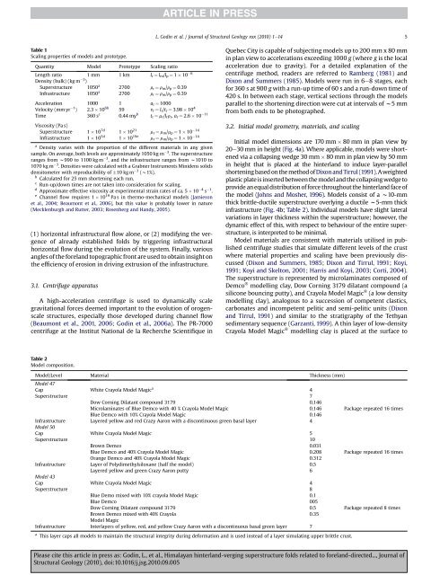
L. Godin et al. / Journal of Structural Geology xxx (2010) 1e14 5Table 1Scaling properties of models and pro<strong>to</strong>type.Quantity Model Pro<strong>to</strong>type Scaling ratioLength ratio 1 mm 1 km l r ¼ l m /l p ¼ 1 10 6Density (bulk) (kg m 3 )Superstructure 1050 a 2700 r r ¼ r m /r p ¼ 0.39Infrastructure 1050 a 2700 r r ¼ r m /r p ¼ 0.39Acceleration 1000 1 a r ¼ 1000Velocity (mm yr 1 ) 2.3 10 6b 59 v r ¼ l r /t r ¼ 3.98 10 4Time 360 s c 0.44 my b t r ¼ m r /l r r r , a r ¼ 2.6 10 11Viscosity (Pa s)Superstructure 1 10 7d 1 10 21 m r ¼ m m /m p ¼ 1 10 14Infrastructure 1 10 5d 1 10 19e m r ¼ m m /m p ¼ 1 10 14a Density varies with the proportion of the different materials in any givensample. On average, both levels are approximately 1050 kg m 3 . The <strong>superstructure</strong>ranges from w990 <strong>to</strong> 1100 kg m 3 , and the infrastructure ranges from w1010 <strong>to</strong>1070 kg m 3 . Densities were calculated with a Grabner Instruments Minidens solidsdensi<strong>to</strong>meter with reproducibility of 10 kg m 3 (w1%).b Calculated for 25 mm shortening each run.c Run-up/down times are not taken in<strong>to</strong> consideration for scaling.d Approximate effective viscosity at experimental strain rates of ca. 5 10 4 s 1 .e Channel flow requires 1 10 19 Pa s in thermo-mechanical models (Jamiesonet al., 2004; Beaumont et al., 2006), but this value is probably lower in nature(Mecklenburgh and Rutter, 2003; Rosenberg and Handy, 2005).(1) horizontal infrastructural flow alone, or (2) modifying the vergenceof already established <strong>folds</strong> by triggering infrastructuralhorizontal flow during the evolution of the system. Finally, variousangles of the foreland <strong>to</strong>pographic front are used <strong>to</strong> obtain insight onthe efficiency of erosion in driving extrusion of the infrastructure.3.1. Centrifuge apparatusA high-acceleration centrifuge is used <strong>to</strong> dynamically scalegravitational forces deemed important <strong>to</strong> the evolution of orogenscalestructures, especially those developed during channel flow(Beaumont et al., 2001, 2006; Godin et al., 2006a). The PR-7000centrifuge at the Institut National de la Recherche Scientifique inQuebec City is capable of subjecting models up <strong>to</strong> 200 mm x 80 mmin plan view <strong>to</strong> accelerations exceeding 1000 g (where g is the localacceleration due <strong>to</strong> gravity). For a detailed explanation of thecentrifuge method, readers are referred <strong>to</strong> Ramberg (1981) andDixon and Summers (1985). Models were run in 6e8 stages, eachfor 360 s at 900 g with a run-up time of 60 s and a run-down time of420 s. In between each stage, vertical sections through the modelsparallel <strong>to</strong> the shortening direction were cut at intervals of w5mmfrom both ends <strong>to</strong> be pho<strong>to</strong>graphed.3.2. Initial model geometry, materials, and scalingInitial model dimensions are 170 mm 80 mm in plan view by20e30 mm in height (Fig. 4a). Where applicable, models were shortenedvia a collapsing wedge 30 mm 80 mm in plan view by 50 mmin height that is placed at the <strong>hinterland</strong> <strong>to</strong> induce layer-parallelshortening based on the method of Dixon and Tirrul (1991).Aweightedplastic plate is inserted between the model and the collapsing wedge <strong>to</strong>provide an equal distribution of force throughout the <strong>hinterland</strong> face ofthe model (Johns and Mosher, 1996). Models consist of a w10-mmthick brittle-ductile <strong>superstructure</strong> overlying a ductile w5-mm thickinfrastructure (Fig. 4b; Table 2). Individual models have slight lateralvariations in layer thickness within the <strong>superstructure</strong>; however, thedynamic effect of this, with respect <strong>to</strong> behaviour of the entire <strong>superstructure</strong>,is interpreted <strong>to</strong> be minimal.Model materials are consistent with materials utilised in publishedcentrifuge studies that simulate different levels of the crustwhere material properties and scaling have been previously discussed(Dixon and Summers, 1985; Dixon and Tirrul, 1991; Koyi,1991; Koyi and Skel<strong>to</strong>n, 2001; Harris and Koyi, 2003; Corti, 2004).The <strong>superstructure</strong> is represented by microlaminates composed ofDemco Ò modelling clay, Dow Corning 3179 dilatant compound (asilicone bouncing putty), and Crayola Model Magic Ò (a low densitymodelling clay), analogous <strong>to</strong> a succession of competent clastics,carbonates and incompetent pelitic and semi-pelitic units (Dixonand Tirrul, 1991) and similar <strong>to</strong> the stratigraphy of the Tethyansedimentary sequence (Garzanti, 1999). A thin layer of low-densityCrayola Model Magic Ò modelling clay is placed at the surface <strong>to</strong>Table 2Model composition.Model/Level Material Thickness (mm)Model 47Cap White Crayola Model Magic a 4Superstructure 7Dow Corning Dilatant compound 3179 0.146Microlaminates of Blue Demco with 40 % Crayola Model Magic 0.146 Package repeated 16 timesBlue Demco with 10% Crayola Model Magic 0.146Infrastructure Layered yellow and red Crazy Aaron with a discontinuous green basal layer 4Model 50Cap White Crayola Model Magic 5Superstructure 10Brown Demco 0.031Blue Demco and 40% Crayola Model Magic 0.208 Package repeated 16 timesOrange Demco and 40% Crayola Model Magic 0.312Infrastructure Layer of Polydimethylsiloxane (half the model) 0.5Layered yellow and green Crazy Aaron putty 6Model 43Cap White Crayola Model Magic 4Superstructure 8Blue Demo mixed with 10% crayola Model Magic 0.1Blue Demco 005Dow Corning Dilatant compound 3179 0.5Package repeated 8 timesBrown Demco mixed with 40% Crayola0.35Model MagicInfrastructure Interlayers of yellow, red, and yellow Crazy Aaron with a discontinuous basal green layer 7a This layer caps all models <strong>to</strong> maintain the structural integrity during deformation and is used instead of a layer simulating upper brittle crust.Please cite this article in press as: Godin, L., et al., <strong>Himalayan</strong> <strong>hinterland</strong>-<strong>verging</strong> <strong>superstructure</strong> <strong>folds</strong> <strong>related</strong> <strong>to</strong> foreland-directed..., Journal ofStructural Geology (2010), doi:10.1016/j.jsg.2010.09.005


