Operating Manual - KLARO GmbH
Operating Manual - KLARO GmbH
Operating Manual - KLARO GmbH

You also want an ePaper? Increase the reach of your titles
YUMPU automatically turns print PDFs into web optimized ePapers that Google loves.
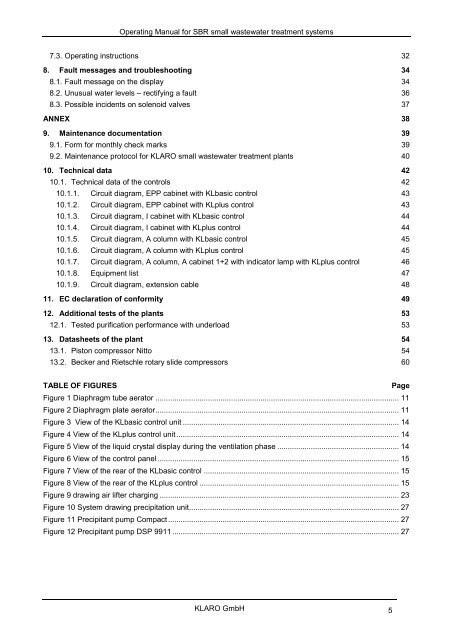
<strong>Operating</strong> <strong>Manual</strong> for SBR small wastewater treatment systems7.3. <strong>Operating</strong> instructions 328. Fault messages and troubleshooting 348.1. Fault message on the display 348.2. Unusual water levels – rectifying a fault 368.3. Possible incidents on solenoid valves 37ANNEX 389. Maintenance documentation 399.1. Form for monthly check marks 399.2. Maintenance protocol for <strong>KLARO</strong> small wastewater treatment plants 4010. Technical data 4210.1. Technical data of the controls 4210.1.1. Circuit diagram, EPP cabinet with KLbasic control 4310.1.2. Circuit diagram, EPP cabinet with KLplus control 4310.1.3. Circuit diagram, I cabinet with KLbasic control 4410.1.4. Circuit diagram, I cabinet with KLplus control 4410.1.5. Circuit diagram, A column with KLbasic control 4510.1.6. Circuit diagram, A column with KLplus control 4510.1.7. Circuit diagram, A column, A cabinet 1+2 with indicator lamp with KLplus control 4610.1.8. Equipment list 4710.1.9. Circuit diagram, extension cable 4811. EC declaration of conformity 4912. Additional tests of the plants 5312.1. Tested purification performance with underload 5313. Datasheets of the plant 5413.1. Piston compressor Nitto 5413.2. Becker and Rietschle rotary slide compressors 60TABLE OF FIGURESPageFigure 1 Diaphragm tube aerator .................................................................................................................... 11Figure 2 Diaphragm plate aerator.................................................................................................................... 11Figure 3 View of the KLbasic control unit ....................................................................................................... 14Figure 4 View of the KLplus control unit .......................................................................................................... 14Figure 5 View of the liquid crystal display during the ventilation phase .......................................................... 14Figure 6 View of the control panel ................................................................................................................... 15Figure 7 View of the rear of the KLbasic control ............................................................................................. 15Figure 8 View of the rear of the KLplus control ............................................................................................... 15Figure 9 drawing air lifter charging .................................................................................................................. 23Figure 10 System drawing precipitation unit.................................................................................................... 27Figure 11 Precipitant pump Compact .............................................................................................................. 27Figure 12 Precipitant pump DSP 9911 ............................................................................................................ 27<strong>KLARO</strong> <strong>GmbH</strong> 5