R7140G,L,M Burner Control Modules - ES2 Inc.
R7140G,L,M Burner Control Modules - ES2 Inc.
R7140G,L,M Burner Control Modules - ES2 Inc.
- No tags were found...

You also want an ePaper? Increase the reach of your titles
YUMPU automatically turns print PDFs into web optimized ePapers that Google loves.
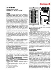
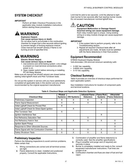
<strong>R7140G</strong>,L,M BURNER CONTROL MODULESSYSTEM CHECKOUTIMPORTANTPerform all Static Checkout Procedures in theapplicable relay module installation instructionsbefore starting these procedures.WARNINGExplosion Hazard.Can cause serious injury or death.Do not allow fuel to accumulate in the combustionchamber for longer than a few seconds without ignitingto prevent danger of forming explosive mixture.Close manual fuel shutoff valve(s) if flame is notburning at end of specified time.WARNINGElectric Shock Hazard.Can cause serious injury or death.1. Use extreme care while testing system. Line voltageis present on most terminal connections whenpower is on.2. Open master switch before removing or installingR7140 Relay Module.Make sure all manual fuel shutoff valve(s) are closed beforestarting initial lightoff check and Pilot Turndown tests.Do not put the system in service until you have satisfactorilycompleted all applicable tests in this section and any othersrecommended by the original equipment manufacturer.Limit trial for pilot to ten seconds. Limit the attempt to lightmain burner to two seconds after fuel reaches burner nozzle.Do not exceed manufacturer nominal lightoff time.CAUTIONEquipment Malfunction or Damage Hazard.<strong>Inc</strong>orrect wiring can cause equipment damage.Each relay module type is unique. Using existingwiring on a relay module change can cause equipmentdamage.IMPORTANT1. If the system fails to perform properly, refer to theTroubleshooting section.2. Repeat all required Checkout tests after alladjustments are made. All tests must be satisfiedwith the flame detector(s) in their final position.Equipment RecommendedS7800A Keyboard Display ModuleVolt-ohmmeter (1M ohm/volt minimum sensitivity) with:• 0-300 Vac capability.• 0-6000 ohm capability.• 0-10 Vdc capability.Checkout SummaryTable 9 provides an overview of checkout steps performed foreach applicable system.See Installation Instructions for location of component partsand terminal locations.Table 9. Checkout Steps and Applicable Detection Systems.Checkout StepPilotedSystems DSI SystemsInfrared FlameDetectorsFlame RodSystemsUltravioletFlame DetectorsPreliminary Inspection X X X X XFlame Signal Measurement X X X X XInitial Lightoff Check for Proved PilotXInitial Lightoff Check for Direct Spark IgnitionXPilot Turndown TestXIgnition Interference TestXHot Refractory Saturation TestXHot Refractory Hold-in Test X X X X XIgnition Spark PickupXResponse to Other Ultraviolet SourcesXFlame Signal with Hot Combustion Chamber X X X X XSafety Shutdown Tests X X X X XPreliminary InspectionPerform the following inspections to avoid common problems.Make certain that:1. Wiring connections are correct and all terminal screwsare tight.2. Flame detector(s) is clean, installed and positionedproperly. Consult the applicable Instructions.3. Combination of amplifier and flame detector(s) iscorrectly used. See the amplifier specifications.4. Plug-in amplifier and purge card (if required) aresecurely in place.5. <strong>Burner</strong> is completely installed and ready to fire; consultequipment manufacturer instructions. Fuel lines arepurged of air.6. Combustion chamber and flues are clear of fuel and fuelvapor.27 66-1153—2