<strong>R7140G</strong>,L,M BURNER CONTROL MODULESIMPORTANT1. Wiring connections for the relay modules are unique;therefore, refer to Fig. 4–11 or the correctSpecifications for proper subbase wiring, andsequence charts.2. Wiring must comply with all applicable codes,ordinances and regulations.3. Wiring must comply with NEC Class 1 (Line Voltage)wiring.4. Loads connected to the R7140 must not exceedthose listed in the Specifications; see Table 3 and 4.5. Limits and interlocks must be rated to simultaneouslycarry and break current to the ignition transformer,pilot valve, and main fuel valve(s).6. All external timers must be listed or componentrecognized by authorities who have jurisdiction forthe specific purpose for which they are used.7. For on-off gas-fired systems, some authorities whohave jurisdiction prohibit the wiring of any limit oroperating contacts in series between the flamesafeguard control and the main fuel valve(s).8. Two Flame Detectors can be connected in parallelwith the exception of flame detectors C7015, C7927,C7935, C7915, C7961, and C7962.9. This equipment generates, uses and can radiateradio frequency energy and, if not installed and usedin accordance with the instructions, may causeinterference to radio communications. It has beentested and found to comply with the limits for aClass B computing device of Part 15 of FCC ruleswhich are designed to provide reasonable protectionagainst such interference when operated in acommercial environment. Operation of thisequipment in a residential area may causeinterference; in which case, the users at their ownexpense may be required to take whatevermeasures are required to correct this interference.10.This digital apparatus does not exceed the Class Blimits for radio noise for digital apparatus set out inthe Radio Interference Regulations of the CanadianDepartment of Communications.LocationHumidityInstall the relay module where the relative humidity neverreaches the saturation point. The relay module is designed tooperate in a maximum 85 percent relative humiditycontinuous, noncondensing moisture environment.Condensing moisture may cause a safety shutdown.VibrationDo not install the relay module where it could be subjected tovibration in excess of 0.5G continuous maximum vibration.WeatherThe relay module is not designed to be weathertight.When installed outdoors, protect the relay module using anapproved weathertight enclosure.Mounting Wiring Subbase1. Mount the subbase in any position except horizontallywith the quadfurcated contacts pointing down. Thestandard vertical position is recommended. Any otherposition decreases the maximum ambient temperaturerating.2. Select a location on a wall, burner, or electrical panel.The Q520A can be mounted directly in the controlcabinet. Be sure to allow adequate clearance forservicing, installation, access or removal of the R7140,Expanded Annunciator, Keyboard Display Module,flame amplifier, flame amplifier signal voltage probes,Run/Test Switch, electrical signal voltage probes andelectrical field connections.3. For surface mounting, use the back of the subbase as atemplate to mark the four screw locations. Drill the pilotholes.4. Securely mount the subbase using four no. 6 screws.Wiring SubbaseWARNINGElectrical Shock Hazard.Can cause serious injury, death or equipmentdamage.Disconnect the power supply before beginninginstallation to prevent electrical shock, equipmentand control damage. More than one power supplydisconnect may be required.1. For proper subbase wiring, internal drawings, andsequence check charts, refer to Fig. 5, 6, 7, 8, 9 and 11.2. Disconnect the power supply from the main disconnectbefore beginning installation to prevent electrical shockand equipment damage. More than one disconnect maybe required.3. All wiring must comply with all applicable electricalcodes, ordinances and regulations. Wiring, whererequired, must comply with NEC, Class 1 (Line Voltage)wiring.a. Follow recommended wire size and type.b. Follow recommended grounding practices.4. Recommended wire routing of leadwires:a. Do not run high voltage ignition transformer wires inthe same conduit with the flame detector.b. Do not route flame detector leadwires in conduitwith line voltage circuits.c. Enclose flame detector leadwires without armorcable in metal cable or conduit.d. Follow directions in flame detector Instructions.5. Maximum wire lengths follow:a. R7140 leadwires—The maximum length of leadwireis 300 feet to terminal inputs (<strong>Control</strong>, Pre-IgnitionInterlock, Running/Lockout Interlock, High FireSwitch and Low Fire Switch).b. Flame Detector leadwires—The maximum flamesensor leadwire length is limited by the flame signalstrength.c. Remote Reset leadwires—The maximum length ofwire is 1000 feet to a Remote Reset push button.6. Make sure loads do not exceed the terminal ratings.Refer to the label on the R7140 or to the ratings in Table3 and 4.66-1153—2 6
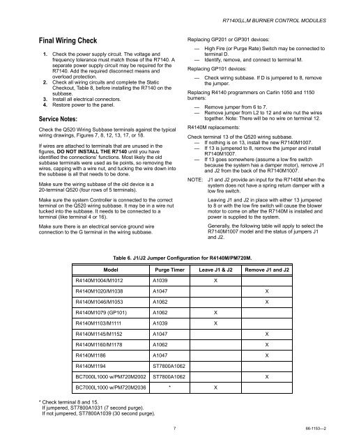
<strong>R7140G</strong>,L,M BURNER CONTROL MODULESFinal Wiring Check1. Check the power supply circuit. The voltage andfrequency tolerance must match those of the R7140. Aseparate power supply circuit may be required for theR7140. Add the required disconnect means andoverload protection.2. Check all wiring circuits and complete the StaticCheckout, Table 8, before installing the R7140 on thesubbase.3. Install all electrical connectors.4. Restore power to the panel.Service Notes:Check the Q520 Wiring Subbase terminals against the typicalwiring drawings, Figures 7, 8, 12, 13, 17, or 18.If wires are attached to terminals that are unused in thefigures, DO NOT INSTALL THE R7140 until you haveidentified the connections’ functions. Most likely the oldsubbase terminals were used as tie points, so removing thewires, capping with a wire nut, and tucking the wire down intothe subbase is all that needs to be done.Make sure the wiring subbase of the old device is a20-terminal Q520 (four rows of 5 terminals).Make sure the system <strong>Control</strong>ler is connected to the correctterminal on the Q520 wiring subbase. It may be in a wire nuttucked into the subbase. It needs to be connected to aterminal (like terminal 4 or 16).Make sure there is an electrical service ground wireconnection to the G terminal in the wiring subbase.Replacing GP201 or GP301 devices:— High Fire (or Purge Rate) Switch may be connected toterminal D.— Identify, remove, and connect to terminal M.Replacing GP101 devices:— Check wiring subbase. If D is jumpered to 8, removethe jumper.Replacing R4140 programmers on Carlin 1050 and 1150burners:— Remove jumper from 6 to 7.— Remove jumper from L2 to 12 and wire nut the wirestogether. Note: There will be no wire on terminal 12.R4140M replacements:Check terminal 13 of the Q520 wiring subbase.— If nothing is on 13, install the new R7140M1007.— If 13 is jumpered to 8, remove the jumper and installR7140M1007.— If 13 goes somewhere (assume a low fire switchbecause the system has a damper motor), remove J1and J2 from the back of the R7140M1007.NOTE: J1 and J2 provide an input for the R7140M when thesystem does not have a spring return damper with alow fire switch.Leaving J1 and J2 in place with either 13 jumperedto 8 or with the low fire switch will cause the blowermotor to come on after the R7140M is installed andpower is supplied to the system.Generally, the following table will apply to select theR7140M1007 model and the status of jumpers J1and J2.Table 6. J1/J2 Jumper Configuration for R4140M/PM720M.Model Purge Timer Leave J1 & J2 Remove J1 and J2R4140M1004/M1012 A1039 XR4140M1020/M1038 A1047 XR4140M1046/M1053 A1062 XR4140M1079 (GP101) A1062 XR4140M1103/M1111 A1039 XR4140M1145/M1152 A1047 XR4140M1160/M1178 A1062 XR4140M1186 A1047 XR4140M1194ST7800A1062BC7000L1000 w/PM720M2002 ST7800A1062 XBC7000L1000 w/PM720M2036 * X* Check terminal 8 and 15.If jumpered, ST7800A1031 (7 second purge).If not jumpered, ST7800A1039 (30 second purge).7 66-1153—2
- Page 3 and 4: R7140G,L,M BURNER CONTROL MODULESTa
- Page 5: R7140G,L,M BURNER CONTROL MODULESTa
- Page 9 and 10: R7140G,L,M BURNER CONTROL MODULESL1
- Page 11 and 12: R7140G,L,M BURNER CONTROL MODULESFO
- Page 13 and 14: R7140G,L,M BURNER CONTROL MODULESLE
- Page 15 and 16: R7140G,L,M BURNER CONTROL MODULESL1
- Page 17 and 18: R7140G,L,M BURNER CONTROL MODULESFO
- Page 19 and 20: R7140G,L,M BURNER CONTROL MODULESL1
- Page 21 and 22: R7140G,L,M BURNER CONTROL MODULES4F
- Page 23 and 24: R7140G,L,M BURNER CONTROL MODULESNo
- Page 25 and 26: R7140G,L,M BURNER CONTROL MODULESST
- Page 27 and 28: R7140G,L,M BURNER CONTROL MODULESSY
- Page 29 and 30: R7140G,L,M BURNER CONTROL MODULESc.
- Page 31 and 32: R7140G,L,M BURNER CONTROL MODULESHo