SIIT Commemorative Publication (10 Years of International ...
SIIT Commemorative Publication (10 Years of International ...
SIIT Commemorative Publication (10 Years of International ...
- No tags were found...
You also want an ePaper? Increase the reach of your titles
YUMPU automatically turns print PDFs into web optimized ePapers that Google loves.
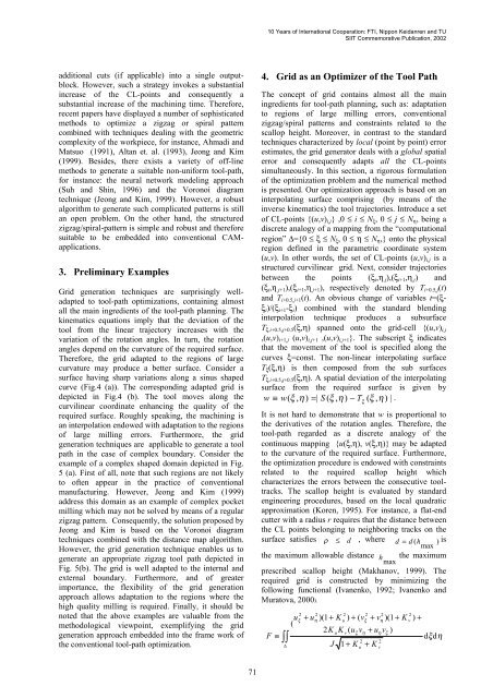
<strong>10</strong> <strong>Years</strong> <strong>of</strong> <strong>International</strong> Cooperation: FTI, Nippon Keidanren and TU<strong>SIIT</strong> <strong>Commemorative</strong> <strong>Publication</strong>, 2002additional cuts (if applicable) into a single outputblock.However, such a strategy invokes a substantialincrease <strong>of</strong> the CL-points and consequently asubstantial increase <strong>of</strong> the machining time. Therefore,recent papers have displayed a number <strong>of</strong> sophisticatedmethods to optimize a zigzag or spiral patterncombined with techniques dealing with the geometriccomplexity <strong>of</strong> the workpiece, for instance, Ahmadi andMatsuo (1991), Altan et. al. (1993), Jeong and Kim(1999). Besides, there exists a variety <strong>of</strong> <strong>of</strong>f-linemethods to generate a suitable non-uniform tool-path,for instance: the neural network modeling approach(Suh and Shin, 1996) and the Voronoi diagramtechnique (Jeong and Kim, 1999). However, a robustalgorithm to generate such complicated patterns is stillan open problem. On the other hand, the structuredzigzag/spiral-pattern is simple and robust and thereforesuitable to be embedded into conventional CAMapplications.3. Preliminary ExamplesGrid generation techniques are surprisingly welladaptedto tool-path optimizations, containing almostall the main ingredients <strong>of</strong> the tool-path planning. Thekinematics equations imply that the deviation <strong>of</strong> thetool from the linear trajectory increases with thevariation <strong>of</strong> the rotation angles. In turn, the rotationangles depend on the curvature <strong>of</strong> the required surface.Therefore, the grid adapted to the regions <strong>of</strong> largecurvature may produce a better surface. Consider asurface having sharp variations along a sinus shapedcurve (Fig.4 (a)). The corresponding adapted grid isdepicted in Fig.4 (b). The tool moves along thecurvilinear coordinate enhancing the quality <strong>of</strong> therequired surface. Roughly speaking, the machining isan interpolation endowed with adaptation to the regions<strong>of</strong> large milling errors. Furthermore, the gridgeneration techniques are applicable to generate a toolpath in the case <strong>of</strong> complex boundary. Consider theexample <strong>of</strong> a complex shaped domain depicted in Fig.5 (a). First <strong>of</strong> all, note that such regions are not likelyto <strong>of</strong>ten appear in the practice <strong>of</strong> conventionalmanufacturing. However, Jeong and Kim (1999)address this domain as an example <strong>of</strong> complex pocketmilling which may not be solved by means <strong>of</strong> a regularzigzag pattern. Consequently, the solution proposed byJeong and Kim is based on the Voronoi diagramtechniques combined with the distance map algorithm.However, the grid generation technique enables us togenerate an appropriate zigzag tool path depicted inFig. 5(b). The grid is well adapted to the internal andexternal boundary. Furthermore, and <strong>of</strong> greaterimportance, the flexibility <strong>of</strong> the grid generationapproach allows adaptation to the regions where thehigh quality milling is required. Finally, it should benoted that the above examples are valuable from themethodological viewpoint, exemplifying the gridgeneration approach embedded into the frame work <strong>of</strong>the conventional tool-path optimization.4. Grid as an Optimizer <strong>of</strong> the Tool PathThe concept <strong>of</strong> grid contains almost all the mainingredients for tool-path planning, such as: adaptationto regions <strong>of</strong> large milling errors, conventionalzigzag/spiral patterns and constraints related to thescallop height. Moreover, in contrast to the standardtechniques characterized by local (point by point) errorestimates, the grid generator deals with a global spatialerror and consequently adapts all the CL-pointssimultaneously. In this section, a rigorous formulation<strong>of</strong> the optimization problem and the numerical methodis presented. Our optimization approach is based on aninterpolating surface comprising (by means <strong>of</strong> theinverse kinematics) the tool trajectories. Introduce a set<strong>of</strong> CL-points {(u,v) i,j } ,0 ≤ i ≤ N ξ , 0 ≤ j ≤ N η , being adiscrete analogy <strong>of</strong> a mapping from the “computationalregion” ∆={0 ≤ ξ ≤ N ξ , 0 ≤ η ≤ N η ,} onto the physicalregion defined in the parametric coordinate system(u,v). In other words, the set <strong>of</strong> CL-points (u,v) i,j is astructured curvilinear grid. Next, consider trajectoriesbetween the points (ξ i ,η ,j ),(ξ i+1 ,η ,j ) and(ξ i ,η ,j+1 ),(ξ i+1 ,η ,j+1 ), respectively denoted by T i+0.5,j (t)and T i+0.5,j+1 (t). An obvious change <strong>of</strong> variables t=(ξξi )/(ξ i+1 -ξ i ) combined with the standard blendinginterpolation technique produces a subsurfaceT ξ,i+0.5,j+0.5 (ξ,η) spanned onto the grid-cell {(u,v) i,j,(u,v) i+1,j (u,v) i,j+1 ,(u,v) i,j+1 }. The subscript ξ indicatesthat the movement <strong>of</strong> the tool is specified along thecurves ξ=const. The non-linear interpolating surfaceT ξ (ξ,η) is then composed from the sub surfacesT ξ,i+0.5,j+0.5 (ξ,η). A spatial deviation <strong>of</strong> the interpolatingsurface from the required surface is given byw ≡ w( ξ , η)= | S ( ξ , η ) − T ( ξ , η ) | .It is not hard to demonstrate that w is proportional tothe derivatives <strong>of</strong> the rotation angles. Therefore, thetool-path regarded as a discrete analogy <strong>of</strong> thecontinuous mapping {u(ξ,η), v(ξ,η)} may be adaptedto the curvature <strong>of</strong> the required surface. Furthermore,the optimization procedure is endowed with constraintsrelated to the required scallop height whichcharacterizes the errors between the consecutive tooltracks.The scallop height is evaluated by standardengineering procedures, based on the local quadraticapproximation (Koren, 1995). For instance, a flat-endcutter with a radius r requires that the distance betweenthe CL points belonging to neighboring tracks on thesurface satisfies ρ ≤ d , where d = d (h ) isthe maximum allowable distance h maxξmaxthe maximumprescribed scallop height (Makhanov, 1999). Therequired grid is constructed by minimizing thefollowing functional (Ivanenko, 1992; Ivanenko andMuratova, 2000).F ≡∫∫u(2ξ+ u2η)(1 + K2K2u) + ( v2∆ J 1 + Ku+uK ( u vvξ2ξη+ v2η+ u v )Kη2v)(1 + Kξ2v) +dξdη71


