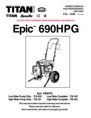
<strong>Admiral</strong> 245-556 Fluid Pump Assembly12345678910111212131424232218171615ItemNo.PartNo.DescriptionQTY.1 245-907 Block, pump 12 240-001 Packing set, Poly/Lthr. 13 245-005 Packing spring, upper 14 245-013 Retainer, spring 15 892-323 O-ring, Telfon 16 245-012 Cylinder 17 920-103 Ball, S.S. 18 245-020 Retainer, spring 19 245-014 Spring, packing 110 240-001 Packing set, Poly/Lthr 111 241-007 Seat, piston 112 240-022 Cage, ball 112a 241-109 Pin, ball stop 113 891-403 O-ring, Teflon 114 892-281 O-ring, Buna 115 245-018 Valve, foot 116 314-180 Ball, S.S. 117 245-021 Retainer, cage 118 245-009 Rod, displacement 1ItemNo.PartNo.Description142-10419 870-401 Nut 220 870-004 Washer 621 140-016 Stanchion 222 245-109 Roll pin 123 442-959 Connecting rod 124 138-007 Nut, coupling ** Not included in this assemblyDisplacementRod AreaStroke Length Displacement Volume /StrokeDisplacement Volume / 40 Cycles/ 80 StrokesIN 2 CM 2 IN CM IN 3 CM 3 LITER IN 3 GAL. CM 3 LITER2.08 13.42 4 10.2 8.38 137.32 0.137 670 2.9 10.986 11MotorSelectionMotor Pumpratio850 Series 30:124 © Titan Tool Inc. All rights reserved.
245-556 Fluid Pump Service Informationimportant: Use of non-Titan manufactured service partsmay void warranty.The 245 Series Pump should receive a routine servicing afterapproximately 1000 hours of use or earlier if there is excessiveleakage from the top packing, or if pump strokes become fasteron one stroke or another. The use of Titan Lubrisolv Part #310-200 is recommended as an upper packing lubricant. donot substitute oil, water or solvent for an upper packinglubricant.Disassembly Procedure1. Test pump before disassembly. Follow test procedure inTroubleshooting Guide - Fluid Section.2. Remove siphon hose assembly.3. Remove stanchion nuts (19) and washers (20).4. If the fluid section is connected to an air motor, hold the airmotor piston rod at the wrench flats and unthread couplingnut (24) to separate pump from motor.If the fluid section is connected to a hydraulic motor,remove allen set screw between the two flats on hydraulicmotor rod. Hold the hydraulic motor rod at the wrenchflats and unthread coupling nut (24) to separate pumpfrom hydraulic motor.important: Never use a pipe wrench, pliers, etc. on thechrome part of hydraulic, air or fluid section rod.5. Remove roll pin (22) or jam nut on connecting rod (23).Remove connecting rod (23) from displacement rod (18).6. Unthread and remove foot valve (15).7. Remove Teflon O-ring (13), Buna O-ring (14), ball cageretainer (17), ball cage (12) and ball (16).8. Remove cylinder (6).9. Remove displacement rod (18).10. Place piston seat (11) in a vise and use a wrench on theflats to remove the displacement rod (18) from the pistonseat (11).11. Remove lower packing set (10), spring (9), spring retainer(8) and ball (7).12. Remove upper spring retainer (4), spring (3), Teflon O-ring(5) and packing set (2).13. Clean and inspect all parts. Inspect rod’s and cylinder’shard chrome for grooves, dents or worn areas. Replace ifhard chrome is damaged. Inspect valve seats and replaceif cracked or worn.Reassembly Procedure1. Insert new upper packing set (2) into pump block (1)important: Peak of “V” packings must point upwards onreassembly.2. Insert upper spring (3); small end of spring must go towardthe packing set.3. Insert spring retainer (4) and new O-ring (5) into pumpblock (1).important: Lubricate all O-rings before assembly.4. Place new lower packing set (2) over piston seat (11).important: Peak of “V” must point downward onreassembly.5. Replace spring (9), spring retainer (8) and ball (7) onpiston seat (13).6. Thread piston seat back onto displacement rod (18).important: Use Loctite on clean threads.7. Insert displacement rod assembly through upper packingset (2) in pump block (1).8. Thread cylinder (6) back into into pump block (1).9. Insert new ball (16), ball cage (12), ball cage retainer (17)new Buna O-ring (14) and new Teflon O-ring (13).important: Lubricate all O-rings into foot valve (15).NOTE: Ball cage pin (12a) to be in lower position unlesspump is to be used for heavy block filler orroofing materials.10. Thread foot valve (15) back into cylinder (6).11. Place connecting rod (23) through coupling nut (24) andthread connecting rod (23) into displacement rod (18).12. Replace roll pin (23) into displacement rod (18).NOTE: It is not necessary to overtighten foot valve andcylinder into pump block. O-ring seals performsealing function without excessive tightening.Full thread engagement is sufficient. The footvalve (16) may be rotated back up to 1/2 turn fromfull engagement for convenient hose position.For siphon hose attachment, it is critically important thatthe thread of the siphon hose fit snugly into the foot valvewith the hose assembly couplings Teflon-taped and sealedto prevent air inlet leakage.Service KitsItemNo.PartNo.Pump service kit, minorDescription2 240-001 Packing set, upper,Poly/Lthr2 240-101 Packing set, upper,Leather2 240-201 Packing set, upper,Teflon245-0501245-0511245-0525 892-323 O-ring, Teflon 1 1 17 920-103 Ball 1 1 110 240-001 Packing set, lower, 1Poly/Lthr10 240-101 Packing set, lower,1leather10 240-201 Packing set, lower,1Teflon13 891-403 O-ring, Teflon 1 1 114 182-007 O-ring, Buna 1 1 116 314-180 Ball 1 1 1426-051 Loctite Sealant 1 1 1ItemNo.PartNo.Pump service kit, majorDescription245-500245-050 Minor kit 1245-501245-051 Minor kit 11245-502245-052 Minor kit 16 245-012 Cylinder 1 1 19 245-014 Spring, packing 1 1 118 245-009 Displacement rod 1 1 1© Titan Tool Inc. All rights reserved. 25