Curved-Lid Tool Chest, Pt. 2 - Woodsmith Woodworking Seminars
Curved-Lid Tool Chest, Pt. 2 - Woodsmith Woodworking Seminars
Curved-Lid Tool Chest, Pt. 2 - Woodsmith Woodworking Seminars
- No tags were found...

You also want an ePaper? Increase the reach of your titles
YUMPU automatically turns print PDFs into web optimized ePapers that Google loves.
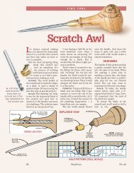
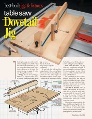
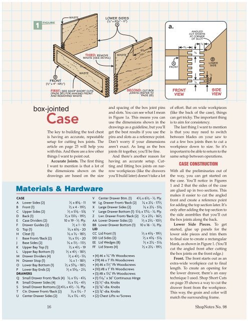
1 FIGUREWASTELOWER SIDES(!/2" x 8#/8" - 11")Aa.ANGLEDCUT STARTSAT CORNEROF SLOTTHIRD: REMOVEWASTE (SEE DETAIL)WASTE5&/8AFRONT1!/2#/4!/2BLOWERSIDEBFRONT(!/2" x 4" -19!/2")WASTEFIRST: SEE SHOP SHORT CUTS(PAGE 35) FOR MAKING FRONTAND REMOVING WASTESECOND: CUT BOXJOINTS (REFER TOPAGE 25)FRONTVIEW!/2!/4SIDEVIEWbox-jointedCaseThe key to building the tool chestis having an accurate, repeatablesetup for cutting box joints. Thearticle on page 25 will help youwith this. And there are a few otherthings I want to point out.Accurate Joints. The first thingI want to mention is that a lot ofthe dimensions shown on thedrawings are based on the sizeMaterials & Hardwareand spacing of the box joint pinsand slots. You can see what I meanin Figure 1a. This means you canuse the dimensions shown in thedrawings as a guideline, but you’llget the best results if you use thepins and slots as a reference point.Don’t worry if your dimensionsaren’t exact. As long as the boxjoints fit together, you’ll be fine.And there’s another reason forhaving an accurate setup. Cuttingand fitting box joints on narrowworkpieces (like the drawersyou’ll build later) doesn’t take a lotV Center Drawer Btm. (1) 4 1 / 4 x 6 3 / 4 - 1 / 4 Ply.CASEU Center Drawer Sides (2) 1/ 4 x 1 1 / 4 - 4 1 / 2 • (2) <strong>Chest</strong> Lifts w/ScrewsA Lower Sides (2) 1 / 2 x 8 3 / 8 - 11 W Lg. Drawer Front/Back (2) 1 / 4 x 2 1 / 4 - 17 1 / 2B Front (1) 1 / 2 x 4 - 19 1 / 2 X Large Drawer Sides (2) 1 / 4 x 2 1 / 4 - 5 3 / 8C Upper Sides (2) 1 / 2 x 5 3 / 8 - 5 7 / 8 Y Large Drawer Bottom (1) 5 1 / 8 x 17 1 / 4 - 1 / 4 Ply.D Back (1) 1 / 2 x 13 3 / 4 - 19 1 / 2 Z Lwr. Drawer Front/Back (2) 1 / 2 x 2 3 / 4 - 16 1 / 2E Case Dividers (2) 10 x 19 - 1 / 2 Ply. AA Lower Drawer Sides (2) 1 / 2 x 2 3 / 4 - 10 1 / 2F Drawer Guides (2) 1 / 2 x 1 - 10 BB Lower Drawer Bottom (1) 10 x 16 - 1 / 4 Ply.G Top (1) 3 / 4 x 6 3 / 8 - 20 LIDH Cleat (1) 3 / 4 x 3 / 4 - 18 1 / 2 CC <strong>Lid</strong> Front (1) 1 / 2 x 4 3 / 8 - 19 1 / 2I Base Front/Back (2) 3 / 4 x 1 1 / 2 - 20 DD <strong>Lid</strong> Sides (2) 1 / 2 x 4 3 / 8 - 5 1 / 8J Base Sides (2) 3 / 4 x 1 1 / 2 - 11 1 / 2 EE <strong>Lid</strong> Wedges (8) 1 / 2 x 2 1 / 4 - 5 1 / 8K Upper Bay Top (1) 1 / 2 x 4 1 / 2 - 19 FF <strong>Lid</strong> Staves (4) 1 / 2 x 2 1 / 4 - 19 1 / 2L Upper Bay Bottom (1) 1 / 2 x 4 1 / 2 - 18 1 / 2M Drawer Dividers (4) 1 / 2 x 4 1 / 2 - 1 1 / 4 • (4) #6 x 3 / 4" Fh WoodscrewsN Drawer Stop (1) 1 / 4 x 1 - 18 1 / 2 • (19) #6 x 1" Fh WoodscrewsO Lower Bay Bottom (1) 1/ 2 x 5 9 / 16 - 18 1 / 2 • (4) #6 x 1 1 / 2" Fh WoodscrewsP Lower Bay Ends (2) 1 / 2 x 5 5 / 16 - 2 1 / 4 • (10) #8 x 1" Fh WoodscrewsDRAWERSQ Small Drawer Front/Back (4) 1 / 4 x 1 1 / 4 - 4 3 / 4• (3) #8 x 1 1 / 4" Fh Woodscrews• (1) 1 1 / 16" x 36" Continuous HingeR Small Drawer Sides (4) 1 / 4 x 1 1 / 4 - 4 1 / 2 • (3) 1 / 2"-dia. KnobsS Small Drawer Bottoms (2) 4 1 / 4 x 4 1 / 2 - 1 / 4 Ply. • (3) 5 / 8"-dia. KnobsT Ctr. Drawer Front/Back (2) 1 / 4 x 1 1 / 4 - 7 • (2) 7 / 8"-dia. Knobsof effort. But on wide workpieces(like the back of the case), thingscan get tricky. The important thingis to aim for consistency.The last thing I want to mentionis that you may need to switchbetween blades on your saw tocut a few box joints then to cut aworkpiece down to size. So it’simportant to be able to return to thesame setup between operations.CASE CONSTRUCTIONWith all the preliminaries out ofthe way, you can get started onthe case. You’ll notice in Figures1 and 2 that the sides of the caseare glued up in two sections. Thismakes it easier to cut the angledfront and create a reference pointfor adding the top section later. It’sonly after adding the top section tothe side assmblies that you’ll cutthe box joints along the back.Lower Side Pieces. To getstarted, glue up panels for thelower side pieces and trim themto final size to create a rectangularblank, as shown in Figure 1. (You’llcut the angled front after cuttingthe box joints on the front edge.)Front. The front starts out as anextra-wide workpiece cut to finallength. To create an opening forthe lower drawer, there’s an easytechnique I used. Shop Short Cutson page 35 shows a way to cut thedrawer front from the workpiece.This way, the grain and color willmatch the surrounding frame.16 ShopNotes No. 98
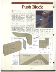
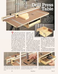
But for my tool chest, I wantedto show a little contrast betweenthe frame and drawer front. SoI discarded the center piece andmade the drawer front from a differentworkpiece that was slightlydarker. With the case front in hand,you can focus on the joinery.Cutting Box Joints. Now it’stime to set up your saw for cutting1 ⁄ 4 "-wide box joints. I started withthe side pieces then cut the matingjoints on the case front.Trimming. With these box jointscomplete, rip the case front to finalwidth. Then, with the side piecesin hand, step over to the bandsaw to cut the angled front edge.Stay outside the line and aim for asmooth, straight edge for a good fitwith the lid later on. A little sandingor trimming with a block planewill help with this.Upper Side Pieces. Now youcan glue the upper side pieces inplace to complete the side assemblies(Figure 2). If needed, trim theback edge of the side assembliesflush and set them aside for now.Back Panel. The back panel issimple. It’s just a glued-up blankcut to final size. The importantthing here is that the length of thefront and back should be the same.CUPPERSIDE(!/2" x 5&/8" - 5#/8")NOTE: ALIGNGROOVES WITHBOX JOINT SLOTS(SEE DETAILS)GROOVES IN BACKAND SIDES ARE OFFSET(SEE FIGURE 2a)LOWERSIDENOTE: CUT ALLGROOVES!/4" x !/4" DEEPCUPPERSIDEBACK(!/2" x 13#/4" - 19!/2")D3 FIGURE ers and front piece to keep thingssquare as the glue dried. Then youC!/4UPPERSIDENOTE: CUT REARBOX JOINTS AFTERGLUING UP SIDE PANELSGo ahead and cut the box joints onthe side assemblies and rear panel.I started cutting from the bottomedge of the pieces, working myway to the top edge.Now, I’ll admit that cutting thislong run of box joints can be intimidating.But if you take your timeand work on being consistent withevery cut, you shouldn’t have anyproblems getting them to fit.Grooves. To hold the case dividersand drawer bays you’ll buildlater, there are quite a few groovesyou’ll need to cut in the sides andback. The key here is to align thegrooves with the box joint slots,as shown above in Figures 2a and2b. This keeps the grooves hiddenafter the case is assembled.Dividers and Drawer Guides.The last things to do on the caseare to cut the dividers to fit thegrooves in the case and add thedrawer guides. After dry-fittingthe assembly, I glued up the sidesand back first, using the divid-can add the dividers and frontpiece to complete the assembly.Finally, the drawer guides aresimply cut to size and glued to theLOWERBACKbottom divider. The next things toSIDEwork on are the drawer bays thatfit inside the case.NOTE: CASE DIVIDERSARE MADE FROM!/2" PLYWOODDRAWERGUIDE(!/2" x 1" - 10")FCASE FRONTECASE DIVIDER(10" x 19")ECASE DIVIDER2 FIGUREa.!/4DBACK!/2a.FLOWERSIDEECASEDIVIDER!/4B4!/2ETHIS GROOVEALIGNS WITH10th NOTCHFROM TOP(OR 4!/2")b.DRAWERGUIDEFDALOWERSIDE3!/4NOTE: CASE DIVIDERSARE GLUED IN PLACEBEFORE CASE FRONTFDRAWERGUIDEFRONT VIEW!/4!/2ESIDE VIEWwww.ShopNotes.com 17
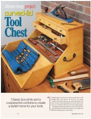
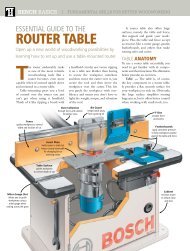
adding the top, base, &Drawer BaysNow that you’ve completed theshell of the case, you can start towork on the top and base frame.After that, you’ll add the two internalbays that will hold the drawers.The first thing you’ll work onhere is the top for the tool chest.Top and Cleat. In Figure 4, youcan see how the top is attached tothe case. There’s a cleat screwedto the underside with a tonguethat fits into the groove in theback panel. Figure 4a provides thedimensions you need to locate thecleat. You’ll be fastening the top atthe front with screws to the upperdrawer bay later. So, to allow thetop to move with seasonal changesin humidity, the tongue on thecleat floats within the groove.I cut the rabbet on the cleat atthe table saw and then fastenedthe cleat to the top. You can set this{ Attaching the Top. Accessholes in the upper drawer bay letyou screw the top in place.assembly aside for now. This makesit easier to install the drawer bayslater. Once those are in place, thenyou’ll be able to attach the top.Base Frame. At this point, youcan turn your attention to the base.It’s a simple, mitered frame, asshown in Figure 4b. I started withlong stock, then mitered pieces tolength to create the frame. Oncethe frame is glued together, you{ Lower Bay. A few screws inthe sides fasten the lower drawerbay inside the case.can rout the roundover on thetop edge. A little glue and a fewscrews are all you need to attachthe base frame to the bottom of thecase. With that done, you can setthe case upright and start on theinternal components.DRAWER BAYSThe next thing to work on is thedrawer bays. The upper bay holdsthe three smaller drawers. Thelower bay holds a single, largedrawer. Both bays are assembled4 FIGUREHfirst, then slipped into the case.GCLEATTOPYou’ll start by building the upper(#/4" x #/4" - 18!/2")(#/4" x 6#/8" - 20")C L1? bay and installing it. Then you’llbe able to attach the top and completethe lower drawer bay.SIDE VIEW a.Upper Bay. Figure 5 gives you!/8" ROUNDOVERall the information you need to!#/16GAPcut and assemble the upper bay.!/4ALLOWS#8 x 1!/4" FhFOR WOODWOODSCREWIt consists of a top and bottomMOVEMENTG TOPpiece with dividers and ends. Andthere’s a thin strip on the back side!/2that acts as a drawer stop.There’s nothing difficult aboutH!/4cutting and assembling the bay.!/4 !/4" ROUNDOVERBut one thing I want to point outJis that the top is longer than thebottom. This way, you can formLOWERSIDE b.tongues on the ends that slide intothe grooves on the case sides. YouF !/4!/4"I can see what I mean in Figure 5b.ROUNDOVERDividers and Ends. The dividersthat separate the three smallEIBASE BASE FRONT CSIDE (#/4" x 1!/2" - 20")L!/2drawers are the same size as theJends of the upper drawer bay.!/2And, to keep things simple, I usedFRONT VIEW#8 x 1" FhWOODSCREWJ butt joints for assembly. The screwsBASE SIDE2 2 (#/4" x 1!/2" - 11!/2")18 ShopNotes No. 98
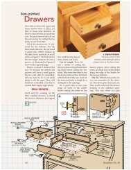
NOTE: DO NOT GLUEASSEMBLY INTO CASE#6 x 1" FhWOODSCREW5 FIGUREGLUE ASSEMBLYINTO PLACE ATFRONT EDGEONLYK UPPERMBAY TOP(!/2" x 4!/2" -19")MCUPPERLBAYDIVIDERM(!/2" x 4!/2" - 1!/4")7ML#6 x 1" Fh UPPERWOODSCREW BAY BOTTOM4#/4(!/2" x 4!/2" - 18!/2")#/8"-DIA.THROUGH HOLESFOR SCREW ACCESSIDE VIEWwill be hidden after the drawersare built and slid into place.After the drawer bay is assembled,step over to the drill press.Drill the three pilot holes in the topand access holes directly belowthem in the bottom. This willmake it easier to fit a screwdriverup through the bottom to tightenthe screws used to fasten the top inplace. The final step in the assemblyis to glue the drawer stop ontothe back side.Installation. Now you’re readyto slip the assembly into the case. Ijust used a dab of glue at the front a.to allow the bay assembly to moveCASE TOPfreely with changes in humidity.Attach the Top. With the upperK UPPER BAY TOPbay in place, you can attach the top.2!/4MTo do this, drop the cleat behind!/2!/2DRAWERthe drawer bay and slide the topDIVIDERassembly back. The tongue in theL UPPER BAY BOTTOMcleat should engage the groove inthe back panel.DRAWER STOP NI slid the top back until it wastight, then pulled it forward about1 ⁄ 16". This leaves a slight gap to bottom piece. This tongue fitsallow for movement, like you see in the groove on the back panelin Figure 5a. All you need to do (Figure 6b). Two ends completenow is fasten it down at the front the U-shaped tray to hold theedge with two screws (left photo large drawer. Here again, simpleon opposite page).butt joints do the trick and makeLower Drawer Bay. Compared assembly quick and easy.to the upper drawer bay, the lower To install the lower bay assembly,no glue is needed. Just makebay is really simple. The maindifference is you’ll need to form sure the tongue on the back slipsa.a tongue on the back edge of the into the groove on the back panel. FRONT VIEW6 FIGUREDRAWER STOP NA few screws in the end pieces atthe front edge are all you need tolock it in place (Figure 6 showsyou where to place them.)Now that both drawer bays arecomplete, you can get started settingup your table saw to make thebox joints on all the drawers.LK UPPERBAY TOPUPPER BAYBOTTOMDRAWER STOP(!/4" x 1" -18!/2")NFRONT VIEW b.CASE TOP#/8"-DIA.ACCESS HOLE#/41!/2!/4MSIDE VIEW!/4b.P#6 x 1!/2" FhWOODSCREW#6 x #/4" FhWOODSCREWLOWER PBAY END(!/2" x 5%/16" - 2!/4")OLOWERBAY BOTTOM(!/2" x 5(/16" - 18!/2")!/2!/2PLOWERBAYENDPLOWERBAYENDGAP ALLOWSFOR WOODMOVEMENTCASEBACK!/4OLOWER BAYBOTTOMOLOWER BAYBOTTOM!/4www.ShopNotes.com 19