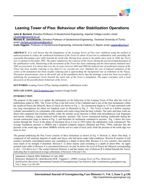
Leaning Tower of Pisa: Behaviour after Stabilization Operations
Leaning Tower of Pisa: Behaviour after Stabilization Operations
Leaning Tower of Pisa: Behaviour after Stabilization Operations
- No tags were found...

Create successful ePaper yourself
Turn your PDF publications into a flip-book with our unique Google optimized e-Paper software.
Figure 3. Cross-section in the plane <strong>of</strong> maximum inclination, situation in year 1993.Figure 4. Soil pr<strong>of</strong>ile.International Journal <strong>of</strong> Geoengineering Case Histories ©, Vol. 1, Issue 3, p. 158http://casehistories.geoengineer.org
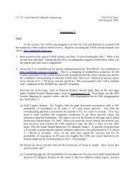
STABILIZATION WORKSThe form <strong>of</strong> motion <strong>of</strong> the foundations <strong>of</strong> the <strong>Tower</strong> during the 20th CenturyPrecise measurements begun in 1911 and show that during the twentieth century the inclination <strong>of</strong> the <strong>Tower</strong> has beenincreasing inexorably each year and the rate <strong>of</strong> tilt has doubled since the 1930's. In 1990 the increase <strong>of</strong> tilt was about 6 arcseconds per year which is equivalent to a horizontal movement at the top <strong>of</strong> about 1.5mm per year (Jamiolkowski, 2001).There has been much debate about the cause <strong>of</strong> this progressive increase in inclination. It has usually been attributed tocreep in the underlying s<strong>of</strong>t marine clay, the assumption being made that the south side was settling more than the northside. A careful study <strong>of</strong> the geodetic survey measurements going back to 1911 revealed a most surprising form <strong>of</strong> motion<strong>of</strong> the foundations which was radically different to previously held ideas. The theodolite measurements showed that the firstcornice had not moved horizontally – apart from two occasions in 1934 and the early 1970s when man had intervened.Also, precision level measurements which commenced in 1928 showed that the centre <strong>of</strong> the foundation plinth had notdisplaced vertically relative to the surrounding ground. Therefore, the rigid body motion <strong>of</strong> the <strong>Tower</strong> could only be asshown in Fig. 5, with an instantaneous centre <strong>of</strong> rotation at the level <strong>of</strong> the first cornice vertically above the centre <strong>of</strong> thefoundation. The direction <strong>of</strong> motion <strong>of</strong> points FN and FS are shown by vectors and it is clear that the foundation has beenmoving northwards with FN rising and FS sinking (Burland and Viggiani, 1994).The discovery that the motion <strong>of</strong> the <strong>Tower</strong> was as shown in Fig. 5 turned out to be crucial in four respects:1. The form <strong>of</strong> motion is consistent with the phenomenon <strong>of</strong> ‘leaning instability’ rather than an iminent bearingcapacity failure (Hambly, 1985). In simple terms, ‘leaning instability’ <strong>of</strong> a tall structure occurs at a critical heightwhen the overturning moment generated by a small increase in inclination is equal to or larger than the resistingmoment generated by the foundations. No matter how carefully the structure is built, once it reaches the criticalheight the smallest perturbation will induce leaning instability. As pointed out by Hambly: “…leaning instability isnot due to lack <strong>of</strong> strength <strong>of</strong> the ground but is due to insufficient stiffness”.2. The observation that the north side had been steadily rising led directly to the suggestion that the application <strong>of</strong> alead counterweight to the foundation masonry on the north side could be beneficial as a temporary stabilizingmeasure by reducing the overturning moment (Burland et al, 1993).3. The pattern <strong>of</strong> ground movements depicted in Fig. 5 led to the important conclusion that the seat <strong>of</strong> the continuinglong-term rotation <strong>of</strong> the <strong>Tower</strong> lies in Horizon A and not within the underlying marine clay as had been widelyassumed in the past. It can therefore be concluded that the latter stratum must have undergone a considerable period<strong>of</strong> ageing since the end <strong>of</strong> construction. The ageing resulted in an increased resistance to yield – a conclusion thatproved to be <strong>of</strong> great importance in the successful computer modeling <strong>of</strong> the application <strong>of</strong> the temporarycounterweight (Burland and Potts, 1994).4. In the light <strong>of</strong> the measured motion <strong>of</strong> the <strong>Tower</strong> foundation, and consistent with the seat <strong>of</strong> the movement lyingwithin Horizon A, it was concluded that, in addition to creep, the most likely cause <strong>of</strong> the progressive seasonalrotation was a fluctuating ground-water level due to seasonal heavy rainstorms that occur between September andDecember every year. Accordingly a number <strong>of</strong> stand-pipes were installed in Horizon A around the <strong>Tower</strong>.Measurements made over a number <strong>of</strong> years have confirmed this hypothesis. Commencement <strong>of</strong> rotation each yearcoincides with very sharp rises in the ground water level in the Horizon A following each heavy rainstorm (Burlandet al, 2003). Fig.6 shows the ground water level fluctuations for a selected period <strong>of</strong> time in the piezometers locatedto the North and to the South in the vicinity <strong>of</strong> the <strong>Tower</strong>. The insert figures to the right show the changes ininclination <strong>of</strong> the <strong>Tower</strong> in arc seconds as a result <strong>of</strong> two heavy rainstorms that occurred in September and October<strong>of</strong> 1995. Each <strong>of</strong> these events caused a larger rise in piezometric head on the North side than the South side <strong>of</strong> the<strong>Tower</strong>. This resulted in a southward rotation <strong>of</strong> about one arc second in each case which was only partly reversible.Understanding the motion <strong>of</strong> the foundations <strong>of</strong> the <strong>Leaning</strong> <strong>Tower</strong> <strong>of</strong> <strong>Pisa</strong> is perhaps the single most important finding inthe development <strong>of</strong> the strategies for both the temporary and long-term stabilisation.International Journal <strong>of</strong> Geoengineering Case Histories ©, Vol. 1, Issue 3, p. 159http://casehistories.geoengineer.org
Figure 5. Motion <strong>of</strong> <strong>Tower</strong> foundation during steady creep (gradually accelerates) - Burland, Viggiani (1994).Figure 6. Ground water level fluctuation in horizon A.International Journal <strong>of</strong> Geoengineering Case Histories ©, Vol. 1, Issue 3, p. 160http://casehistories.geoengineer.org
Temporary foundation stabilization measuresTemporary stabilisation <strong>of</strong> the foundation was achieved during the second half <strong>of</strong> 1993 by the application <strong>of</strong> 600t <strong>of</strong> leadweights on the north side <strong>of</strong> the foundations via a post-tensioned removable concrete ring cast around the base <strong>of</strong> the <strong>Tower</strong>at plinth level, see Fig. 7. This caused a reduction in inclination <strong>of</strong> about one minute <strong>of</strong> arc and, more importantly, reducedthe overturning moment by about ten percent. In September 1995 the load was increased to 900t in order to control theaccelerating southward movements <strong>of</strong> the <strong>Tower</strong> during an unsuccessful attempt to replace the unsightly lead weights withtemporary ground anchors. This difficult period during the Committee’s activity has been called “Black September” and isreferred to in Fig.16.Permanent foundation stabilization measuresFigure 7. Lead counterweight on the North Side.A permanent solution was sought that would result in a small reduction in inclination <strong>of</strong> the <strong>Tower</strong> by half a degree whichis not enough to be visible but which would reduce the stresses in the masonry on the south side and stabilise thefoundation. Given that the foundation <strong>of</strong> the <strong>Tower</strong> was very close to failure and that any slight disturbance to the groundon the south side would almost certainly trigger collapse, finding a method <strong>of</strong> reducing the inclination was far from straightforward. Many possible methods <strong>of</strong> inducing controlled subsidence <strong>of</strong> the north side were investigated. These includeddrainage beneath the north side using wells, consolidation beneath the north side by electro-osmosis and loading the groundaround the north side <strong>of</strong> the <strong>Tower</strong> by means <strong>of</strong> a pressing slab loaded by ground anchors. None <strong>of</strong> these methods provedsatisfactory.At this stage, the idea <strong>of</strong> slightly reducing the inclination <strong>of</strong> the <strong>Tower</strong> by means <strong>of</strong> controlled ground extraction under thenorth side <strong>of</strong> foundation began to attract the interest <strong>of</strong> the Committee. The advantages include its non-invasive nature tothe fabric <strong>of</strong> the <strong>Tower</strong> and the high degree <strong>of</strong> day to day control that can be exerted.This method, known as underexcavation, gradually evolved. It involves installing a number <strong>of</strong> soil extraction tubes adjacentto and just beneath the north side <strong>of</strong> the foundation. The method was originally proposed by Terracina (1962) for <strong>Pisa</strong> andhad been successfully used previously (Johnston and Burland, 2004), notably to reduce the damaging differentialsettlements within the Metropolitan Cathedral <strong>of</strong> Mexico City (Tamez, Ovando and Santoyo, 1997). But using it on a<strong>Tower</strong> that was on the point <strong>of</strong> falling over was altogether another matter. Over a number <strong>of</strong> years the method was studiedInternational Journal <strong>of</strong> Geoengineering Case Histories ©, Vol. 1, Issue 3, p. 161http://casehistories.geoengineer.org
first by means <strong>of</strong> physical models, then by numerical modelling and finally by means <strong>of</strong> a large-scale trial (Burland et al,2000).A key finding from the above studies was that, provided soil extraction from beneath the foundation takes place north <strong>of</strong> acritical line, the response <strong>of</strong> the <strong>Tower</strong> is always positive. This critical line is located about half a radius in from thenorthern edge <strong>of</strong> the foundation (i.e. away from the leaning side).The main purpose <strong>of</strong> the large-scale trials was to develop the drilling technology for soil extraction. A drill was developedwhich consisted <strong>of</strong> a hollow-stemmed continuous flight auger housed inside a contra-rotating 168mm diameter casing (Fig.8). The arrangement permits the drill to be advanced with minimum disturbance to the surrounding ground. When a chosenlocation is reached the drill is stopped and withdrawn by about a meter leaving a cylindrical cavity. The trials showed thatthe cavities formed in the silty soil <strong>of</strong> Horizon A closed gently and that repeated extractions could be made from the samelocation. The trial foundation was successfully rotated by about 0.25 o and directional control was maintained even thoughthe ground conditions were somewhat non-uniform. Very importantly, an effective system <strong>of</strong> communication, decisionmaking and implementation was developed. This system consisted <strong>of</strong> a daily report from the site to the responsible engineer<strong>of</strong> the response <strong>of</strong> the foundation to the previous day’s soil extractions. The responsible engineer then issued a signeddocument in which the previous day’s response was summarized and analysed, the objectives <strong>of</strong> the coming day’s soilextraction were set out and instructions given for the locations and volumes <strong>of</strong> the next soil extractions.In August 1998 the Committee agreed to carry out limited soil extraction from beneath the <strong>Tower</strong> with a view to observingits response. This preliminary underexcavation was to be carried out over a limited width <strong>of</strong> 6m north <strong>of</strong> the <strong>Tower</strong> usingtwelve bore holes lined with 219mm diameter casings (Fig. 9). On 9th February 1999, in an atmosphere <strong>of</strong> great tension,the first soil extraction took place. The <strong>Tower</strong> slowly began to rotate northwards. When the northward rotation had reachedabout 80 arc seconds by early June 1999 the preliminary soil extraction was stopped. Northward rotation continued at adecreasing rate until October 1999.The success <strong>of</strong> the preliminary underexcavation persuaded the Committee that it was safe to undertake soil extraction overthe full width <strong>of</strong> the foundation. Accordingly, between December 1999 and January 2000, 41 extraction holes wereinstalled north <strong>of</strong> the <strong>Tower</strong> at 0.5m spacing with a dedicated auger and casing in each hole (Fig.10). Full underexcavationcommenced on 21st February 2000 and the <strong>Tower</strong> was steered northwards in a remarkably straight path. Towards the end<strong>of</strong> May 2000 progressive removal <strong>of</strong> the lead ingots was commenced. Although this resulted in an increase <strong>of</strong> overturningmoment the soil extraction continued to be effective.On 16th January 2001 the last lead ingot was removed from the post-tensioned concrete ring and there<strong>after</strong> only limited soilextraction was undertaken. In the middle <strong>of</strong> February 2001 the concrete ring itself was removed and at the beginning <strong>of</strong>March progressive removal <strong>of</strong> the augers and casings commenced with the holes being filled by a bentonitic grout. Thefinal extraction and auger removal took place on 6th June 2001 at which time the <strong>Tower</strong> had been rotated northwards byabout 1800 arc seconds, see Fig. 11. Full details <strong>of</strong> the soil extraction operation and the associated response <strong>of</strong> the <strong>Tower</strong>are given by Burland et al, (2003).Figure 8. Tool for ground extraction.International Journal <strong>of</strong> Geoengineering Case Histories ©, Vol. 1, Issue 3, p. 162http://casehistories.geoengineer.org
Figure 9. Holes for preliminary underexcavation.Figure 10. Holes for massive underexcavation.Figure 11. Rotation <strong>of</strong> <strong>Tower</strong> plinth during underexcavation.International Journal <strong>of</strong> Geoengineering Case Histories ©, Vol. 1, Issue 3, p. 163http://casehistories.geoengineer.org
Additional foundation stabilization worksIn addition to reducing the inclination <strong>of</strong> the <strong>Tower</strong> by half a degree, two other permanent foundation stabilisation measureshave been carried out. During the work <strong>of</strong> the Committee, a 0.8m thick cement-conglomerate ring was detected in thebottom <strong>of</strong> the catino around the base <strong>of</strong> the <strong>Tower</strong>. This ancient concrete ring is <strong>of</strong> high quality and it has now beenconnected to the masonry foundation <strong>of</strong> the <strong>Tower</strong> by means <strong>of</strong> stainless steel reinforcement and has been strengthened bycircumferential post-tensioning (Fig. 12). As a result, the effective area <strong>of</strong> the foundations has been substantially increasedthereby increasing the factor <strong>of</strong> safety against leaning instability.As mentioned previously, the deduced motion <strong>of</strong> the <strong>Tower</strong> foundation shown in Fig. 5 led to the conclusion that theseasonal fluctuating water table in Horizon A during intense periods <strong>of</strong> rain was the main factor responsible for thiscontinuing movement, see Fig. 6. It is also <strong>of</strong> significance that, apart from these intense periods <strong>of</strong> rain, the average groundwater levels close to the South side <strong>of</strong> the <strong>Tower</strong> in Horizon A are 200mm to 300mm higher than those to the North, asshown in Fig. 6. This difference generates a small, but not negligible stabilising moment for the Monument which is soclose to falling over. In the autumn and winter, when rainfall events are more intense, the water table rises sharply, reducesthe difference in piezometric level and thereby produces southward rotations <strong>of</strong> the <strong>Tower</strong> which are not fully recoverable.To minimise this effect it was necessary to eliminate the fluctuations <strong>of</strong> the water table and, with this objective, a drainagesystem was installed consisting <strong>of</strong> three wells sunk on the north side with radial sub-horizontal drains running into themfrom beneath the north side <strong>of</strong> the catino, (Fig. 13). The water levels in the wells are controlled by the level <strong>of</strong> the outletpipes. The drainage system was implemented in April and May 2002 and lead to a decrease in the pore water pressure aswell as a significant reduction in its seasonal fluctuations, as shown in Fig. 14. The installation <strong>of</strong> this drainage systeminduced a further northward rotation <strong>of</strong> the <strong>Tower</strong> as can be seen in Fig. 15.Figure 12. Structural connection <strong>of</strong> concrete ring to the <strong>Tower</strong> foundation.International Journal <strong>of</strong> Geoengineering Case Histories ©, Vol. 1, Issue 3, p. 164http://casehistories.geoengineer.org
Figure 13. Control <strong>of</strong> GWL on North Side a) Plan view, b) Cross-section.Figure 14. Perched ground water table in horizon "A".International Journal <strong>of</strong> Geoengineering Case Histories ©, Vol. 1, Issue 3, p. 165http://casehistories.geoengineer.org
Figure 15. Rotation <strong>of</strong> <strong>Tower</strong> plinth <strong>after</strong> end <strong>of</strong> underexcavation.Figure 16. Rotation <strong>of</strong> <strong>Tower</strong> foundation as result <strong>of</strong> stabilization works.OBSERVED POST STABILIZATION MOVEMENTSThe previous section <strong>of</strong> the paper gives a short description <strong>of</strong> the interventions carried out on the <strong>Tower</strong> subsoil, aimed atreducing the leaning instability phenomenon, hence preventing for ever, or at least for a long period <strong>of</strong> time, furtherincrease <strong>of</strong> inclination. The behaviour <strong>of</strong> the <strong>Tower</strong> foundation <strong>after</strong> the conclusion <strong>of</strong> the stabilization works in terms <strong>of</strong>rotations and settlements is summarised in Figs. 16 and 17 respectively.As a result <strong>of</strong> the full underexcavation and <strong>of</strong> the implementation <strong>of</strong> the ground water control in Horizon A, the <strong>Tower</strong>foundation in mid 2002 had reduced its tilt by 1880 arc seconds - about 10% <strong>of</strong> the maximum value reached in 1993. In thesucceeding six years the <strong>Tower</strong> has continued rotating northwards at a reducing rate, so that by September 2008 theInternational Journal <strong>of</strong> Geoengineering Case Histories ©, Vol. 1, Issue 3, p. 166http://casehistories.geoengineer.org
accumulated reduction <strong>of</strong> the foundation tilt reached 1948 arc seconds, see Fig.16. In the two years from September 2006to September 2008 the residual rate <strong>of</strong> rotation northwards has reduced to less than 0.2 arc second per year.The settlements <strong>of</strong> the south edge, centre and north edge <strong>of</strong> the foundation generated by the stabilisation operations, mainlyby full underexcavation, are shown in Fig.17. In September 2008 the centre <strong>of</strong> the foundation had settled around 90mm andis continuing to settle at a rate that, over the last two years, is less than 1.0 mm/year. This is approaching the backgroundrate <strong>of</strong> settlement <strong>of</strong> the Piazza due to the general subsidence <strong>of</strong> the <strong>Pisa</strong> plain. As regards the South edge <strong>of</strong> the foundation,it rose by about 15 mm during the underexcavation and has since settled around 12mm. This behaviour indicates that duringunderexcation, the axis <strong>of</strong> rotation was located under the imprint <strong>of</strong> the plinth and that the pressures due to the <strong>Tower</strong>weight at the south edge had reduced.A GLIMPSE INTO THE FUTUREFigure 17. Settlement <strong>of</strong> <strong>Tower</strong> foundation as result <strong>of</strong> stabilization works.While monitoring <strong>of</strong> the <strong>Tower</strong> continues, the question from the scientific community and from the media is how the <strong>Tower</strong>will behave in future. Because <strong>of</strong> the complexity <strong>of</strong> the phenomena controlling this, almost unique, soil-structure interactionproblem, an unequivocal answer is not possible. The issue has been debated by the authors who envisage the two followingpossible scenarios:• Optimistic Scenario. The phenomenon <strong>of</strong> the leaning instability has been stopped, continuing rotation ceases,except for some minor movements caused by the seasonal oscillations <strong>of</strong> the ground water and <strong>of</strong> the effects <strong>of</strong> thesolar radiation on the masonry. This scenario implies that the dominant mechanism driving the leaning instabilitywas fluctuations <strong>of</strong> the ground water level in Horizon A, see Fig. 6.• Pessimistic Scenario. As illustrated in Fig. 18, <strong>after</strong> the completion <strong>of</strong> time effects <strong>of</strong> the underexcavation (period 2-3), the <strong>Tower</strong> will remain motionless for a period estimated as a few decades (period 3-4), followed by a possibleresumption <strong>of</strong> the southward rotation. Initially this southward rate <strong>of</strong> rotation will be very much less than the 6 arcsecond per year that existed before the stabilisation works. However the rotation rate will gradually increase (period4-5) and may approach again, <strong>after</strong> a very long time, a value close to 6 arc seconds. In what period <strong>of</strong> time this willoccur is difficult to estimate. However, considering that the stabilisation works brought the <strong>Tower</strong> inclination backto the situation that existed at the beginning <strong>of</strong> the XIX century, the authors believe that the period <strong>of</strong> time for the<strong>Tower</strong> to return to its 1993 inclination will be at least 200 years.International Journal <strong>of</strong> Geoengineering Case Histories ©, Vol. 1, Issue 3, p. 167http://casehistories.geoengineer.org
The above scenarios assume that the continuing increase <strong>of</strong> foundation inclination with time was originated by thecombined effects <strong>of</strong> the foundation soil creep and <strong>of</strong> the ground water oscillation within Horizon A. It seems clear that thefuture behaviour <strong>of</strong> the <strong>Tower</strong> will depend to a large extent on the continued effectiveness <strong>of</strong> the drainage system on thenorth side.Finally it should be emphasised that, thanks to the non invasive nature <strong>of</strong> the underexcavation, in all events and at any timein future, this kind <strong>of</strong> intervention can be repeated to reduce once again the tilt <strong>of</strong> the foundation by the required amount.REFERENCESFigure 18. Expected future behaviour <strong>of</strong> the <strong>Leaning</strong> <strong>Tower</strong> <strong>of</strong> <strong>Pisa</strong>.Burland, J.B., Jamiolkowski, M.B. and Viggiani, C. (2003). The stabilisation <strong>of</strong> the <strong>Leaning</strong> <strong>Tower</strong> <strong>of</strong> <strong>Pisa</strong>. Soils andFoundations Vol. 43, 5, pp. 63-80.Burland, J.B., Jamiolkowski, M.B. and Viggiani, C. (2000). Underexcavating the <strong>Tower</strong> <strong>of</strong> <strong>Pisa</strong>: Back to the future.GEOTECH-YEAR 2000, Developments in Geotechnical Engineering, Bangkok,Thailand, Balasubramaniam,A.S. et al.Eds, pp. 273-282.Burland, J.B. and Potts, D.M. (1994). Development and application <strong>of</strong> a numerical model for the <strong>Leaning</strong> <strong>Tower</strong> <strong>of</strong> <strong>Pisa</strong>.Int. Symp. on Pre-Failure deformation characteristics <strong>of</strong> geomaterials, Sapporo, Japan, Vol. 2; pp. 715-738.Burland, J.B. and Viggiani, C. (1994). Osservazioni del comportamento della Torre di <strong>Pisa</strong>. Rivista Italiana di GeotecnicaVol. 28, 3, pp. 179-200.International Journal <strong>of</strong> Geoengineering Case Histories ©, Vol. 1, Issue 3, p. 168http://casehistories.geoengineer.org
The International Journal <strong>of</strong> Geoengineering Case Histories(IJGCH) is funded by:Email us at journal@geoengineer.org if your company wishes to fund the International Journal <strong>of</strong> GeoengineeringCase Histories.