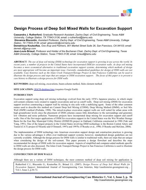
Design Process of Deep Soil Mixed Walls for Excavation Support
Design Process of Deep Soil Mixed Walls for Excavation Support
Design Process of Deep Soil Mixed Walls for Excavation Support

You also want an ePaper? Increase the reach of your titles
YUMPU automatically turns print PDFs into web optimized ePapers that Google loves.
<strong>Design</strong> <strong>Process</strong> <strong>of</strong> <strong>Deep</strong> <strong>Soil</strong> <strong>Mixed</strong> <strong>Walls</strong> <strong>for</strong> <strong>Excavation</strong> <strong>Support</strong><br />
Cassandra J. Ruther<strong>for</strong>d, Graduate Research Assistant, Zachry Dept. <strong>of</strong> Civil Engineering, Texas A&M<br />
University, College Station, TX 77843-3136; email: c-ruther<strong>for</strong>d@tamu.edu<br />
Giovanna Biscontin, Assistant Pr<strong>of</strong>essor, Zachry Dept. <strong>of</strong> Civil Engineering, Texas A&M University, College<br />
Station, TX 77843-3136; email: gbiscontin@civil.tamu.edu<br />
Demetrious Kouts<strong>of</strong>tas, Ove Arup and Partners, 901 Market Street Suite 26, San Francisco, CA 94103; email:<br />
demek.sf@arup.com<br />
Jean-Louis Briaud, Pr<strong>of</strong>essor and Holder <strong>of</strong> the Buchanan Chair, Zachry Dept. <strong>of</strong> Civil Engineering, Texas<br />
A&M University, College Station, Texas 77843-3136; email: briaud@tamu.edu<br />
ABSTRACT: The use <strong>of</strong> deep soil mixing (DSM) technology <strong>for</strong> excavation support is growing in use across the world. In<br />
recent years, a number <strong>of</strong> projects in the United States have incorporated DSM <strong>for</strong> excavation walls. As deep soil mixing<br />
becomes a more economical alternative to traditional excavation support systems, determining which methods <strong>of</strong> design<br />
are most appropriate will become an important issue. Currently, standardized guidelines <strong>for</strong> design <strong>of</strong> DSM walls are not<br />
available. Case histories such as the Islais Creek Transport/Storage Project in San Francisco Cali<strong>for</strong>nia can be used to<br />
illustrate the design process and steps that are unique to DSM excavation support. The focus <strong>of</strong> this paper is to present a<br />
case history to illustrate a design process <strong>for</strong> DSM walls.<br />
KEYWORDS: deep soil mixing, excavations, beam-column method, finite element method<br />
SITE LOCATION: IJGCH-database.kmz (requires Google Earth)<br />
INTRODUCTION<br />
<strong>Excavation</strong> support using deep soil mixing technology evolved from the early 1970’s Japanese practice, in which single<br />
soil-cement columns were created to support excavations and act as cut<strong>of</strong>f walls. <strong>Deep</strong> soil mixing (DSM) <strong>for</strong> excavation<br />
support involves constructing a support wall by mixing in situ soils with a stabilizing agent. Some <strong>of</strong> the other common<br />
names used to describe this method are Cement <strong>Deep</strong> <strong>Soil</strong> Mixing (CDSM), <strong>Deep</strong> Mixing Method (DMM), or <strong>Soil</strong> Mix<br />
Wall (SMW) method (Porbaha, 1998). The mixed-in-place excavation support walls are well suited <strong>for</strong> urban areas with<br />
high groundwater levels since the placement <strong>of</strong> DSM columns causes little disturbance to the surroundings and generates<br />
low vibration and noise pollution. Numerous projects have incorporated deep mixing <strong>for</strong> excavation support and cut<strong>of</strong>f<br />
walls. One <strong>of</strong> the first major applications <strong>of</strong> DSM <strong>for</strong> excavation support in the United States was the Wet Weather Storage<br />
Basin <strong>for</strong> the East Bay Municipal Utility District (EDMUD) project in Oakland, Cali<strong>for</strong>nia constructed in 1990 (Taki and<br />
Yang, 1991). One <strong>of</strong> the largest projects in the United States involving DSM technology is the Boston Central Artery and<br />
Tunnel (CA/T) project (O’Rourke and O’Donnell, 1997a and 1997b; O’Rourke et al., 1998, O’Rourke and McGinn, 2004).<br />
The implementation <strong>of</strong> DSM technology into American excavation support design and construction practices is growing<br />
due to the various advantages it <strong>of</strong>fers over traditional support systems; however, standardized design guidelines are not<br />
currently available. Although the design process <strong>for</strong> DSM walls is similar to traditional walls, there are steps that are unique<br />
when considering the design <strong>of</strong> the soil-cement. This paper presents a design flowchart and describes the steps<br />
recommended <strong>for</strong> design <strong>of</strong> DSM walls <strong>for</strong> excavation support. Aspects <strong>of</strong> simplified and computer-aided methods specific<br />
to DSM walls are also discussed. The Islais Creek Transport/Storage Project in San Francisco Cali<strong>for</strong>nia is used to illustrate<br />
the design process <strong>for</strong> DSM walls.<br />
CONSTRUCTION OF DSM WALLS<br />
Although there are a variety <strong>of</strong> DSM techniques, the most common method <strong>of</strong> deep soil mixing <strong>for</strong> application in<br />
Ruther<strong>for</strong>d C.J., Biscontin G., Kouts<strong>of</strong>tas D., Briaud J.L. (2007). <strong>Design</strong> <strong>Process</strong> <strong>of</strong> <strong>Deep</strong> <strong>Soil</strong> <strong>Mixed</strong> <strong>Walls</strong> <strong>for</strong><br />
<strong>Excavation</strong> <strong>Support</strong>. International Journal <strong>of</strong> Geoengineering Case histories, http://casehistories.geoengineer.org ,<br />
Vol.1, Issue 2, p.56-72.<br />
International Journal <strong>of</strong> Geoengineering Case Histories ©, Vol. 1, Issue 2, p. 56<br />
http://casehistories.geoengineer.org
excavations involves overlapping soil-cement columns that are either installed using a multi-auger rotary shaft or a drilling<br />
tool (Bruce et al., 1998). The construction requires specialized equipment <strong>for</strong> DSM and there<strong>for</strong>e contractors with<br />
specialized knowledge are recommended. The construction <strong>of</strong> DSM walls is typically faster than other traditional methods<br />
(structural diaphragm/slurry walls, sheet pile walls, soldier pile and lagging walls, secant/tangent pile wall and micro–pile<br />
walls) and generates fewer spoils than slurry (diaphragm) wall construction. Porbaha (1998) provides a comprehensive<br />
description <strong>of</strong> DSM construction and applications.<br />
A stabilizing agent is mixed with the soil by multiple mixing blades to <strong>for</strong>m the soil-cement wall. A variety <strong>of</strong> stabilizing<br />
agents can be used such as lime, fly ash, and cement; however, the most common is a slurry mixture <strong>of</strong> cement, water, and<br />
sometimes bentonite. The resulting deep mixed soil column is <strong>of</strong>ten referred to as soil-cement. Although the DSM<br />
specialty contractor <strong>of</strong>ten determines the mix design, it is important <strong>for</strong> the design engineer to understand factors<br />
contributing to the strength and permeability <strong>of</strong> the DSM column. The improved engineering properties <strong>of</strong> the stabilized<br />
soil are governed by a number <strong>of</strong> factors including soil type, slurry properties, mixing procedures and curing conditions<br />
(Yang, 2003). The unconfined compression strength <strong>of</strong> the soil-cement <strong>for</strong> an excavation support cut<strong>of</strong>f wall is usually<br />
greater than 700 kPa (100 psi) and hydraulic conductivity usually ranges from 10 -5 to 10 -6 cm/s (4 x 10 -6 to 4 x 10 -7 in/s)<br />
(Taki and Yang, 1991).<br />
Typically, steel rein<strong>for</strong>cement (usually wide flange H-beams or sheet piles) is placed in the soil-cement columns to resist<br />
bending. The typical arrangement <strong>of</strong> DSM excavation support walls is illustrated in Fig. 1. Steel rein<strong>for</strong>cement is installed<br />
in every other DSM column after mixing and the accessible face <strong>of</strong> each column is trimmed <strong>of</strong>f once the excavation is<br />
complete. The wall system is supported with at least one level <strong>of</strong> struts or anchors and walers <strong>for</strong> horizontal support. It is<br />
common <strong>for</strong> DSM excavation systems to have multiple levels <strong>of</strong> support.<br />
Quality assessment and per<strong>for</strong>mance monitoring procedures are recommended to meet specifications and ensure the<br />
continuity and homogeneity <strong>of</strong> the DSM wall. The experience and expertise <strong>of</strong> the project contractors play an important<br />
role in the quality <strong>of</strong> the resulting DSM walls (Porbaha, 2000).<br />
GENERAL DESIGN PROCESS FOR DSM WALLS<br />
Figure 1. Typical arrangement <strong>of</strong> DSM columns.<br />
The goal <strong>for</strong> DSM walls is to stabilize open cuts and to minimize wall movements by restraining earth pressures. Their<br />
main purpose is to act as a permanent support system maintaining the stability <strong>of</strong> the excavation against lateral earth<br />
pressures while controlling the de<strong>for</strong>mation and settlement <strong>of</strong> the surrounding structures (Porbaha, 2000). The design<br />
flowchart presented in Fig. 2 can be used to aid the engineer in the steps required <strong>for</strong> the design <strong>for</strong> DSM <strong>for</strong> excavation<br />
support (Ruther<strong>for</strong>d, 2004).<br />
The initial feasibility assessment (Step 1) <strong>of</strong> the application <strong>of</strong> DSM to a project is dependent on the site conditions and<br />
economics. Sites with ground settlement sensitivity, vibration sensitivity, high groundwater table, and/or s<strong>of</strong>t soils are <strong>of</strong>ten<br />
good candidates <strong>for</strong> the use <strong>of</strong> DSM. Once the feasibility <strong>of</strong> DSM is determined, the functional and design criteria <strong>for</strong> the<br />
International Journal <strong>of</strong> Geoengineering Case Histories ©, Vol. 1, Issue 2, p. 57<br />
http://casehistories.geoengineer.org
wall are established. The type <strong>of</strong> retaining wall system (Step 2) is decided based upon cost, site conditions, required wall<br />
height, speed <strong>of</strong> construction and other project specific requirements (Step 3).<br />
A seepage analysis (Step 4) using either chart methods or computer s<strong>of</strong>tware is carried out using initial wall geometry.<br />
Because DSM walls are <strong>of</strong>ten constructed in s<strong>of</strong>t soils, stability against heave action is a major problem during construction<br />
(Porbaha, 2000). An external stability analysis (Step 5) is per<strong>for</strong>med using classical methods such as method <strong>of</strong> slices,<br />
Bishop’s method, Janbu’s method and wedge method (Duncan and Wright, 2005).<br />
All the analysis and design <strong>of</strong> DSM walls is carried out on the repeatable wall section (Step 6). The repeatable wall section<br />
is the smallest length <strong>of</strong> the wall which repeats itself over and over to <strong>for</strong>m a complete wall. For DSM walls, the repeatable<br />
wall section is taken as the length <strong>of</strong> the wall between the midpoints on either side <strong>of</strong> a wide flange H-beam including the<br />
beam (Fig. 1). The vertical bearing capacity <strong>of</strong> the wall (Step 7) is determined by summing the <strong>for</strong>ces acting on the soilcement<br />
repeatable section. At the preliminary design stage, the length <strong>of</strong> wall over which the downdrag acts may be taken<br />
equal to the excavation height. More accurate analysis requires a computer aided analysis.<br />
The wall components design issues are dependent upon the specific construction details <strong>of</strong> the wall. The geometry <strong>of</strong> the<br />
wall including the embedment and the support system are determined. The wall design can be per<strong>for</strong>med using a variety <strong>of</strong><br />
techniques alone or in combination: (1) the pressure diagram and simplified methods, (2) the beam-column method, (3) and<br />
the finite element method (FEM). Because these methods were developed with different goals, each exhibits different<br />
advantages and disadvantages which will be discussed in further detail in the following sections.<br />
Simplified Methods <strong>for</strong> <strong>Design</strong> <strong>of</strong> DSM <strong>Walls</strong><br />
Many design guidelines recommend the use <strong>of</strong> the pressure diagram method <strong>for</strong> determining the loading on the wall<br />
components <strong>of</strong> excavation support systems (U.S. Department <strong>of</strong> the Navy, 1971; NAVFAC, 1982; U.S. Army Corps <strong>of</strong><br />
Engineers, 1989; AASHTO, 1990; FHWA, 1998, 1999). The pressure diagram method consists <strong>of</strong> assuming an empirical<br />
pressure diagram (Terzaghi and Peck, 1967) or a theoretical active-passive pressure diagram (Canadian Geotechnical<br />
Society, 1985; Cheney, 1988) acting on the wall. The earth pressure diagrams <strong>for</strong> the design <strong>of</strong> single support/tieback walls,<br />
such as DSM walls, have been a topic <strong>of</strong> much debate. Some recommend that a triangular earth pressure diagram (as with<br />
cantilever walls) be used <strong>for</strong> single row anchored walls. Weatherby (1998) and Mueller et al. (1998) recommend that the<br />
same apparent earth pressure diagrams used to design walls with multiple support/tiebacks be used to design single<br />
support/tieback walls. The pressures are distributed to the anchors and the wall embedment either by using the tributary<br />
area method (Terzaghi and Peck, 1967), the hinge method (Lambe and Wolfskill, 1970) or using equilibrium considerations<br />
(Canadian Geotechnical Society, 1985; Cheney, 1988).<br />
Once the wall pressures and support loads are estimated, the maximum bending moment is calculated at the point <strong>of</strong> zero<br />
shear and used to size the structural elements <strong>of</strong> the retaining system. Difficulties with the application <strong>of</strong> simplified<br />
methods arise due to the highly empirical nature <strong>of</strong> the design process and the assumptions required to simplify the soil<br />
stratigraphy and the structural system. Additionally, the pressure diagram method was not intended <strong>for</strong> the design <strong>of</strong> a stiff<br />
permanent wall and does not readily accommodate seepage analysis and unusual soil properties (Tamaro and Gould, 1992).<br />
A major limitation with the simplified methods is the lack <strong>of</strong> wall deflection and soil de<strong>for</strong>mation predictions. These are<br />
especially important in the design <strong>of</strong> DSM walls, which are typically installed in s<strong>of</strong>t soils where de<strong>for</strong>mation estimations<br />
are vital.<br />
The design <strong>of</strong> excavation support systems is evolving towards a deflection-based approach. Simplified methods have been<br />
developed, mostly based on case histories and parametric FEM analysis. Movements <strong>of</strong> in situ wall systems are related to<br />
the stiffness <strong>of</strong> the system. Briaud and Lim (1997, 1999) illustrate how anchor load magnitude directly influences<br />
deflection and bending moments <strong>of</strong> tieback walls. Using the proposed coefficient <strong>of</strong> apparent earth pressure (k) and<br />
relationships between k and the ratio <strong>of</strong> deflection at the top <strong>of</strong> the wall to the height <strong>of</strong> the excavation (u top /H) or ratio <strong>of</strong><br />
the mean deflection (u mean /H), the engineer can select the anchor lock–<strong>of</strong>f loads that will approximately generate a selected<br />
deflection (Fig. 3 and Fig. 4).<br />
Another method <strong>of</strong> de<strong>for</strong>mation control design is discussed by Clough and O’Rourke (1990). This semi-empirical method<br />
relates wall and soil mass de<strong>for</strong>mations to system stiffness and base stability. Contours <strong>of</strong> maximum lateral de<strong>for</strong>mation as<br />
a percentage <strong>of</strong> depth <strong>of</strong> excavation are represented in design charts <strong>for</strong> various soils. De<strong>for</strong>mations can be controlled<br />
within required limits by specifying design elements such as wall stiffness (EI), embedment depth <strong>of</strong> wall (D), and spacing<br />
International Journal <strong>of</strong> Geoengineering Case Histories ©, Vol. 1, Issue 2, p. 58<br />
http://casehistories.geoengineer.org
<strong>of</strong> horizontal supports (h). The system stiffness (S) is determined from the wall stiffness and the spacing <strong>of</strong> the horizontal<br />
supports (Fig. 5) as<br />
S =<br />
EI<br />
γ w<br />
h 4<br />
(1)<br />
where E is the modulus <strong>of</strong> elasticity <strong>of</strong> the wall material, I is the moment <strong>of</strong> inertia <strong>of</strong> a unit length <strong>of</strong> the wall, γ w is the unit<br />
weight <strong>of</strong> water, and h is the average spacing between supports. Calculations <strong>of</strong> the factor <strong>of</strong> safety against basal heave are<br />
used to determine an estimate <strong>for</strong> the maximum lateral deflection <strong>of</strong> the wall. Approximate pr<strong>of</strong>iles <strong>of</strong> lateral de<strong>for</strong>mations<br />
and settlement behind the wall can be determined following guidelines presented by Clough et al. (1989).<br />
Figure 2. DSM Wall <strong>Design</strong> Flowchart (After Ruther<strong>for</strong>d, 2004).<br />
International Journal <strong>of</strong> Geoengineering Case Histories ©, Vol. 1, Issue 2, p. 59<br />
http://casehistories.geoengineer.org
Figure 3. Earth Pressure Coefficients Vs. Mean Deflection (after Briaud and Lim, 1999).<br />
Figure 4. Earth Pressure Coefficients Vs. Top Deflection (after Briaud and Lim, 1999).<br />
International Journal <strong>of</strong> Geoengineering Case Histories ©, Vol. 1, Issue 2, p. 60<br />
http://casehistories.geoengineer.org
Figure 5. <strong>Design</strong> Curves to Obtain Maximum Lateral Wall Movement (or <strong>Soil</strong> Settlement) <strong>for</strong> S<strong>of</strong>t to Medium Clays (after<br />
Clough and O’Rourke, 1990).<br />
The Beam-Column Method <strong>for</strong> <strong>Design</strong> <strong>of</strong> DSM <strong>Walls</strong><br />
Computer-aided analysis is growing in use and represents the future trend in excavation support analysis and design. One<br />
advantage <strong>of</strong> computer-aided analysis over simplified methods is the availability <strong>of</strong> pr<strong>of</strong>iles <strong>of</strong> bending moments and<br />
deflection estimates. However, these methods require detailed knowledge <strong>of</strong> soil and wall properties and construction<br />
procedures.<br />
The beam-column method (Fig. 6) <strong>for</strong> tieback walls deals with the analysis <strong>of</strong> the wall as a structural element interacting<br />
with the soil and the anchors; it leads to sizing the wall and the anchors (Briaud and Kim, 1998). The beam-column method<br />
models the wall as a set <strong>of</strong> elements <strong>of</strong> length Δz, with bending stiffness (EI) and axial stiffness (AE). The soil is<br />
represented by a series <strong>of</strong> vertical and horizontal springs placed at the nodes between the elements.<br />
The springs are characterized by load-deflection or p-y curves. The equilibrium <strong>of</strong> a wall element under soil and support<br />
loads leads to the governing differential equations, which are solved by the finite difference technique. This method<br />
originates from the work <strong>of</strong> Winkler (1867) and Hetenyi (1946), but Matlock was one <strong>of</strong> the first to apply the general<br />
computer solution <strong>for</strong> the beam-column analysis to this reference (Matlock et al., 1981), while Halliburton (1968) first<br />
applied it to the flexible retaining wall problem. The beam-column method allows the estimation <strong>of</strong> a deflection pr<strong>of</strong>ile, a<br />
shear <strong>for</strong>ce pr<strong>of</strong>ile, a bending moment pr<strong>of</strong>ile and an axial-load pr<strong>of</strong>ile <strong>for</strong> the wall.<br />
In the analysis <strong>of</strong> DSM walls with the beam-column method, only the stiffness, EI, <strong>of</strong> the H-beam rein<strong>for</strong>cement is<br />
modeled, while the flexural stiffness added by the soil-cement is ignored. Based on laboratory testing, the bending stiffness<br />
(EI) <strong>of</strong> soil-cement columns is approximately 2 to 4% <strong>of</strong> the EI <strong>of</strong> the rein<strong>for</strong>cing beams (Wong et al., 1993). Ruther<strong>for</strong>d et<br />
al. (2005) illustrated that this assumption does not greatly affect the resulting bending moments and deflections. Wong et al.<br />
(1993) used the beam column method to predict the per<strong>for</strong>mance <strong>of</strong> a deep soil mixed wall in Texas.<br />
The Finite Element Method <strong>for</strong> <strong>Design</strong> <strong>of</strong> DSM <strong>Walls</strong><br />
International Journal <strong>of</strong> Geoengineering Case Histories ©, Vol. 1, Issue 2, p. 61<br />
http://casehistories.geoengineer.org
The finite element method, FEM allows great flexibility, but requires a number <strong>of</strong> input parameters including the material<br />
parameters <strong>for</strong> the wall (usually elastic), the anchors (elastic–plastic), and the soil (hyperbolic non-linear elastic or other),<br />
detailed boundary conditions and boundary loads (surcharge, buildings, etc.).<br />
Determination <strong>of</strong> boundary conditions <strong>for</strong> finite element models is one <strong>of</strong> the first steps in the numerical simulation (Fig. 7).<br />
In order to minimize the effect <strong>of</strong> the boundaries on the predicted ground movements, the mesh boundaries can be<br />
determined using Briaud and Lim (1997) recommendations. The width <strong>of</strong> the mesh is<br />
B e + W e (2)<br />
where B e = 3(H e + D), W e = 3D, H e is the height <strong>of</strong> the excavation and D is the depth from the bottom <strong>of</strong> the excavation to<br />
the hard layer.<br />
The simulated wall section or repeatable wall section must also be determined. Because the soil-cement is weak in tension<br />
its contribution to the stiffness <strong>of</strong> the wall is neglected; there<strong>for</strong>e the stiffness <strong>of</strong> the section is based solely on the stiffness<br />
<strong>of</strong> the wide flange beam.<br />
A drawback <strong>of</strong> using the finite element method is the number <strong>of</strong> soil parameters required <strong>for</strong> meaningful finite element<br />
models. Additionally, some finite element programs are difficult and time consuming to use. The use <strong>of</strong> the FEM is<br />
becoming simpler and simpler, but quality control <strong>of</strong> the results is critical.<br />
Figure 6. Beam-Column Method Schematic (after Briaud and Kim, 1998).<br />
International Journal <strong>of</strong> Geoengineering Case Histories ©, Vol. 1, Issue 2, p. 62<br />
http://casehistories.geoengineer.org
STRUCTURAL DESIGN<br />
Figure 7. Finite Element Method Schematic (after Briaud and Lim, 1997).<br />
The structural design (Step 8) <strong>of</strong> the components <strong>of</strong> DSM walls is the aspect in which DSM wall design most differs from<br />
traditional excavation support design. The approach <strong>for</strong> soil-cement walls most resembles that <strong>for</strong> soldier pile and lagging<br />
walls or secant walls. The design methodology includes steps to determine the rein<strong>for</strong>cement members to resist bending<br />
moment and shear stresses. The tensile strength <strong>of</strong> soil-cement is low; there<strong>for</strong>e designing soil-cement columns to resist<br />
bending stresses is not economical. The soil-cement between the rein<strong>for</strong>cement members is considered as lagging and is<br />
designed to resist and redistribute the horizontal stresses to the adjacent rein<strong>for</strong>cement (Taki and Yang, 1991). The stress<br />
analysis <strong>of</strong> the soil-cement between the rein<strong>for</strong>cement beams includes the evaluation <strong>of</strong> shear and bending moments in the<br />
horizontal plane and stresses inside the soil-cement mass as illustrated in Fig. 8.<br />
The steel rein<strong>for</strong>cement is designed to resist bending stresses in the vertical plane due to the lateral earth pressures<br />
transmitted by the soil-cement to the steel beams. The wide-flanges exhibit bending in the vertical plane while the soilcement,<br />
acting as lagging, bends in the horizontal plane. The most critical shear location is at the junction <strong>of</strong> the soil-cement<br />
and steel beam and requires calculations to check <strong>for</strong> bending failure and shear failure.<br />
Based on finite element studies by Taki and Yang (1991), an empirical design criterion was developed to avoid bending<br />
failure in the soil-cement. Bending failure is unlikely if<br />
L 2<br />
≤ D + h − 2e (3)<br />
where L 2 is the distance between the end <strong>of</strong> the wide flange beams, D is the diameter <strong>of</strong> the soil-cement column, h is the<br />
height <strong>of</strong> the wide flange beam, and e is the eccentricity defined as the distance between the center <strong>of</strong> the wide flange beam<br />
and the center <strong>of</strong> the soil-cement column after trimming.<br />
Shear failure is checked following recommendations by Pearlman and Himick (1993). The nominal shear strength <strong>of</strong> the<br />
soil-cement can be estimated similarly as that <strong>of</strong> concrete. Using the American Concrete Institute (ACI) equation, the shear<br />
resistance <strong>of</strong> the soil-cement block, V c (lbf) is defined as:<br />
V ( lb ) = λ2<br />
f ( psi)<br />
b ( in)<br />
d(<br />
in)<br />
′<br />
c f<br />
c<br />
w<br />
(4)<br />
where λ is estimated as 0.75 <strong>for</strong> lightweight concrete, f c ’ is the soil-cement shear strength in psi, b w is the width <strong>of</strong> the block<br />
in inches and d is the height <strong>of</strong> the block in inches. The shear resistance <strong>of</strong> the block, V c , must be greater than the shear<br />
<strong>for</strong>ce applied to the wall.<br />
International Journal <strong>of</strong> Geoengineering Case Histories ©, Vol. 1, Issue 2, p. 63<br />
http://casehistories.geoengineer.org
Figure 8. Structural Resistance <strong>of</strong> Wall Elements.<br />
CASE HISTORY<br />
The Islais Creek Transport/Storage Project in San Francisco, Cali<strong>for</strong>nia included the construction <strong>of</strong> approximately 500 m<br />
<strong>of</strong> box sewer along Army, Indiana and Tulare Streets. A portion <strong>of</strong> the box sewer also serves as a controlled overflow<br />
structure in the event that the storage capacity <strong>of</strong> the system is exceeded. Construction <strong>of</strong> the sewer and overflow structure<br />
required approximately 12-m deep excavations in relatively s<strong>of</strong>t soil with a high groundwater table. Key issues <strong>for</strong> the<br />
excavation were stability and de<strong>for</strong>mations particularly along the overflow structure where weak subsurface soils extended<br />
to depths <strong>of</strong> up to 33 m (Dames & Moore, 1997).<br />
A segment <strong>of</strong> the Army Street DSM wall will be used to illustrate the three wall component design methods. For the<br />
shoring system, deep soil mixing was selected to construct a diaphragm wall with wide flange beams spaced at 1.3 m. The<br />
soil cement columns were 0.91 m in diameter and wide flange beams (W30 x 108, EI = 304,565 kN·m2/m) were inserted<br />
1.3 m center-to-center. Three levels <strong>of</strong> internal struts were used to brace the excavation walls at 0.9 m, 4.9 m and 9.1 m.<br />
The excavation was 11 m wide and 11.7 m deep. The subsurface soil consisted <strong>of</strong> layers <strong>of</strong> fill to a depth <strong>of</strong> 5.5 m, a layer<br />
<strong>of</strong> dark gray, s<strong>of</strong>t to medium stiff, plastic clay, known locally as Bay Mud, to a depth <strong>of</strong> 14.0 m, Marine Sand to a depth <strong>of</strong><br />
15.8 m and Colluvium to a depth <strong>of</strong> 18.3 m. The soil layers are underlain by bedrock <strong>of</strong> the Franciscan Formation. The soil<br />
parameters used in the analysis are in Figure 9. Based on limited knowledge <strong>of</strong> the soil properties, conservative parameters<br />
were selected and only a drained analysis was conducted. An external stability analysis was per<strong>for</strong>med using Bishop’s<br />
method. Satisfactory external stability was determined. The seepage analysis in Plaxis showed limited flow and no piping<br />
or unstable conditions likely to develop.<br />
International Journal <strong>of</strong> Geoengineering Case Histories ©, Vol. 1, Issue 2, p. 64<br />
http://casehistories.geoengineer.org
Simplified Methods <strong>for</strong> <strong>Design</strong> <strong>of</strong> Case History<br />
Figure 9. Islais Creek Transport/Storage Project Assumed Section..<br />
Selecting a pressure diagram <strong>for</strong> the design is very difficult in the case <strong>of</strong> a multiple layer stratigraphy. Simplified pr<strong>of</strong>iles<br />
must be used to facilitate the calculations required in the simplified method. Since the least competent soil controls the<br />
lateral earth pressure, the Bay Mud was combined with other layers into one design soil unit.<br />
Two different earth pressure diagrams were constructed (Fig. 10). First, a trapezoid-shaped diagram with a maximum<br />
pressure <strong>of</strong> 51.25 kN/m 2 was calculated using an apparent earth pressure <strong>of</strong> (Weatherby, 1998):<br />
p AEP<br />
= 0.3γH (5)<br />
where p AEP is the apparent earth pressure, γ is the total unit weight <strong>of</strong> the soil and H is the height <strong>of</strong> the excavation. Using<br />
the tributary area method, the strut loads were determined as S 1 =95.8 kN, S 2 =288.1 kN and S 3 =196.4 kN.<br />
The second diagram follows suggestions by Weatherby (1998) <strong>for</strong> multiple strut walls. A maximum pressure <strong>of</strong> 45.97<br />
kN/m 2 was calculated using the “25H” trapezoid diagram. Using the tributary area method, the strut loads were determined<br />
as S 1 =79.29 kN, S 2 =189.14 kN and S 3 =147.46 kN.<br />
Once the pressure diagram and the anchor loads are known, the shear and bending moment diagrams can be drawn. The<br />
maximum moment <strong>for</strong> each diagram was calculated, as is typical in practice, at the depth <strong>of</strong> the first strut (3.14 kN·m and<br />
2.82 kN·m, respectively). Both <strong>of</strong> these moments can be safely resisted by the W30x108 wide flange beam, which was<br />
selected as rein<strong>for</strong>cement <strong>for</strong> the soil-cement columns. A major limitation <strong>of</strong> this design method is the lack <strong>of</strong> wall<br />
deflection predictions and the assumption that the maximum bending moment occurs at the first strut. The validity <strong>of</strong> this<br />
assumption will be discussed later.<br />
The lateral displacement <strong>of</strong> the wall can be predicted using the de<strong>for</strong>mation control method as described by Clough and<br />
O’Rourke (1990) and Briaud and Lim (1999). Based on the Briaud and Lim method (Fig. 3 and 4), the estimated mean<br />
deflection could range from 11.7 mm to 47.6 mm, and the estimated deflection at the top <strong>of</strong> the wall could range from 29<br />
mm to 46.8 mm using k equal to 0.3 and H equal to 11.7 m.<br />
Based on Clough and O’Rourke (1990), the shoring system stiffness (S) from Equation 1 was 128 given wall stiffness (EI)<br />
<strong>of</strong> 304,565 kN·m 2 /m (neglecting the soil-cement) and average vertical spacing between the strut supports (h) <strong>of</strong> 4.1 m. The<br />
factor <strong>of</strong> safety against basal heave was estimated using the s<strong>of</strong>tware program, XSTABLE, as 1.5. The estimated maximum<br />
horizontal movement <strong>of</strong> the system was 0.5% <strong>of</strong> the depth <strong>of</strong> the excavation, or 58 mm from Fig 5.<br />
International Journal <strong>of</strong> Geoengineering Case Histories ©, Vol. 1, Issue 2, p. 65<br />
http://casehistories.geoengineer.org
The Beam-Column Method <strong>for</strong> <strong>Design</strong> <strong>of</strong> Case History<br />
Figure 10. FEM and Beam-column Earth Pressures on Wall.<br />
The beam-column method requires the development <strong>of</strong> load-deflection curves, or p-y curves, to represent the soil layers and<br />
the supports. BMCOLM76 (Matlock et al. 1981) was used to implement the beam-column approach <strong>for</strong> the analysis <strong>of</strong> the<br />
DSM wall. The width (b) <strong>of</strong> the repeatable wall section was selected as the horizontal spacing between the vertical<br />
rein<strong>for</strong>cement (steel beams) or 1.3 m. The wall stiffness (EI) <strong>of</strong> the section was taken as 304,465 kN·m 2 /m or the stiffness<br />
<strong>of</strong> the rein<strong>for</strong>cing beam only, ignoring the contribution <strong>of</strong> the soil-cement. The strut loads were determined using the<br />
tributary area method from the apparent (0.3 γ H) earth pressure diagram as S 1 =95.8 kN, S 2 =288.1 kN and S 3 =196.4 kN. P-<br />
y curves were determined <strong>for</strong> multiple points in each layer using the soil reactions and the deflections <strong>of</strong> the wall in passive<br />
and active resistance following recommendations <strong>of</strong> Briaud and Kim (1999) (Fig. 11). Table 1 provides the earth pressure<br />
coefficients and deflections used <strong>for</strong> each soil layer. In the zone where the wall had both sides in contact with soil (below<br />
excavation level), the p-y curves were constructed according to Briaud (1992). Fig. 10 compares the pressure diagram from<br />
the beam-column method with the diagrams used in the simplified method. <strong>Soil</strong> reactions in the vertical direction were<br />
neglected <strong>for</strong> this study. Additionally, the construction sequence was not simulated.<br />
Table 1. Earth Pressure Coefficients and Displacements<br />
<strong>Soil</strong> Type<br />
(1)<br />
Range <strong>of</strong> Depth (m)<br />
(2)<br />
K a<br />
(3)<br />
K p<br />
(4)<br />
y a (mm)<br />
(5)<br />
y p (mm)<br />
(6)<br />
Fill 0 - 5.5 0.27 3.70 1.27 12.7<br />
Bay Mud 5.5 – 14.0 0.28 3.54 25 5.1<br />
Marine Sand 14.0 – 15.8 0.25 4.00 1.27 12.7<br />
Colluvium 15.8 – 18.3 0.22 4.60 1.27 12.7<br />
International Journal <strong>of</strong> Geoengineering Case Histories ©, Vol. 1, Issue 2, p. 66<br />
http://casehistories.geoengineer.org
Figure 11. P-y curves (a) located at 5.5 m depth in Fill (b) located at 8.4 m in Bay Mud (c) located at 15.8 m in Marine<br />
Sand (d) located at 18.3 m in Colluvium.<br />
The Finite Element Method <strong>for</strong> <strong>Design</strong> <strong>of</strong> Case History<br />
A number <strong>of</strong> finite element method programs are available. Plaxis (Brinkgreve and Vermeer, 1998) was used to model the<br />
DSM wall case history. The Mohr-Coulomb elastic-plastic model was used to simulate the response <strong>of</strong> the soils. The choice<br />
was mandated by the lack <strong>of</strong> in<strong>for</strong>mation on the soil properties beyond strength. Additional soil parameter assumptions<br />
were based on reported properties at nearby locations. Due to symmetry, only half <strong>of</strong> the excavation was analyzed in the<br />
simulation. The width <strong>of</strong> the mesh was 95.5 m and the height was 22.0 m based on recommendations by Briaud and Lim<br />
(1997). The finite elements mesh consisted <strong>of</strong> plane strain, 15-node elements and was generated at a very fine global<br />
coarseness, additionally refined around the wall. <strong>Soil</strong> parameters are given in Fig. 9.<br />
The construction sequence was simulated using several phases. The initial conditions were assigned based on a phreatic<br />
ground water level at 8.4 m. The pore water pressures were generated assuming hydrostatic conditions and then the initial<br />
stresses were calculated using the Plaxis K 0 -procedure. The strut loads were estimated as previously discussed in the beamcolumn<br />
method section. First, the wall was installed to the desired depth (18.3 m), the soil was excavated to 1.83 m, the<br />
first level <strong>of</strong> struts was installed at 0.91 m, and pre-stressed to 95.8 kN or 73.67 kN/m (Phase 1). Phase 2 consisted <strong>of</strong><br />
additional excavation to 6.71 m and installation <strong>of</strong> the second level <strong>of</strong> struts at 4.88 m, pre-stressed to 288.1 kN or 221.6<br />
kN/m. Phase 3 required a third excavation to a depth <strong>of</strong> 11.7 m and installation <strong>of</strong> the final level <strong>of</strong> struts at 9.1 m pre-<br />
International Journal <strong>of</strong> Geoengineering Case Histories ©, Vol. 1, Issue 2, p. 67<br />
http://casehistories.geoengineer.org
stressed to 196.4 kN or 151.1 kN/m. Since this phase consists <strong>of</strong> excavating to a depth below the ground water, de-watering<br />
<strong>of</strong> the excavation was undertaken. To reflect this condition, the phreatic water level in the FEM was drawn down. The finite<br />
element simulations provide bending moment estimates and predictions <strong>of</strong> wall deflection and soil de<strong>for</strong>mation (Fig. 12 and<br />
13). More detail <strong>of</strong> the simulations is provided by Ruther<strong>for</strong>d (2004).<br />
Figure 12. Horizontal Wall De<strong>for</strong>mation Comparison.<br />
Figure 13. Bending Moment Comparison.<br />
International Journal <strong>of</strong> Geoengineering Case Histories ©, Vol. 1, Issue 2, p. 68<br />
http://casehistories.geoengineer.org
Structural <strong>Design</strong> <strong>of</strong> Case History<br />
The structural design <strong>of</strong> the DSM wall is per<strong>for</strong>med following methods recommended by Taki and Yang (1990) and<br />
Pearlman and Himick (1993), as described in previous section. Fig. 14 illustrates the calculations required <strong>for</strong> bending<br />
failure check and Fig. 15 illustrates the calculations required to check <strong>for</strong> shear failure. Because the distance between the<br />
rein<strong>for</strong>cement was less than the sum <strong>of</strong> the diameter <strong>of</strong> the soil-cement and the height <strong>of</strong> the rein<strong>for</strong>cement, the soil-cement<br />
will not fail in bending. Shear failure was checked by ensuring that the shear resistance <strong>of</strong> the soil-cement is greater than<br />
the shear transmitted to the wall by earth pressures. There<strong>for</strong>e, the H-section is not overstressed.<br />
Figure 14. Bending Failure Calculations.<br />
Figure 15. Shear Failure Calculations.<br />
International Journal <strong>of</strong> Geoengineering Case Histories ©, Vol. 1, Issue 2, p. 69<br />
http://casehistories.geoengineer.org
DISCUSSION<br />
Fig. 12 shows the measured wall deflections <strong>for</strong> the case history compared with estimated deflections from the simplified<br />
methods, beam column method, and finite element method. The de<strong>for</strong>mation based methods predicted a maximum lateral<br />
de<strong>for</strong>mation <strong>of</strong> 58 mm (Clough and O’Rourke, 1990) and a range <strong>of</strong> 11.7 mm to 47.6 mm (Briaud and Lim, 1999). All<br />
three methods compare favorably to the measured de<strong>for</strong>mations that ranged between 38 and 56 mm <strong>for</strong> the wall segment.<br />
The finite element and beam-column predictions tend to overestimate the maximum deflection; this may be due to the<br />
conservative assumptions <strong>for</strong> the soil parameters based on the limited knowledge <strong>of</strong> the soil properties. The negative<br />
deflection at the top <strong>of</strong> the wall predicted by the finite element and beam-column methods are likely due to the fact that no<br />
hysteresis is considered in the simulation, but occurs due to soil plasticity in reality. The actual strut loads <strong>for</strong> the site were<br />
unavailable; there<strong>for</strong>e, the loads were taken as those calculated using the tributary area method.<br />
The differences between the methods are additionally illustrated by comparing the bending moment pr<strong>of</strong>iles (Fig. 13).<br />
Using the simplified method, the design maximum bending moment is calculated at the top strut. Although the bending<br />
moment magnitude at this location calculated by the simplified method is relatively close to those predicted by the finite<br />
element and beam-column method, the bending moment prediction by the simplified method is much smaller than the<br />
maximum bending moment which occurs much farther along the wall at a location closer to the excavation depth. The finite<br />
element and beam-column methods provide bending moment pr<strong>of</strong>iles along the length <strong>of</strong> the wall. Both methods provide<br />
similar shaped bending moment curves and maximum values, although the finite element method estimates a larger<br />
moment at each strut.<br />
The FEM method has the ability to simulate multiple phases <strong>of</strong> construction easily whereas to do so using the beam-column<br />
method is quite time consuming. Briaud and Kim (1998) show how to simulate the construction sequence with the beamcolumn<br />
method and indicate that it makes little difference in predicted bending moment pr<strong>of</strong>iles compared to a one step<br />
excavation; however, it does provide deflections which are closer to the measured deflections. The actual bending<br />
moments <strong>for</strong> the site were unavailable.<br />
Pressure diagrams are very simple but use restricting and <strong>of</strong>ten unrealistic assumptions; additionally, they do not lead to<br />
deflection predictions. This limits the effectiveness <strong>of</strong> these methods <strong>for</strong> DSM wall design. The beam-column method is <strong>of</strong><br />
intermediate complexity, theoretically sound, and includes deflection and bending moment pr<strong>of</strong>ile predictions. However, it<br />
cannot predict settlement behind the wall. The finite element method is more complicated and requires extensive<br />
knowledge <strong>of</strong> the soil as well as the construction technique; however, it provides the most realistic de<strong>for</strong>mation, deflection<br />
and bending moment predictions.<br />
The design <strong>of</strong> the overall system <strong>for</strong> DSM walls is similar to traditional excavation support systems; however, the design <strong>of</strong><br />
the wall components is unique to DSM walls. Ensuring safety against failure in bending and shear in the soil-cement is an<br />
important addition to the design <strong>of</strong> the structural resistance <strong>of</strong> the wall system. This additional step is carried out through a<br />
simplified method since most 2-D numerical tools cannot handle composite cross sections.<br />
CONCLUSION<br />
DSM walls are used more and more because <strong>of</strong> the advantages they provide over traditional excavation support. This paper<br />
presented a design process providing more standardized procedures including alternatives suitable <strong>for</strong> simplified<br />
calculations and computer-aided analysis. The design flowchart was illustrated through a case history and the results <strong>of</strong><br />
various methods were compared.<br />
The simplified method is easier to use, but can only be applied to much simplified soil stratigraphies. However, the<br />
limitations associated with deflection and bending moment estimates suggest that this method should only be used as a<br />
preliminary tool <strong>for</strong> the design <strong>of</strong> DSM walls. The beam-column method provides both wall deflection predictions and<br />
bending moment estimates; however, one must keep in mind the limitations associated with soil movement predictions.<br />
Finite element simulations allow <strong>for</strong> more realistic ground de<strong>for</strong>mation and wall deflection predictions <strong>for</strong> DSM supported<br />
excavations. FEM also allows simulation <strong>of</strong> different phases <strong>of</strong> the construction sequence permitting direct evaluation <strong>of</strong><br />
the displacement at each stage <strong>of</strong> construction. These are advantageous <strong>for</strong> DSM walls, which are <strong>of</strong>ten installed in s<strong>of</strong>t<br />
soils where reliable ground de<strong>for</strong>mation predictions are needed.<br />
International Journal <strong>of</strong> Geoengineering Case Histories ©, Vol. 1, Issue 2, p. 70<br />
http://casehistories.geoengineer.org
Future developments should include more detailed analysis <strong>of</strong> soil-cement acting as lagging and its contribution to resist<br />
bending. Currently, DSM design does not account <strong>for</strong> any contribution <strong>of</strong> the soil-cement to the bending stiffness <strong>of</strong> the<br />
wall.<br />
ACKNOWLEDGEMENTS<br />
This paper is the partial result <strong>of</strong> a research project sponsored by the National <strong>Deep</strong> Mixing (NDM) pooled fund program<br />
and the Federal Highway Administration (FHWA). Mr. Al DiMillio was the technical contact <strong>for</strong> FHWA. Dr. Ali Porbaha<br />
was the technical director <strong>of</strong> the advisory group. The authors thank their board <strong>of</strong> consultants namely Mr. George Tamaro<br />
<strong>of</strong> Mueser Rutledge Consulting Engineers, Mr. Demetrious Kouts<strong>of</strong>tas <strong>of</strong> Ove Arup and Partners, Dr. Tom O'Rourke <strong>of</strong><br />
Cornell University and Mr. Dave Weatherby <strong>of</strong> Schnabel Foundations <strong>for</strong> their valuable contributions towards this project.<br />
REFERENCES<br />
American Association <strong>of</strong> State Highway and Transportation Officials (AASHTO). (1990). Specification <strong>for</strong> Permanent<br />
Ground Anchors; AASHTO–AGC–ARTBA Joint Committee Task Force 27 Report, Washington D.C.<br />
Briaud, J.-L. (1992). The Pressuremeter, Taylor & Francis, London, UK.<br />
Briaud, J.–L., and Kim, B.K. (1998). Beam Column Method <strong>for</strong> Tieback <strong>Walls</strong>, Journal <strong>of</strong> Geotechnical and<br />
Geoenvironmental Engineering, 124(1), 67–79.<br />
Briaud, J.–L., and Lim, Y. (1997). <strong>Soil</strong> Nailed Wall Under Piled Bridge Abutment: Simulation and Guidelines, Journal <strong>of</strong><br />
Geotechnical and Geoenvironmental Engineering, 123(11), 1043–1050.<br />
Briaud, J.–L., and Lim, Y. (1999). Tieback <strong>Walls</strong> in Sand: Numerical Simulation and <strong>Design</strong> Implications, Journal <strong>of</strong><br />
Geotechnical and Geoenvironmental Engineering, 125(2), 101–111.<br />
Brinkgreve R.B.J. and Vermeer P.A. (1998). Finite Element Code <strong>for</strong> <strong>Soil</strong> and Rock Analysis. PLAXIS 7.0 manual.<br />
Balkema.<br />
Bruce, D. A., Bruce, M. E. C., and A. DiMileo (1998). <strong>Deep</strong> Mixing Method: A Global Perspective, Geotechnical Special<br />
Publication No. 81, A. Maher and D. S. Yang, Eds., ASCE, Reston, VA, 1-15.<br />
Canadian foundation engineering manual (CFEM). (1985). Canadian Geotechnical Society, BiTech Publishers, Vancouver,<br />
B.C., Canada.<br />
Cheney, R.S. (1988). Permanent Ground Anchors. Report. No. FWHA-DP-68-1R, Federal Highway Administration,<br />
Washington, D.C.<br />
Clough, G.W., and O’Rourke, T.D. (1990). Construction Induced Movements <strong>of</strong> In-Situ <strong>Walls</strong>, ASCE, Geotechnical<br />
Special Publication No. 25 – <strong>Design</strong> and Per<strong>for</strong>mance <strong>of</strong> Earth Retaining Structures, 439-470.<br />
Clough, G.W., Smith, E.M and Sweeney, B.P. (1989). Movement Control <strong>of</strong> <strong>Excavation</strong> <strong>Support</strong> Systems by Iterative<br />
<strong>Design</strong>, Proceeding, ASCE, Foundation Engineering Congress: Current Principles and Practices, Vol. 2, 869-884.<br />
Dames & Moore (1997). Draft report results <strong>of</strong> the construction monitoring program: Islais Creek Transport/Storage<br />
project: Contract D, Volume I: Main report, San Francisco, CA.<br />
Duncan, J.M. and Wright, S.G. (2005). <strong>Soil</strong> Strength and Slope Stability. John Wiley & Sons, New York, NY.<br />
Federal Highway Administration (FHWA). (1998) <strong>Design</strong> Manual <strong>for</strong> Permanent Ground Anchor <strong>Walls</strong>, FHWA–RD–97–<br />
130, Federal Highway Administration, Washington, D.C.<br />
Federal Highway Administration (FHWA). (1999) Ground Anchors and Anchored Systems. FHWA–IF–99–015, Federal<br />
Highway Administration, Washington, D.C.<br />
Halliburton, T.A. (1968). Numerical Analysis <strong>of</strong> Flexible Retaining Structures. Proceeding ,ASCE, 94 (6), 1233-1251.<br />
Hetenyi, M. (1946). Beams on Elastic Foundations. University <strong>of</strong> Michigan Press, Ann Arbor, Mich.<br />
Kouts<strong>of</strong>tas, D.C. (1999). <strong>Excavation</strong> in San Francisco Bay Mud: <strong>Design</strong> <strong>for</strong> De<strong>for</strong>mation Control. Geo-Engineering <strong>for</strong><br />
Underground Facilities Proceeding. <strong>of</strong> the Conference <strong>of</strong> American Society <strong>of</strong> Civil Engineers, University <strong>of</strong> Illinois,<br />
337-392.<br />
Lambe, T.W. and Wolfskill, A.L. (1970). Measured Per<strong>for</strong>mance <strong>of</strong> Braced <strong>Excavation</strong>. Journal <strong>Soil</strong> Mechanics and<br />
Foundation Division, ASCE, 95(6), 817-836.<br />
Matlock, H., Bogard, D., and Lam, I. (1981). BMCOL76: A Computer Program <strong>for</strong> the Analysis <strong>of</strong> Beam-columns under<br />
Static Axial and Lateral Loading. Program developed at the University <strong>of</strong> Texas at Austin, under grant from Fugro,<br />
Inc., and documented at Ertec, Inc., Long Beach, CA.<br />
Mueller, C.G., Long, L.H., Weatherby, D.E., Cording, E.J., Powers III, W.F., and Briaud, J.-L. (1998). Summary Report <strong>of</strong><br />
Research on Permanent Ground Anchor <strong>Walls</strong>, Volume III: Model-scale Wall Tests and Ground Anchor Tests, Report<br />
No. FHWA-RD-98-067, Federal Highway Administration, McLean, VA.<br />
International Journal <strong>of</strong> Geoengineering Case Histories ©, Vol. 1, Issue 2, p. 71<br />
http://casehistories.geoengineer.org
Naval Facilities (NAVFAC). (1982). Foundation and Earth Structures: Naval Facilities Engineering Command <strong>Design</strong><br />
Manual, NAVFAC DM–7.2, U.S. Department <strong>of</strong> the Navy, Alexandria, VA.<br />
O’Rourke, T.D. and McGinn, A.J. (2004). Case History <strong>of</strong> <strong>Deep</strong> Mixing <strong>Soil</strong> Stabilization <strong>for</strong> Boston Central Artery.<br />
Geotechnical Engineering <strong>for</strong> Transportation Projects, 1, 77-128.<br />
O’Rourke, T.D. and O’Donnell, C.J. (1997a). <strong>Deep</strong> Rotational Stability <strong>of</strong> Tiedback <strong>Excavation</strong>s in Clay. Journal <strong>of</strong><br />
Geotechnical Engineering, 123(6), 506–515.<br />
O’Rourke, T. D and O’Donnell, C.J. (1997b). Field Behavior <strong>of</strong> <strong>Excavation</strong> Stabilized by <strong>Deep</strong> <strong>Soil</strong> Mixing. Journal <strong>of</strong><br />
Geotechnical and Geoenvironmental Engineering, 123(6), 516–524.<br />
O’Rourke, T.D., McGinn, A.J., and Dewsnap (1998). Case History <strong>of</strong> <strong>Excavation</strong> Stabilized by <strong>Deep</strong> Mixing Methods,<br />
<strong>Design</strong> and Construction <strong>of</strong> Earth Retaining Systems, ASCE, Reston, VA, 41-61.<br />
Pearlman, S.L. and Himick, D.E (1993). Anchored <strong>Excavation</strong> <strong>Support</strong> Using SMW. <strong>Deep</strong> Foundation Institute, 18th<br />
Annual Conference, Pittsburgh, PA, 101-120.<br />
Porbaha, A. (1998). State <strong>of</strong> the Art in <strong>Deep</strong> Mixing Technology: Basic Concepts. Ground Improvement, 2(2), 81–92.<br />
Porbaha, A. (2000). State <strong>of</strong> the Art in <strong>Deep</strong> Mixing Technology. Part IV: <strong>Design</strong> Considerations. Ground Improvement,<br />
4(3), 111–125.<br />
Ruther<strong>for</strong>d, C. J., (2004). <strong>Design</strong> Manual <strong>for</strong> <strong>Excavation</strong> <strong>Support</strong> Using <strong>Deep</strong> <strong>Soil</strong> Mixing, Master <strong>of</strong> Science thesis, Texas<br />
A&M University, College Station, Texas.<br />
Ruther<strong>for</strong>d, C.J., Biscontin, G. and Briaud, J.-L. (2005). De<strong>for</strong>mation Predictions Based on Estimates <strong>of</strong> <strong>Soil</strong> Cement<br />
Modulus and Flexural Stiffness, Proceedings, The 11th International Conference <strong>of</strong> IACMAG, June 19-24, 2005,<br />
Turin, Italy, Vol. 3, 433-440.<br />
Taki, O. and Yang, D.S. (1991). <strong>Soil</strong>–Cement <strong>Mixed</strong> Wall Technique. ASCE Special Conference, Denver, CO, 298–309.<br />
Tamaro, G. J. and Gould, J.P. (1992). Analysis and <strong>Design</strong> <strong>of</strong> Cast In Situ <strong>Walls</strong> (Diaphragm <strong>Walls</strong>). Retaining Structures.<br />
Thomas Tel<strong>for</strong>d, London, 343-352.<br />
Terzaghi, K. and Peck, R.B. (1967). <strong>Soil</strong> Mechanics in Engineering Practice, Second Edition. John Wiley & Sons, New<br />
York City, NY.<br />
U.S. Army Corps <strong>of</strong> Engineers. (1989). Engineering and <strong>Design</strong>: Retaining and Flood <strong>Walls</strong>, EM 1110-2-2502, U.S. Army<br />
Corps <strong>of</strong> Engineers, Washington, D.C.<br />
U.S. Department <strong>of</strong> the Navy. (1971). <strong>Design</strong> Manual – <strong>Soil</strong> Mechanics, Foundations, and Earth Structures, NAVFAC DM-<br />
7, Washington, D.C.<br />
Weatherby, D. (1998). <strong>Design</strong> Manual <strong>for</strong> Permanent Ground Anchor <strong>Walls</strong>, FWHA report no. FHWA-RD-97-130,<br />
Federal Highway Administration, Washington, D.C.<br />
Winkler, E. (1867). Die Lehre von Elastizitat und Festigkeit. H. Dominicus, Prague, Czechoslovakia.<br />
Wong, D.O., Stephen, A.J., Williams, C.E., and Rippley, R.L. (1993). Predicted and Observed Behavior <strong>of</strong> a <strong>Deep</strong>-<strong>Soil</strong>-<br />
Mixing Braced Wall. Transportation Research Record, 1406, 41-49.<br />
Yang, D.S. (2003). <strong>Soil</strong>–Cement <strong>Walls</strong> <strong>for</strong> <strong>Excavation</strong> <strong>Support</strong>. Earth Retention Systems 2003: A Joint Conference<br />
presented by ASCE Metropolitan Section <strong>of</strong> Geotechnical Group, The <strong>Deep</strong> Foundations Institute, and The<br />
International Association <strong>of</strong> Foundation Drilling, New York City, NY.<br />
International Journal <strong>of</strong> Geoengineering Case Histories ©, Vol. 1, Issue 2, p. 72<br />
http://casehistories.geoengineer.org
The International Journal <strong>of</strong> Geoengineering Case Histories<br />
(IJGCH) is funded by:<br />
Email us at journal@geoengineer.org if your company wishes to fund the International Journal <strong>of</strong> Geoengineering<br />
Case Histories.