Design Process of Deep Soil Mixed Walls for Excavation Support
Design Process of Deep Soil Mixed Walls for Excavation Support
Design Process of Deep Soil Mixed Walls for Excavation Support

You also want an ePaper? Increase the reach of your titles
YUMPU automatically turns print PDFs into web optimized ePapers that Google loves.
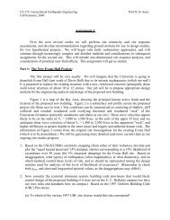
STRUCTURAL DESIGN<br />
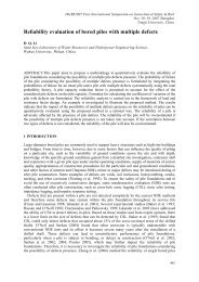
Figure 7. Finite Element Method Schematic (after Briaud and Lim, 1997).<br />
The structural design (Step 8) <strong>of</strong> the components <strong>of</strong> DSM walls is the aspect in which DSM wall design most differs from<br />
traditional excavation support design. The approach <strong>for</strong> soil-cement walls most resembles that <strong>for</strong> soldier pile and lagging<br />
walls or secant walls. The design methodology includes steps to determine the rein<strong>for</strong>cement members to resist bending<br />
moment and shear stresses. The tensile strength <strong>of</strong> soil-cement is low; there<strong>for</strong>e designing soil-cement columns to resist<br />
bending stresses is not economical. The soil-cement between the rein<strong>for</strong>cement members is considered as lagging and is<br />
designed to resist and redistribute the horizontal stresses to the adjacent rein<strong>for</strong>cement (Taki and Yang, 1991). The stress<br />
analysis <strong>of</strong> the soil-cement between the rein<strong>for</strong>cement beams includes the evaluation <strong>of</strong> shear and bending moments in the<br />
horizontal plane and stresses inside the soil-cement mass as illustrated in Fig. 8.<br />
The steel rein<strong>for</strong>cement is designed to resist bending stresses in the vertical plane due to the lateral earth pressures<br />
transmitted by the soil-cement to the steel beams. The wide-flanges exhibit bending in the vertical plane while the soilcement,<br />
acting as lagging, bends in the horizontal plane. The most critical shear location is at the junction <strong>of</strong> the soil-cement<br />
and steel beam and requires calculations to check <strong>for</strong> bending failure and shear failure.<br />
Based on finite element studies by Taki and Yang (1991), an empirical design criterion was developed to avoid bending<br />
failure in the soil-cement. Bending failure is unlikely if<br />
L 2<br />
≤ D + h − 2e (3)<br />
where L 2 is the distance between the end <strong>of</strong> the wide flange beams, D is the diameter <strong>of</strong> the soil-cement column, h is the<br />
height <strong>of</strong> the wide flange beam, and e is the eccentricity defined as the distance between the center <strong>of</strong> the wide flange beam<br />
and the center <strong>of</strong> the soil-cement column after trimming.<br />
Shear failure is checked following recommendations by Pearlman and Himick (1993). The nominal shear strength <strong>of</strong> the<br />
soil-cement can be estimated similarly as that <strong>of</strong> concrete. Using the American Concrete Institute (ACI) equation, the shear<br />
resistance <strong>of</strong> the soil-cement block, V c (lbf) is defined as:<br />
V ( lb ) = λ2<br />
f ( psi)<br />
b ( in)<br />
d(<br />
in)<br />
′<br />
c f<br />
c<br />
w<br />
(4)<br />
where λ is estimated as 0.75 <strong>for</strong> lightweight concrete, f c ’ is the soil-cement shear strength in psi, b w is the width <strong>of</strong> the block<br />
in inches and d is the height <strong>of</strong> the block in inches. The shear resistance <strong>of</strong> the block, V c , must be greater than the shear<br />
<strong>for</strong>ce applied to the wall.<br />
International Journal <strong>of</strong> Geoengineering Case Histories ©, Vol. 1, Issue 2, p. 63<br />
http://casehistories.geoengineer.org