Design Process of Deep Soil Mixed Walls for Excavation Support
Design Process of Deep Soil Mixed Walls for Excavation Support
Design Process of Deep Soil Mixed Walls for Excavation Support

You also want an ePaper? Increase the reach of your titles
YUMPU automatically turns print PDFs into web optimized ePapers that Google loves.
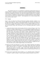
Figure 11. P-y curves (a) located at 5.5 m depth in Fill (b) located at 8.4 m in Bay Mud (c) located at 15.8 m in Marine<br />
Sand (d) located at 18.3 m in Colluvium.<br />
The Finite Element Method <strong>for</strong> <strong>Design</strong> <strong>of</strong> Case History<br />
A number <strong>of</strong> finite element method programs are available. Plaxis (Brinkgreve and Vermeer, 1998) was used to model the<br />
DSM wall case history. The Mohr-Coulomb elastic-plastic model was used to simulate the response <strong>of</strong> the soils. The choice<br />
was mandated by the lack <strong>of</strong> in<strong>for</strong>mation on the soil properties beyond strength. Additional soil parameter assumptions<br />
were based on reported properties at nearby locations. Due to symmetry, only half <strong>of</strong> the excavation was analyzed in the<br />
simulation. The width <strong>of</strong> the mesh was 95.5 m and the height was 22.0 m based on recommendations by Briaud and Lim<br />
(1997). The finite elements mesh consisted <strong>of</strong> plane strain, 15-node elements and was generated at a very fine global<br />
coarseness, additionally refined around the wall. <strong>Soil</strong> parameters are given in Fig. 9.<br />
The construction sequence was simulated using several phases. The initial conditions were assigned based on a phreatic<br />
ground water level at 8.4 m. The pore water pressures were generated assuming hydrostatic conditions and then the initial<br />
stresses were calculated using the Plaxis K 0 -procedure. The strut loads were estimated as previously discussed in the beamcolumn<br />
method section. First, the wall was installed to the desired depth (18.3 m), the soil was excavated to 1.83 m, the<br />
first level <strong>of</strong> struts was installed at 0.91 m, and pre-stressed to 95.8 kN or 73.67 kN/m (Phase 1). Phase 2 consisted <strong>of</strong><br />
additional excavation to 6.71 m and installation <strong>of</strong> the second level <strong>of</strong> struts at 4.88 m, pre-stressed to 288.1 kN or 221.6<br />
kN/m. Phase 3 required a third excavation to a depth <strong>of</strong> 11.7 m and installation <strong>of</strong> the final level <strong>of</strong> struts at 9.1 m pre-<br />
International Journal <strong>of</strong> Geoengineering Case Histories ©, Vol. 1, Issue 2, p. 67<br />
http://casehistories.geoengineer.org