Design Process of Deep Soil Mixed Walls for Excavation Support
Design Process of Deep Soil Mixed Walls for Excavation Support
Design Process of Deep Soil Mixed Walls for Excavation Support

Create successful ePaper yourself
Turn your PDF publications into a flip-book with our unique Google optimized e-Paper software.
excavations involves overlapping soil-cement columns that are either installed using a multi-auger rotary shaft or a drilling<br />
tool (Bruce et al., 1998). The construction requires specialized equipment <strong>for</strong> DSM and there<strong>for</strong>e contractors with<br />
specialized knowledge are recommended. The construction <strong>of</strong> DSM walls is typically faster than other traditional methods<br />
(structural diaphragm/slurry walls, sheet pile walls, soldier pile and lagging walls, secant/tangent pile wall and micro–pile<br />
walls) and generates fewer spoils than slurry (diaphragm) wall construction. Porbaha (1998) provides a comprehensive<br />
description <strong>of</strong> DSM construction and applications.<br />
A stabilizing agent is mixed with the soil by multiple mixing blades to <strong>for</strong>m the soil-cement wall. A variety <strong>of</strong> stabilizing<br />
agents can be used such as lime, fly ash, and cement; however, the most common is a slurry mixture <strong>of</strong> cement, water, and<br />
sometimes bentonite. The resulting deep mixed soil column is <strong>of</strong>ten referred to as soil-cement. Although the DSM<br />
specialty contractor <strong>of</strong>ten determines the mix design, it is important <strong>for</strong> the design engineer to understand factors<br />
contributing to the strength and permeability <strong>of</strong> the DSM column. The improved engineering properties <strong>of</strong> the stabilized<br />
soil are governed by a number <strong>of</strong> factors including soil type, slurry properties, mixing procedures and curing conditions<br />
(Yang, 2003). The unconfined compression strength <strong>of</strong> the soil-cement <strong>for</strong> an excavation support cut<strong>of</strong>f wall is usually<br />
greater than 700 kPa (100 psi) and hydraulic conductivity usually ranges from 10 -5 to 10 -6 cm/s (4 x 10 -6 to 4 x 10 -7 in/s)<br />
(Taki and Yang, 1991).<br />
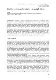
Typically, steel rein<strong>for</strong>cement (usually wide flange H-beams or sheet piles) is placed in the soil-cement columns to resist<br />
bending. The typical arrangement <strong>of</strong> DSM excavation support walls is illustrated in Fig. 1. Steel rein<strong>for</strong>cement is installed<br />
in every other DSM column after mixing and the accessible face <strong>of</strong> each column is trimmed <strong>of</strong>f once the excavation is<br />
complete. The wall system is supported with at least one level <strong>of</strong> struts or anchors and walers <strong>for</strong> horizontal support. It is<br />
common <strong>for</strong> DSM excavation systems to have multiple levels <strong>of</strong> support.<br />
Quality assessment and per<strong>for</strong>mance monitoring procedures are recommended to meet specifications and ensure the<br />
continuity and homogeneity <strong>of</strong> the DSM wall. The experience and expertise <strong>of</strong> the project contractors play an important<br />
role in the quality <strong>of</strong> the resulting DSM walls (Porbaha, 2000).<br />
GENERAL DESIGN PROCESS FOR DSM WALLS<br />
Figure 1. Typical arrangement <strong>of</strong> DSM columns.<br />
The goal <strong>for</strong> DSM walls is to stabilize open cuts and to minimize wall movements by restraining earth pressures. Their<br />
main purpose is to act as a permanent support system maintaining the stability <strong>of</strong> the excavation against lateral earth<br />
pressures while controlling the de<strong>for</strong>mation and settlement <strong>of</strong> the surrounding structures (Porbaha, 2000). The design<br />
flowchart presented in Fig. 2 can be used to aid the engineer in the steps required <strong>for</strong> the design <strong>for</strong> DSM <strong>for</strong> excavation<br />
support (Ruther<strong>for</strong>d, 2004).<br />
The initial feasibility assessment (Step 1) <strong>of</strong> the application <strong>of</strong> DSM to a project is dependent on the site conditions and<br />
economics. Sites with ground settlement sensitivity, vibration sensitivity, high groundwater table, and/or s<strong>of</strong>t soils are <strong>of</strong>ten<br />
good candidates <strong>for</strong> the use <strong>of</strong> DSM. Once the feasibility <strong>of</strong> DSM is determined, the functional and design criteria <strong>for</strong> the<br />
International Journal <strong>of</strong> Geoengineering Case Histories ©, Vol. 1, Issue 2, p. 57<br />
http://casehistories.geoengineer.org