RIELLO 40 BF - Weil-McLain
RIELLO 40 BF - Weil-McLain
RIELLO 40 BF - Weil-McLain
- No tags were found...

Create successful ePaper yourself
Turn your PDF publications into a flip-book with our unique Google optimized e-Paper software.
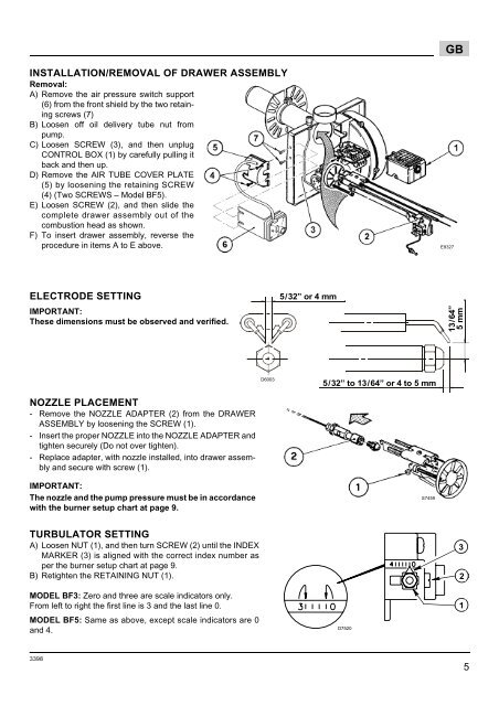
GBINSTALLATION/REMOVAL OF DRAWER ASSEMBLYRemoval:A) Remove the air pressure switch support(6) from the front shield by the two retainingscrews (7)B) Loosen off oil delivery tube nut frompump.C) Loosen SCREW (3), and then unplugCONTROL BOX (1) by carefully pulling itback and then up.D) Remove the AIR TUBE COVER PLATE(5) by loosening the retaining SCREW(4) (Two SCREWS – Model <strong>BF</strong>5).E) Loosen SCREW (2), and then slide thecomplete drawer assembly out of thecombustion head as shown.F) To insert drawer assembly, reverse theprocedure in items A to E above.E9327ELECTRODE SETTINGIMPORTANT:These dimensions must be observed and verified.5/32” or 4 mm13/64”5 mmD60035/32” to 13/64” or 4 to 5 mmNOZZLE PLACEMENT- Remove the NOZZLE ADAPTER (2) from the DRAWERASSEMBLY by loosening the SCREW (1).- Insert the proper NOZZLE into the NOZZLE ADAPTER andtighten securely (Do not over tighten).- Replace adapter, with nozzle installed, into drawer assemblyand secure with screw (1).IMPORTANT:The nozzle and the pump pressure must be in accordancewith the burner setup chart at page 9.S7459TURBULATOR SETTINGA) Loosen NUT (1), and then turn SCREW (2) until the INDEXMARKER (3) is aligned with the correct index number asper the burner setup chart at page 9.B) Retighten the RETAINING NUT (1).MODEL <strong>BF</strong>3: Zero and three are scale indicators only.From left to right the first line is 3 and the last line 0.MODEL <strong>BF</strong>5: Same as above, except scale indicators are 0and 4.D752032133985