Laboratory Testing of Fatigue Crack Growth in Geosynthetically ...
Laboratory Testing of Fatigue Crack Growth in Geosynthetically ...
Laboratory Testing of Fatigue Crack Growth in Geosynthetically ...
- No tags were found...

You also want an ePaper? Increase the reach of your titles
YUMPU automatically turns print PDFs into web optimized ePapers that Google loves.
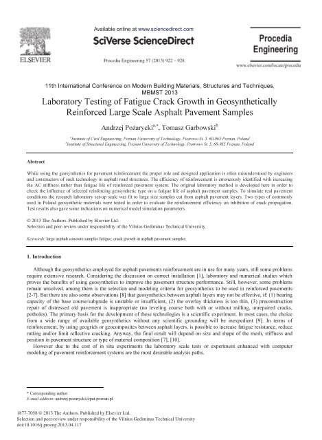
Available onl<strong>in</strong>e at www.sciencedirect.comProcedia Eng<strong>in</strong>eer<strong>in</strong>g 57 ( 2013 ) 922 – 92811th International Conference on Modern Build<strong>in</strong>g Materials, Structures and Techniques,MBMST 2013<strong>Laboratory</strong> <strong>Test<strong>in</strong>g</strong> <strong>of</strong> <strong>Fatigue</strong> <strong>Crack</strong> <strong>Growth</strong> <strong>in</strong> <strong>Geosynthetically</strong>Re<strong>in</strong>forced Large Scale Asphalt Pavement SamplesAndrzej Pożarycki a,∗ , Tomasz Garbowski ba Institute <strong>of</strong> Civil Eng<strong>in</strong>eer<strong>in</strong>g, Poznan University <strong>of</strong> Technology, Piotrowo St. 5, 60-965 Poznan, Polandb Institute <strong>of</strong> Structural Eng<strong>in</strong>eer<strong>in</strong>g, Poznan University <strong>of</strong> Technology, Piotrowo St. 5, 60-965 Poznan, PolandAbstractWhile us<strong>in</strong>g the geosynthetics for pavement re<strong>in</strong>forcement the proper role and designed application is <strong>of</strong>ten misunderstood by eng<strong>in</strong>eersand constructors <strong>of</strong> such technology <strong>in</strong> asphalt road structures. The efficiency <strong>of</strong> re<strong>in</strong>forcement is erroneously identified with <strong>in</strong>creas<strong>in</strong>gthe AC stiffness rather than fatigue life <strong>of</strong> re<strong>in</strong>forced pavement system. The orig<strong>in</strong>al laboratory method is developed here <strong>in</strong> order tocheck the <strong>in</strong>fluence <strong>of</strong> selected re<strong>in</strong>forc<strong>in</strong>g geosynthetic type on a fatigue life <strong>of</strong> asphalt pavement samples. To simulate real pavementconditions the research laboratory set-up scale was fit to large size samples cut from asphalt pavement layers. Two types <strong>of</strong> commonlyused <strong>in</strong> Poland geosynthetic materials were tested <strong>in</strong> order to evaluate the re<strong>in</strong>forcement efficiency on <strong>in</strong>hibition <strong>of</strong> crack propagation.Test results also gave some <strong>in</strong>dications on numerical model simulation parameters.© 2013 The Authors. Published by Elsevier by Elsevier Ltd. Ltd.Selection and peer-review under under responsibility <strong>of</strong> the <strong>of</strong> Vilnius the Vilnius Gedim<strong>in</strong>as Gedim<strong>in</strong>as Technical Technical UniversityUniversity.Keywords: large asphalt concrete samples fatigue; crack growth <strong>in</strong> asphalt pavement samples.1. IntroductionAlthough the geosynthetics employed for asphalt pavements re<strong>in</strong>forcement are <strong>in</strong> use for many years, still some problemsrequire extensive research. Consider<strong>in</strong>g the discussion on correct <strong>in</strong>stallation [1], laboratory and numerical studies whichproves the benefits <strong>of</strong> us<strong>in</strong>g geosynthetics to improve the pavement structure performance. Still, however, some problemsrema<strong>in</strong> unsolved, among them is the selection and model<strong>in</strong>g criteria for geosynthetics to be used <strong>in</strong> re<strong>in</strong>forced pavements[2-7]. But there are also some observations [8] that geosynthetics between asphalt layers may not be effective, if: (1) bear<strong>in</strong>gcapacity <strong>of</strong> the base course/subgrade is unstable or <strong>in</strong>sufficient, (2) the overlay thickness is too th<strong>in</strong>, (3) preconstructionrepair <strong>of</strong> distressed old pavement is <strong>in</strong>appropriate (no level<strong>in</strong>g course both with or without mill<strong>in</strong>g, unrepaired cracks,potholes). The primary basis for the development <strong>of</strong> these technologies is a scientific experiment. In most cases, the choicefrom a wide range <strong>of</strong> available geosynthetics without any scientific ground<strong>in</strong>g will be <strong>in</strong>expedient [9]. In terms <strong>of</strong>re<strong>in</strong>forcement, by us<strong>in</strong>g geogrids or geocomposites between asphalt layers, is possible to <strong>in</strong>crease fatigue resistance, reducerutt<strong>in</strong>g and/or limit reflective crack<strong>in</strong>g. Anyway, the f<strong>in</strong>al result will depend on size and shape <strong>of</strong> the mesh, stiffness andposition <strong>in</strong> pavement structure or type <strong>of</strong> material composition [7], [10].However due to the cost <strong>of</strong> <strong>in</strong> situ experiments the laboratory scale tests or experiment enhanced with computermodel<strong>in</strong>g <strong>of</strong> pavement re<strong>in</strong>forcement systems are the most desirable analysis paths.* Correspond<strong>in</strong>g author.E-mail address: andrzej.pozarycki@put.poznan.pl1877-7058 © 2013 The Authors. Published by Elsevier Ltd.Selection and peer-review under responsibility <strong>of</strong> the Vilnius Gedim<strong>in</strong>as Technical Universitydoi: 10.1016/j.proeng.2013.04.117
Andrzej Pożarycki and Tomasz Garbowski / Procedia Eng<strong>in</strong>eer<strong>in</strong>g 57 ( 2013 ) 922 – 928923The work [11-12] presents, that durability, re<strong>in</strong>forced pavement lifetime prediction analysis and grad<strong>in</strong>g <strong>of</strong> geosyntheticasphalt <strong>in</strong>terlayer systems can be obta<strong>in</strong>ed by fatigue crack growth test<strong>in</strong>g with the wedge splitt<strong>in</strong>g test <strong>in</strong>stead <strong>of</strong> the mostcommonly used beams and bend<strong>in</strong>g tests [13]. Based on such experiment they reported that SAMI and SAMI + asphaltre<strong>in</strong>forcement asphalt <strong>in</strong>terlayer systems outperform standard asphalt re<strong>in</strong>forcement systems (asphalt emulsion spray<strong>in</strong>g)and non-<strong>in</strong>terlayer systems by far, especially at low temperatures and high loads.Experimental data clearly evidences the beneficial, though rather qualitative, character <strong>of</strong> engaged geosynthetics. Amongmany available <strong>in</strong> the literature method <strong>of</strong> model<strong>in</strong>g the crack propagation <strong>in</strong> composite materials, the embeddeddiscont<strong>in</strong>uity, constitutive smeared crack<strong>in</strong>g [14], or X-FEM [15] seem to be frequently used by various researchers tocapture the crack growth effect. In the discrete crack propagation formulation a l<strong>in</strong>ear elastic fracture mechanics is usuallyemployed, on the other hand for the constitutive model<strong>in</strong>g <strong>of</strong> crack the damage mechanics is used. The discreet and smearedapproaches are different <strong>in</strong> nature but both require a particular set <strong>of</strong> parameter <strong>in</strong> order to properly simulate fractur<strong>in</strong>g anddegradation <strong>of</strong> material stiffness dur<strong>in</strong>g fatigue test. Unfortunately not all <strong>of</strong> the needed parameters are easily accessible.Therefore the careful choice <strong>of</strong> proper crack model<strong>in</strong>g technique has to be made based on available experimental data anddesired model<strong>in</strong>g expectations. Dur<strong>in</strong>g the fatigue test <strong>of</strong>ten more than millions <strong>of</strong> load<strong>in</strong>g cycles are generated therefore thecrack clos<strong>in</strong>g and open<strong>in</strong>g (due to cycl<strong>in</strong>g load<strong>in</strong>g) and self-heal<strong>in</strong>g <strong>of</strong> visco-elasto-plastic materials seem to be an importantphenomenon. In order to capture such behavior the proper material model which is capable to describe compressive andtensile stiffness degradation separately (e.g. [14], [16]) should be employed. By hav<strong>in</strong>g <strong>in</strong>dependent material behavior <strong>in</strong>tension and compression one can observe a recovery <strong>of</strong> progressive damage especially when material switches from tensionto compression and vice versa.However the task <strong>of</strong> pavement model<strong>in</strong>g is an example that confirms the thesis, that relatively simple eng<strong>in</strong>eer<strong>in</strong>gapproach <strong>of</strong> analysis <strong>of</strong> a layered system is a better approximation to the reality than the mathematically exact solution [17].2. Models <strong>of</strong> composites with isotropic matrix re<strong>in</strong>forced with regular gridHere the attention is given to the group <strong>of</strong> theoretical solutions, which may <strong>in</strong>clude alternative models <strong>of</strong> re<strong>in</strong>forcedconcrete pavement construction [18]. The composite material consist<strong>in</strong>g <strong>of</strong> a discrete grid embedded <strong>in</strong> the m<strong>in</strong>eral-asphaltmatrix can be further simplified through e.g. homogenization. Alternatively, if the composite is modeled as layered structure<strong>in</strong> the frame <strong>of</strong> isotropic l<strong>in</strong>ear theory <strong>of</strong> elasticity, the re<strong>in</strong>forcement can be treated as an equivalent layer with f<strong>in</strong>itethickness.2.1 Employment the elementary homogenizationSelected for analysis examples are based on geosynthetics made <strong>of</strong> glass fibers. The first is the geogrid and the other is ageocomposites, see Table 1.Table 1 Parameters <strong>of</strong> geosynthetics chosen for analysisa) GEOGRID ::GlassGrid 8550::Tensile strength:Grid elongation at break:Grid size:Young`s modulus <strong>of</strong> the glass filaments:Mass per unit area:Adhesive back<strong>in</strong>g:b) GEOCOMPOSITES ::PGM-G 100/100::Tensile strength:Grid elongation at break:Mesh width <strong>of</strong> the glass filaments:Young`s modulus <strong>of</strong> the glass filaments:Mass per unit area:Asphalt retention:Strength at 2% stra<strong>in</strong>:50 × 50 kN/m< 5%,25 × 25 mm,73 000 MPa,185 g/m2,pressure sensitive.100 × 100 kN/m,< 3%,40 × 40 mm,73 000 MPa,430 g/m 2 ,1.1 kg/m 2 ,68 × 68 kN/m.
924 Andrzej Pożarycki and Tomasz Garbowski / Procedia Eng<strong>in</strong>eer<strong>in</strong>g 57 ( 2013 ) 922 – 928To determ<strong>in</strong>e the elastic parameters <strong>of</strong> the section, the homogenization method described <strong>in</strong> [18, 20] is used here. Due tothe negligible stiffness <strong>of</strong> geocomposites, the calculation was carried out only for the geogrid (Table 1a). The geometry <strong>of</strong>the sample was prepared similar to the size <strong>of</strong> A4 format.Table 2 Results <strong>of</strong> macroscopic geometry measurements GG8550The rema<strong>in</strong><strong>in</strong>g parameters needed to determ<strong>in</strong>e the characteristics <strong>of</strong> theequivalent layer are calculated from the formulas:Width <strong>of</strong> rib, mma1a21.5 1.5Grid size, mmb1b225 25Thickness <strong>of</strong> ribg1g21.5 1.5Distance between ribs, mma1 + b1 a1 + b126.5 26.5ua1= u =( a + b )1 21 1a ⋅g ⋅ ( a + b )1 1 1 1, p 1= p2=( a1+ b1) ⋅ ( a1+ b1) ⋅2g1, p1+ p2 + pm+ pp= 1(1)where: u 1= u2, p 1= p2- respectively percentage <strong>of</strong> the ribs area <strong>in</strong> the width and length <strong>of</strong> the grid and their volumefraction <strong>in</strong> the grid structure,p p content <strong>of</strong> space unfilled by the matrix,p m part <strong>of</strong> matrix <strong>in</strong> total volume <strong>of</strong> grid,Consider<strong>in</strong>g the model <strong>of</strong> geogrid, which uses the values <strong>of</strong> geometrical measurements and the parameters declared bythe manufacturer (gathered <strong>in</strong> Table 1) a secant modulus was calculated by Equation (2):Fm1E = ⋅u g ⋅εwhere:F m maximum tensile force kN/m,u i part <strong>of</strong> the material <strong>in</strong> the strip <strong>of</strong> the grid mm/mmg i thickness <strong>of</strong> the rib <strong>in</strong> the „i th ” direction mm,є m grid elongation at break mm/mm.i i m=11 778 MPa (2)F<strong>in</strong>ally, us<strong>in</strong>g the method which converts the basic features <strong>of</strong> the geogrids, from the real model to its surrogate, anequivalent E K modulus and Poisson’s ratio <strong>of</strong> HMA composite with re<strong>in</strong>forcement can be calculated [18].2 2 2mm−ν− ν2κ+ pmE[2(1 −ν−2 ν ) κ + 3 p (7 −8 ν) κ+ 45 p ]EK( E, ν, pm, κ ) =12(1 2 ) 45[MPa]where:E AC stiffness, MPa;E k Composite stiffness (AC + Geogrid), MPa;E zi Geogrid stiffness along “i” direction;2(1−ν−2 ν ) κ+ 15ν⋅p E Eνk( ν, pm, κ ) = , κ = p + p4(1 −ν−2 ν2) κ+ 15 pm z1 z21 2m E E, (3)
Andrzej Pożarycki and Tomasz Garbowski / Procedia Eng<strong>in</strong>eer<strong>in</strong>g 57 ( 2013 ) 922 – 928925ν Poisson ratio <strong>of</strong> AC;sν k Poisson ratio <strong>of</strong> composite (AC+Geogrid) MPa.Tab. 3 Theoretical re<strong>in</strong>forcement efficiency <strong>of</strong> composite structure (AC+geogrid)AC featuresComposite <strong>of</strong> AC and geogridTheoreticalRe<strong>in</strong>forcementEfficiencyPoisson coefficient[---]Stiffness modulus,[MPa]Coefficient, κ[---]Poisson coefficientν K [---]Stiffness modulusE K, [MPa] [%]Summer 0.4 3 000 0.222 0.39 2949 -1.7Spr<strong>in</strong>g 0.3 10 000 0.067 0.30 9545 -4.5W<strong>in</strong>ter 0.25 18 000 0.037 0.25 17092 -5.03. The laboratory experimentBy limit<strong>in</strong>g the analysis to the basic scope <strong>of</strong> the calculation <strong>of</strong> the stress / stra<strong>in</strong> only, a beneficial effect <strong>of</strong>re<strong>in</strong>forcement is likely to “reveal” only <strong>in</strong> situations <strong>in</strong> which used geosynthetics will have a significant stiffness (e.g. glassfiber mesh <strong>in</strong> the matrix epoxy res<strong>in</strong>). The experiment is expected to provide the results <strong>of</strong> the analyzes lead<strong>in</strong>g to answerthe question concern<strong>in</strong>g the effectiveness and mean<strong>in</strong>g <strong>of</strong> re<strong>in</strong>forcement <strong>of</strong> asphalt layers by geosynthetics with lowstiffness.3.1. The general depiction <strong>of</strong> experimentSamples for laboratory tests have been cut from the test section pavement described <strong>in</strong> detail [19]. At the laboratory,there was built a set-up for fatigue tests <strong>of</strong> large-scale cores, us<strong>in</strong>g a Schenck strength device. <strong>Laboratory</strong> set-up wasconstructed based on own concept, by us<strong>in</strong>g HBM measurement system. Dur<strong>in</strong>g the tests the follow<strong>in</strong>g values weremeasured: (1) force, (2) displacements on the surface <strong>of</strong> plate sample and (3) contractual length <strong>of</strong> crack <strong>in</strong> the area <strong>of</strong>potential <strong>in</strong>fluence <strong>of</strong> artificial notch with a height around 8 cm (Fig. 1a). The observation area was covered with a smooth,very th<strong>in</strong> layer <strong>of</strong> gypsum <strong>in</strong> white, thus facilitat<strong>in</strong>g to observe the process <strong>of</strong> crack propagation <strong>in</strong> successive moments <strong>of</strong>time dur<strong>in</strong>g fatigue tests. <strong>Crack</strong> growth propagation was determ<strong>in</strong>ed visually by us<strong>in</strong>g image analysis techniques. This studycompares three groups <strong>of</strong> asphalt <strong>in</strong>terlayer systems. In the Fig. 1b, the first row shows the condition <strong>of</strong> the sample prior t<strong>of</strong>atigue test<strong>in</strong>g, and <strong>in</strong> the second row are aligned sample images, shortly before the end <strong>of</strong> fatigue tests.(a)(b)<strong>Crack</strong> observation areasReference Sample(P02)PGM-G100/100(P25)GG8550(P30)Fig. 1. (a) Orig<strong>in</strong>al laboratory fatigue crack growth <strong>in</strong>vestigation set-up (the plate dimensions: 1.0 × 1.0 × 0.15 [m]); (b) laboratory fatigue crack growthstudy cases (horizontal l<strong>in</strong>es on particular images are called here contractual levels <strong>of</strong> crack growth observation)The follow<strong>in</strong>g list shows the chosen for comparison the most commonly used geosynthetic materials for flexiblepavement re<strong>in</strong>forcement <strong>in</strong> Poland:• Reference samples (P02);• PGM-G 100/100 (P25);
926 Andrzej Pożarycki and Tomasz Garbowski / Procedia Eng<strong>in</strong>eer<strong>in</strong>g 57 ( 2013 ) 922 – 928• Glass Grid 8550 (P30).3.2. Detailed assumptions <strong>of</strong> performed experimentMany previous attempts to a target research programme, helped to develop a solution, which guarantee their completion.It was considered that the most beneficial effect <strong>of</strong> “simplification-results quality” relationship was obta<strong>in</strong>ed with largesizedsamples placed on steel beams along the opposite edges <strong>of</strong> the sample <strong>in</strong> parallel to the longitud<strong>in</strong>al axle l<strong>in</strong>e <strong>of</strong>artificial crack. <strong>Crack</strong> growth propagation tests carried out on the assumption that the vertical displacement rate, measuredat the surface <strong>of</strong> the sample <strong>in</strong> the load axis is constant and is equal to 1 mm/hour (Fig. 2).Dur<strong>in</strong>g the measurements the average value <strong>of</strong> the load, to satisfy the above condition was F = 14 kN. The frequency <strong>of</strong>s<strong>in</strong>usoidal change <strong>of</strong> load cycles was f = 10 Hz. Average temperature <strong>of</strong> the samples dur<strong>in</strong>g fatigue tests was T = 13 ± 1 °C.Fig. 2. An example <strong>of</strong> (a) constant vertical displacement rate; (b) m<strong>in</strong>imal and maximal envelope values <strong>of</strong> s<strong>in</strong>usoidal load4. The experimental resultsThis section summarizes the results <strong>of</strong> laboratory tests. Contractual level <strong>of</strong> crack tip <strong>in</strong> relation to maximal value <strong>of</strong>s<strong>in</strong>usoidal force amplitude is shown <strong>in</strong> the Fig. 3. This analysis compares the values <strong>of</strong> the forces needed to damage largesize samples, re<strong>in</strong>forced with considered types <strong>of</strong> geosynthetic materials.Fig. 3. Contractual level <strong>of</strong> crack tip <strong>in</strong> relation to maximal value <strong>of</strong> s<strong>in</strong>usoidal force valueOn the <strong>in</strong>dividual graphs (Fig. 4) one can observe the propagation <strong>of</strong> fatigue cracks <strong>in</strong> the re<strong>in</strong>forced samples alwayscompared to the sample results under the same test<strong>in</strong>g conditions but without re<strong>in</strong>forcement (called here the reference modelP02).Samples: P02 vs P30 (GlassGrid 8550) - Mass per unit area: 185 g/m 2 ,
Andrzej Pożarycki and Tomasz Garbowski / Procedia Eng<strong>in</strong>eer<strong>in</strong>g 57 ( 2013 ) 922 – 928927Samples: P02 vs P25 (PGM-G 100/100) - Mass per unit area: 430 g/m 2Fig. 4 The average paths <strong>of</strong> crack propagation <strong>in</strong> samples re<strong>in</strong>forced with chosen geosynthetics and the reference samples5. <strong>Laboratory</strong> and theoretical results discussionThe role <strong>of</strong> the re<strong>in</strong>forcement by geosynthetic materials with low flexural stiffness is checked here. First, us<strong>in</strong>g one <strong>of</strong> themethods <strong>of</strong> homogenization <strong>of</strong> composite with re<strong>in</strong>forced layer, where equivalent stiffness <strong>of</strong> re<strong>in</strong>forced course is computed(i.e. stiffness <strong>of</strong> the composite AC with geogrid). Based on the obta<strong>in</strong>ed results, as expected, the lack <strong>of</strong> efficiencies <strong>of</strong>re<strong>in</strong>forcement was observed (negative values <strong>in</strong> Tab. 3, last column). The example <strong>of</strong> calculation concerned only geogrid,however, due to the similar properties <strong>of</strong> the second material, one can expect the same results. In other words, if one th<strong>in</strong>ks<strong>of</strong> re<strong>in</strong>forcements as a stiffness improvement <strong>of</strong> the composite, formed from a mixture <strong>of</strong> asphalt and re<strong>in</strong>forc<strong>in</strong>g layer, thanthe mean<strong>in</strong>g <strong>of</strong> the application <strong>of</strong> the grid GG8550 or geocomposites PGM 100/100 for such solutions is questionable.The overall picture <strong>of</strong> re<strong>in</strong>forcement <strong>in</strong> these materials dramatically changes when subjected to the fatigue analysis. Inorder to check the fatigue resistance a large-scale laboratory test<strong>in</strong>g <strong>of</strong> the sample plate cut from the experimental section <strong>of</strong>asphalt layers is exam<strong>in</strong>ed here. Assess<strong>in</strong>g the effectiveness <strong>of</strong> the re<strong>in</strong>forcement <strong>in</strong> the form <strong>of</strong> relative measure whichtakes <strong>in</strong>to account only the number <strong>of</strong> cycles until the crack tip reaches the reference <strong>of</strong> + 2 cm (see Fig. 4) the follow<strong>in</strong>gobservations was taken:• The <strong>in</strong>crease <strong>of</strong> the fatigue life by 16% for samples re<strong>in</strong>forced with geogrid;• The <strong>in</strong>crease by 37% <strong>in</strong> the case <strong>of</strong> geocomposites` re<strong>in</strong>forcement.6. ConclusionsThe results showed that the test<strong>in</strong>g protocol presented <strong>in</strong> the paper is suitable for laboratory study<strong>in</strong>g the performance <strong>of</strong>re<strong>in</strong>forced large scale samples, mak<strong>in</strong>g possible to f<strong>in</strong>d out the difference between fatigue life <strong>of</strong> samples re<strong>in</strong>forced withdifferent materials. The results <strong>of</strong> the analysis revealed that:• Theoretical analysis <strong>of</strong> the re<strong>in</strong>forcement’s <strong>in</strong>fluence, reduced to assess the impact on the stiffness <strong>of</strong> the surrogatemodels <strong>of</strong> composite shows no improvement if re<strong>in</strong>forcement material has no bend<strong>in</strong>g stiffness.• The same types <strong>of</strong> materials (with no bend<strong>in</strong>g stiffness) assessed for fatigue life <strong>in</strong> laboratory conditions, on the largescalespecimens cut from the asphalt pavement layers, revealed the beneficial properties <strong>of</strong> such solutions. Geogrids<strong>in</strong>creased fatigue life by 16% <strong>in</strong> the case <strong>of</strong> geocomposites was an <strong>in</strong>crease over 35%.• The impact <strong>of</strong> geosynthetics should be judged only on the basis <strong>of</strong> the analysis which takes <strong>in</strong>to account the phenomenon<strong>of</strong> fatigue due to cyclic loads. There is a need to develop the theoretical methods to optimize the pavement design withthe use <strong>of</strong> re<strong>in</strong>forcement technologies.
928 Andrzej Pożarycki and Tomasz Garbowski / Procedia Eng<strong>in</strong>eer<strong>in</strong>g 57 ( 2013 ) 922 – 928References[1] Pasqu<strong>in</strong>i, E., Bocci M., Ferrotti, G., Canestrari F., 2012. <strong>Laboratory</strong> characterisation and field validation <strong>of</strong> geogrid-re<strong>in</strong>forced asphalt pavements, RoadMaterials and Pavement Design, iFirst, pp. 1–19.[2] Y<strong>in</strong>, J. H., 2000.Comparative model<strong>in</strong>g study <strong>of</strong> re<strong>in</strong>forced beam on elastic foundation, Journal <strong>of</strong> Geotechnical and Geoenvironmental Eng<strong>in</strong>eer<strong>in</strong>g126(3), pp. 265-271.[3] Perk<strong>in</strong>s, S. W., Edens, M. Q., 2002. F<strong>in</strong>ite Element and Distress Models for Geosynthetic-re<strong>in</strong>forced Pavements, The International Journal <strong>of</strong> PavementEng<strong>in</strong>eer<strong>in</strong>g 3(4), pp.239-250.[4] Perk<strong>in</strong>s, S.W., Edens, M. Q., 2003. A Design Model for Geosynthetic-re<strong>in</strong>forced Pavements, The International Journal <strong>of</strong> Pavement Eng<strong>in</strong>eer<strong>in</strong>g 4(1),pp. 37–50.[5] Dong, Y. L., Han, J., Bai, X. H., 2011. Numerical analysis <strong>of</strong> tensile behavior <strong>of</strong> geogrids with rectangular and triangular apertures, Geotextiles andGeomembranes 29, pp. 83-91.[6] Zornberg, J. G., 2011. Advances <strong>in</strong> the use <strong>of</strong> geosynthetics <strong>in</strong> pavement design, Geosynthetics India’11, 23-24 September 2011, IIT Madras, Chennai,KN-3 – KN-21.[7] Galve, J. P., Gutiérrez, F., Guerrero, J., Alonso, J., Diego, I., 2012. Optimiz<strong>in</strong>g the application <strong>of</strong> geosynthetics to roads <strong>in</strong> s<strong>in</strong>khole-prone areas on thebasis <strong>of</strong> hazard models and cost-benefit analyses, Geotextiles and Geomembranes 34, pp.80-92.[8] Zou, W. L., Wang, Z., Zhang, H. M., 2007. Field Trial for Asphalt Pavements Re<strong>in</strong>forced with Geosynthetics and Behavior <strong>of</strong> Glass-Fiber Grids,Journal <strong>of</strong> Performance <strong>of</strong> Constructed Facilities 21(5), pp. 361-367.[9] Laur<strong>in</strong>avičius, A., Og<strong>in</strong>skas, R., 2006. Experimental research on the development <strong>of</strong> rutt<strong>in</strong>g <strong>in</strong> asphalt concrete pavements re<strong>in</strong>forced with geosyntheticmaterials, Journal <strong>of</strong> Civil Eng<strong>in</strong>eer<strong>in</strong>g and Management XII(4), pp. 311–317.[10] Ferrotti, G., Canestrari, F., Pasqu<strong>in</strong>i, E., Virgili, A., 2012. Experimental evaluation <strong>of</strong> the <strong>in</strong>fluence <strong>of</strong> surface coat<strong>in</strong>g on fiberglass geogridperformance <strong>in</strong> asphalt pavements, Geotextiles and Geomembranes 34, pp. 11-18.[11] Tschegg, E. K., Jamek, M., Lugmayr, R., 2012. <strong>Crack</strong> growth behaviour <strong>in</strong> geosynthetic asphalt <strong>in</strong>terlayer systems, Road Materials and PavementDesign 13(1), pp.156–170.[12] Jamek, M., Tschegg E. K., Lugmayr, R., 2012. Mechanical and fracture–mechanical properties <strong>of</strong> geosynthetic re<strong>in</strong>forced asphalt systems, <strong>Fatigue</strong> &Fracture <strong>of</strong> Eng<strong>in</strong>eer<strong>in</strong>g Materials Structures 35, pp. 648–657.[13] Read, J. M., 2000. New Method for Measur<strong>in</strong>g <strong>Crack</strong> Propagation <strong>in</strong> Asphalts, International Journal <strong>of</strong> Pavement Eng<strong>in</strong>eer<strong>in</strong>g 1(1), pp. 15-34.[14] Lee, J., Fenves, G. L., 1998, Plastic-damage model for cyclic load<strong>in</strong>g <strong>of</strong> concrete structures, ASCE Journal <strong>of</strong> Eng<strong>in</strong>eer<strong>in</strong>g Mechanics 124(8), pp. 892-900.[15] Belytschko, T., Black, T., 1999. Elastic crack growth <strong>in</strong> f<strong>in</strong>ite elements with m<strong>in</strong>imal remesh<strong>in</strong>g, Internat. J. Numer. Methods Engrg. 45, pp. 601-620.[16] Lubl<strong>in</strong>er, J., Oliver, J., Oller, S. and Onate, E., 1989. A plastic-damage model for concrete, Int. Journal <strong>of</strong> Solids and Structures 25, pp. 299-326.[17] Ullidtz, P., 2002. Analytical Tools for Design <strong>of</strong> Flexible Pavements, <strong>in</strong> 8th ISAP Conference, Copenhagen, August 2002.[18] Sybilski, D., Jezierska, D., Maliszewski, M., Mularzuk, R., Jemioło, S. 2006. Analysis <strong>of</strong> pavement re<strong>in</strong>forcement ability with geogrids by us<strong>in</strong>g thef<strong>in</strong>ite element method. F<strong>in</strong>al report, Road and Bridge Research Institute, Pavement Technology Division, Warsaw, June 2006r (<strong>in</strong> Polish).[19] Grabowski, W., Pożarycki, A. 2008. An Energy Absorption In Large Dimension Asphalt Pavement Samples Re<strong>in</strong>forced With Geosynthetics,Foundations <strong>of</strong> Civil and Environmental Eng<strong>in</strong>eer<strong>in</strong>g 1.[20] Perk<strong>in</strong>s, S.W., Christopher, B. R., Cuelho, E. L., Eiksund, G. R., H<strong>of</strong>f, I., Schwartz, Ch. W., Svanø, G., Want, A., 2004. Development <strong>of</strong> DesignMethods for Geosynthetic Re<strong>in</strong>forced Flexible Pavements, F<strong>in</strong>al Report FHWA Report Reference: DTFH61-01-X-00068, May 25, 2004. Department<strong>of</strong> Civil Eng<strong>in</strong>eer<strong>in</strong>g, Montana State University – Bozeman, Bozeman, Montana 59717.