Reference Architecture for Remote Operations of Offshore Wind Farms
Reference Architecture for Remote Operations of Offshore Wind Farms
Reference Architecture for Remote Operations of Offshore Wind Farms
- No tags were found...

Create successful ePaper yourself
Turn your PDF publications into a flip-book with our unique Google optimized e-Paper software.
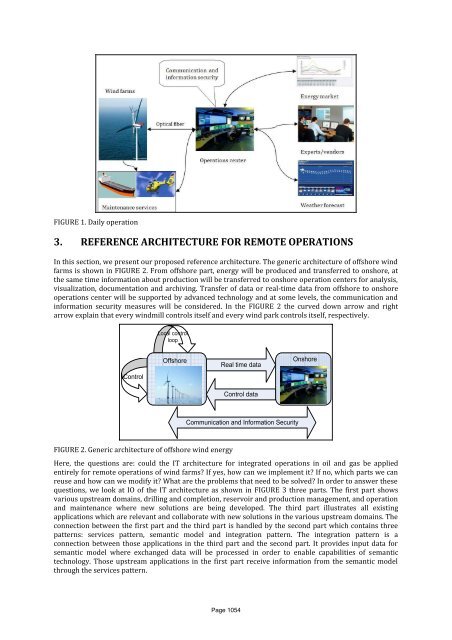
FIGURE 1. Daily operation3. REFERENCE ARCHITECTURE FOR REMOTE OPERATIONSIn this section, we present our proposed reference architecture. The generic architecture <strong>of</strong> <strong>of</strong>fshore windfarms is shown in FIGURE 2. From <strong>of</strong>fshore part, energy will be produced and transferred to onshore, atthe same time in<strong>for</strong>mation about production will be transferred to onshore operation centers <strong>for</strong> analysis,visualization, documentation and archiving. Transfer <strong>of</strong> data or real-time data from <strong>of</strong>fshore to onshoreoperations center will be supported by advanced technology and at some levels, the communication andin<strong>for</strong>mation security measures will be considered. In the FIGURE 2 the curved down arrow and rightarrow explain that every windmill controls itself and every wind park controls itself, respectively.Local controlloopControl<strong>Offshore</strong>Real time dataControl dataOnshoreCommunication and In<strong>for</strong>mation SecurityFIGURE 2. Generic architecture <strong>of</strong> <strong>of</strong>fshore wind energyHere, the questions are: could the IT architecture <strong>for</strong> integrated operations in oil and gas be appliedentirely <strong>for</strong> remote operations <strong>of</strong> wind farms? If yes, how can we implement it? If no, which parts we canreuse and how can we modify it? What are the problems that need to be solved? In order to answer thesequestions, we look at IO <strong>of</strong> the IT architecture as shown in FIGURE 3 three parts. The first part showsvarious upstream domains, drilling and completion, reservoir and production management, and operationand maintenance where new solutions are being developed. The third part illustrates all existingapplications which are relevant and collaborate with new solutions in the various upstream domains. Theconnection between the first part and the third part is handled by the second part which contains threepatterns: services pattern, semantic model and integration pattern. The integration pattern is aconnection between those applications in the third part and the second part. It provides input data <strong>for</strong>semantic model where exchanged data will be processed in order to enable capabilities <strong>of</strong> semantictechnology. Those upstream applications in the first part receive in<strong>for</strong>mation from the semantic modelthrough the services pattern.Page 1054