<strong>WINNER</strong> <strong>D2.5</strong> <strong>v1.0</strong>APL1RSHop 2RANHop 1L4L2L3TerminalFigure 3-2: Schematic picture of a 2-hop network connectionIn the sequel, there is a need to describe when a device (say an AP) is receiving and transmitting on acertain link. This will be noted by Ri and Ti, respectively, where i is the number of the link. Thus, lookingat Figure 3-2, the names T1 and R4 denote the communication from/to the AP, and T2, T4, R1, R3 denotethe actions of the RS, and so on.In the following sections we investigate several alternatives for the duplex schemes in the two hops. TheTDD based schemes have advantages and are most often considered for multi-hop scenarios in theliterature, but in the following also other possibilities based on FDD are included.3.4.1 Scheme AIn scheme A, all links use the same carrier frequency, and the 4 links are separated by means of timedivision, that is both hops make use of pure TDD. This is depicted in Figure 3-3 and Figure 3-4whereessentially the same information is displayed but where different aspects of the forwarding process arehigh lighted. Since similar pictures are given for all duplex possibilities short descriptions how tounderstand the pictures are given in this section.The numerical figure 1,2,3 or 4 on the arrows symbolises the links L1, L2, L3, or L4, respectively. Theline marked ‘carrier’ on which an arrow points or from which it originates depicts which carrier is usedfor which of the four links (for scheme A only one carrier/line is used).In the left part of Figure 3-3, the use of the carrier is highlighted, while the right part focuses on thetemporal usage, that is, when the links are activated in relation to each other. Note that we have 4 (notnecessarily equal sized) distinct slots in this scheme. The Figure 3-4 combines the spectral and temporalviews so as to give a simple overview of the scheme.This only requires the allocation of one carrier, but on the other hand the available nominal bandwidth isreduced since the single carrier has to be split into four mutually exclusive parts. In a well-designedsystem, such a reduction is more than offset by the increased capacity due to the hopping.Page 34 (121)
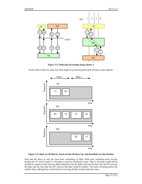
<strong>WINNER</strong> <strong>D2.5</strong> <strong>v1.0</strong>Slot1 2 3 4APMTAPT1R4R2T314carrier^RSR1 T4T2R323RSMTFigure 3-3: Multi hop forwarding using scheme AIf more than 2 hops are used, time slots might be reused along the chain of hops to gain capacity.Hop 1 Hop 2frequencyT1APR4frequencyR1RST4 T2 R3timetimefrequencyMTR2T3timeFigure 3-4: Hops are divided by means of time division, Up- and downlinks by time divisionNote that the above is only the most basic scheduling of links. With more switching point cleverlylocated, the T1 and T2 (and T3, T4) phases could be interlaced in time. That is, the hops would still bedivided by means of time division albeit interlaced, but the delay between the first time the RS receivesthe data, and the first time the MT receives that data would be smaller. The more switching points, thesmaller delay, although the overall time for receiving all data would remain the same.Page 35 (121)