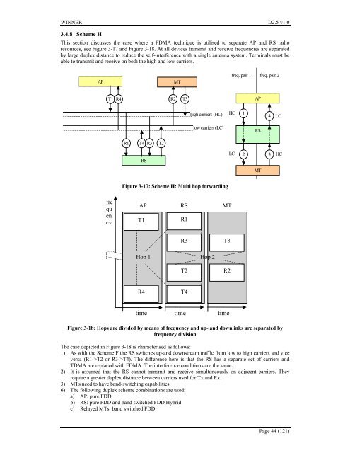
<strong>WINNER</strong> <strong>D2.5</strong> <strong>v1.0</strong>3.4.8 Scheme HThis section discusses the case where a FDMA technique is utilised to separate AP and RS radioresources, see Figure 3-17 and Figure 3-18. At all devices transmit and receive frequencies are separatedby large duplex distance to reduce the self-interference with a single antenna system. Terminals must beable to transmit and receive on both the high and low carriers.APMTfreq. pair 1 freq. pair 2T1R4R2T3APhigh carriers (HC)HC14LClow carriers (LC)RSR1 T4 R3 T2RSLC2 3HCMTFigure 3-17: Scheme H: Multi hop forwardingfrequencyAP RS MTT1R1R3T3Hop 1 Hop 2T2R2R4T4time time timeFigure 3-18: Hops are divided by means of frequency and up- and downlinks are separated byfrequency divisionThe case depicted in Figure 3-18 is characterised as follows:1) As with the Scheme F the RS switches up-and downstream traffic from low to high carriers and viceversa (R1->T2 or R3->T4). The difference here is that the RS has a separate set of carriers andTDMA are replaced with FDMA. The interference conditions are the same.2) It is assumed that the RS cannot transmit and receive simultaneously on adjacent carriers. Theyrequire a greater duplex distance between carriers used for Tx and Rx.3) MTs need to have band-switching capabilities6) The following duplex scheme combinations are used:a) AP: pure FDDb) RS: pure FDD and band switched FDD Hybridc) Relayed MTs: band switched FDDPage 44 (121)
<strong>WINNER</strong> <strong>D2.5</strong> <strong>v1.0</strong>3.4.9 Conclusion on duplex schemes for multi hopFrom the above descriptions and analysis, it seems that TDD based multi hop systems described inschemes A and B exhibit the least differences in behaviour when used in single hop and multihopsystems. Furthermore, there is no need for band-switched equipment or duplex filters in the MT. In B theRS might need band-switching capabilities, depending on how the scheduling is done.The scheme D uses FDD in terminals and FDD +band switched FDD in the RS, as well as duplex filtersin all types of equipment.The schemes C and E enable Half <strong>Duplex</strong> FDD operation at the MT, although band switching is neededin the RS.The schemes F and H seem less attractive since they rely on band switching capabilities in the userequipment. (A possibility could be to always have an even number of RSs, to allow for MTs withstandard band configurations.)In all cases the traditional roles of ‘uplink’ and ‘downlink’ are blurred, and difficulties might arise whenhandling interference scenarios.It is important to choose a scheme that enables MTs with low complexity in single-hop operation as wellas in multi-hop situations.Taking into account all of the above, multi hop solutions schemes A and B based on TDD seem to befavourable, although there might be interference and coordination issues that needs to be further studied.Some are addressed chapter 4.It should be noted that the IEEE802.16 standard [IEEE802.16] uses a scheme that is very similar toscheme A above, where the phase in which forwarding to/from the MT is completely under the control ofthe RS, and during which time the AP is simply idle.3.5 Combinations duplex methods/multiple access schemeIn this section some basic combinations of UL/DL multiple access schemes with duplex schemes areinvestigated. Since there seems to be a consensus regarding the DL scheme around an OFDM (or at leasta multi carrier, or MC, based) DL scheme, only this DL alternative is considered below. For the UL bothMC and single carrier (SC) based solutions are considered.One of the main reasons for having an UL scheme that differs from the OFDM DL, is that OFDM has ahigh peak-to-average ratio (PAR) which put large demands on the terminal power amplifier linearity,alternatively requires a power back-off that reduces the UL coverage. Therefore, schemes with a smallerPAR are preferred.The TDD and Half <strong>Duplex</strong> FDD based schemes have the advantage that much of the RF functionality canbe switched off when not transmitting or receiving in order to save power, which is especially importantfor the MTs. A continuous FDD based scheme does not have this advantage.One advantage of TDD is the possibility in some situations to exploit channel reciprocity for e.g. betterallocation strategies or beamforming. It would seem that having essentially the same signalling in the ULand DL would simplify channel estimation since measurements can be made on a per sub carrier basis,while for other SC-based UL schemes some signal processing is necessary. However, the amount ofsignalling processing is likely moderate in comparison to decoding and other operations. Of course, insome UL schemes like IFDMA and FDMA only a part of the spectrum is used and hence the AP canextract information only about this part. Having spectrum wide pilots transmitted at certain intervals cansolve this.Another reason why the choice of duplex method and the choice of multiple access method could beconnected is that interference characteristic experienced by the AP, RS or MT is connected to the choiceof duplex method. A TDD or Half <strong>Duplex</strong> FDD based scheme is inherently more ‘bursty’ than acontinuous transmission FDD system. However, regardless of the duplex method, the traffic is expectedto be quite bursty anyway since it most likely very packet oriented.This means that the air interface must be able to handle ‘bursty interference’ anyway within limits. Ofcourse, in the case of uncoordinated TDD cells the level of interference can probably be significantlyPage 45 (121)