

IST-2003-507581 WINNER D2.5 v1.0 Duplex ... - Celtic-Plus
IST-2003-507581 WINNER D2.5 v1.0 Duplex ... - Celtic-Plus
IST-2003-507581 WINNER D2.5 v1.0 Duplex ... - Celtic-Plus
- No tags were found...

You also want an ePaper? Increase the reach of your titles
YUMPU automatically turns print PDFs into web optimized ePapers that Google loves.
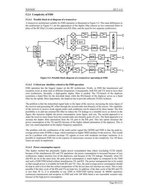
<strong>WINNER</strong> <strong>D2.5</strong> <strong>v1.0</strong>5.2.4 Complexity of FDD5.2.4.1 Possible block level diagram of a transceiverA transceiver architecture suitable for FDD operation is illustrated in Figure 5-2. The main differences tothe architecture in Figure 5-1 are the appearances of the duplex filter (shown as two connected filters inplace of the RF filter (1)) and a potential extra RX filter, and the need for two separate synthesizers.π/2LOqLOiSynth.DACDACPARREDUCTIONQILOqADCQπ/2Synt h.AGC logicRSSILOiADCIFigure 5-2: Possible block diagram of a transceiver operating in FDD5.2.4.2 Critical non -idealities related to the FDD operationFDD operation has the biggest impact on the RF architecture. Firstly, in FDD the transmission andreception occur at same time at different frequencies. Consequently, both RX and TX need to have theirown synthesizers. Secondly, a high-quality duplex filter is needed. The TX-branch of the duplexerconstitutes a band filter for the downlink band, while the RX-branch of the duplexer serves as a bandfilter for the uplink. Most importantly, the duplexer has to provide sufficient TX-RX isolation.The problem is that the transmitted signal leaks to the input of the receiver, increasing the noise figure ofthe receiver and generating DC offset through the second-order non-linearity of the mixers. The capabilityof the receiver to receive weak signals under such conditions can be improved by three means. The firstpossibility is to add one external RX filter to reduce the TX leakage to a tolerable level, as shown in thefigure; this increases slightly the power consumption, noise figure, and cost. The second approach is tomake the receiver more linear from the second-order non-linearity point-of-view. The third approach is toincrease the duplex filter attenuation from the TX port to the RX port. This last option increases thepower consumption of the TX and RX because of the higher inband attenuation of the duplexer. This isalso very much dependent on the duplex frequency separation.The problem with the combination of the multi-carrier signal like OFDM and FDD is that the peak-toaverage-power-ratio(PAPR) is large, which translates to higher IMD2 product in the receiver. This wouldnot be a problem with constant envelope TX signals or even with moderate envelope variations. It ispossible to implement FDD, but at the expense of unnecessary increase in the complexity. For AP theseissues are easier to implement.5.2.4.3 Power consumption aspectsThis duplex method has potentially higher power consumption than others (excluding CCD) mainlybecause of the simultaneous RX and TX operations: the power consumption is increased because of twosynthesizers, higher insertion loss of the duplexers, and because of the TX leakage. Naturally, when TXand RX are on at the same time, the peak power consumption is much higher as compared to the TDDand such a FDD/TDD hybrid without simultaneous TX and RX. The power management has to be scaledso that enough power is available for both RX and TX. Also, the total average power consumption shouldbe kept at such a level that the surface temperature of the device does not increase too much. This is onlypossible if the duty cycle of the RX and TX are kept low. In addition, if the duty cycle of the RX and TXis less than 50 %, it is preferable to use TDD or FDD/TDD hybrid instead. In MIMO operation,continuous transmission and reception in FDD and with 100 MHz band is not reasonable scenario onlybecause of the high power consumption.Page 88 (121)


