Maxima UL Construction #507B - McElroy Metal
Maxima UL Construction #507B - McElroy Metal
Maxima UL Construction #507B - McElroy Metal
Create successful ePaper yourself
Turn your PDF publications into a flip-book with our unique Google optimized e-Paper software.
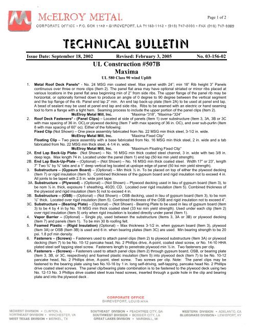
Page 1 of 2Technical BulletinIssue Date: September 18, 2002 Revised: February 3, 2005 No. 03-156-02<strong>UL</strong> <strong>Construction</strong> <strong>#507B</strong><strong>Maxima</strong><strong>UL</strong> 580 Class 90 wind Uplift1. <strong>Metal</strong> Roof Deck Panels* - No. 24 MSG min coated steel. Max panel width 24”; min 18” Rib height 3” Panelscontinuous over three or more clips (Item 2). The panel flat area may have optional striated or minor ribs placed atvarious locations in the panel flat area beginning min of 2” from side ribs. The upper flange of the panel rib may behorizontal, or optionally formed down to produce an angle of 0 degree to 90 degree between the vertical segmentand the top flange of the rib. Panel end lap 2” min. An end lap back-up plate (Item 2A) to be used at panel end lap.A bead of sealant may be used at panel end lap and side ribs. Ribs to be seamed with an electric or hand seamingtool to form a flange with a tight hem. Seaming process to include the upper portion of the panel clips (Item 2).<strong>McElroy</strong> <strong>Metal</strong> Mill, Inc.“<strong>Maxima</strong>-“318”, “<strong>Maxima</strong>-“324”2. Roof Deck Fasteners* - (Panel Clips) – Located at side of panels (Item 1) over substructure (Item 3, 3A, 3B or 3Cwith max spacing of 36 in. OC),or plywood decking (Item 7 with max spacing of 36 in. OC), and over sub-purlin (Item8 with max spacing of 60” oc). Either of the following:Fixed Clip (Not Shown) – One piece assembly fabricated from No. 22 MSG min thick steel, 3-1/2 in. wide.<strong>McElroy</strong> <strong>Metal</strong> Mill, Inc.“<strong>Maxima</strong> Fixed Clip”Floating Clip – Two piece assembly with a base fabricated from No. 16 MSG min thick steel, 2 in. wide and a tabfabricated from No. 22 MSG min thick steel, 4-1/4 in. wide.<strong>McElroy</strong> <strong>Metal</strong> Mill, Inc.“Maximum Floating Fixed Clip”2A. End Lap Back-Up Plate- (Not Shown) – No. 16 MSG min thick coated steel channel, 3 in. wide with two 3/8 in.deep legs. Max length 74 in. Located under the panel (Item 1) end lap (50 ksi min yield strength).2B. End Lap Back-Up-Plate – (Optional) – (Not Shown) – No. 16 MSG min thick coated steel. Width 17” or 23”, length7” Two ¾” by ¾” tabs and a 1” deep vertical leg located at upslope edge of panel (50 ksi min yield strength).3. Substructure – (Gypsum Board) – (Optional) – Min thick ½ in. To be placed on top of either the plywood decking(Item 7) or rigid insulation (Item 5). Combined thickness of the gypsum board and rigid insulation not to exceed 4 in.All joints to be taped with 2.5 in. wide joint tape.3A. Substructure – (Plywood) – (Optional) – (Not Shown) – Plywood decking used in lieu of gypsum board (Item 3), tobe nom ½ in. thick, exposure 1 sheathing, 40/20, CD. Located over rigid insulation (Item 5). Combined thickness ofthe plywood and rigid insulation (Item 5) not to exceed 4 in.3B. Substructure – (OSB) – (Optional) – (Not Shown) – OSB decking, used in lieu of gypsum board (Item 3), to be nom½” thick. Located over rigid insulation (Item 5). Combined thickness of the OSB and rigid insulation not to exceed 4”.3C. Substructure – (Bearing Plate) – (Optional) – (Not Shown) - Bearing Plate to be used in lieu of gypsum board (Item3) to be 4 by 4 in by No. 18 MSG min thick coated steel (33 ksi min yield strength). Used under each clip (Item 2)over rigid insulation (Item 5) only when rigid insulation is located directly under panel (Item 1).4. Vapor Barrier – (Optional) – Single ply, used between the substructure (Items 3, 3A or 3B) or plywood decking(Item 7) and panels (Item 1). To be min 30 lb roofing felt.5. Foamed Plastic – (Rigid Insulation) (Optional) – Max thickness 3-1/2 in. when gypsum board (Item 3), plywood(Item 3A) or OSB (Item 3B) is used and 6 in. when bearing plates (Item 3C) are used. Min bearing strength to be 20psi. 1.8 pcf min density.6. Fasteners – (Screws) – Fasteners used to attach panel clips (Item 2) to plywood substructure (Item 3A) or plywooddecking (Item 7) to be No. 10-12 pancake head, No. 2 Phillips drive, A-point, coated steel screw, or No. 14-10 HHAplated steel self tapping steel screw. Fasteners length to penetrate plywood min ½ in. Two fasteners per clip.6A. Fasteners – (Screws) – Fasteners used to attach panel clips (Item 2) through gypsum board, OSB, or bearing plate(Item 3, 3B, or 3C, respectively) and foamed plastic insulation (Item 5) into plywood deck (Item 7) to be No. 10-12pancake head, No. 2 Phillips drive, A-point, steel screw. Two screws per clip. Note: The panel clips may befastened to the bearing plate using two No.10-16 by 1 in. long self-driving, self-tapping, pancake head No. 2 Phillipsdrive coated steel screws. The panel clip/bearing plate combination is to be fastened to the plywood deck using twoNo. 12-13 No. 3 Phillips drive coated steel truss head screws, inserted through a guide hole in the clip and bearingplate and into the plywood deck .
Page 2 of 2(507B)6B. Fasteners – (Screws) – (Not Shown) – Fasteners used to attach plywood Substructure (Item 3A) through rigidinsulation (Item 5) into plywood deck (Item 7) to be No. 14-13, No. 3 Phillips drive truss head screws. Fastenerlength to penetrate plywood deck min ½ in. Total of 33 fasteners per 4 by 8 ft plywood sheet to be used. Fastenerslocated in five rows along the 4 ft length in a 3-9-12-12-9-3 in. pattern. The two outer rows are in a 3-9-12-12-12-12-12-12-9-3 in. pattern and the three center rows are in a 3-21-24-24-21-3 in. pattern. All spacing from board edges.6C. Fasteners – (Screws) – (Not Shown) – Fasteners used at end laps of panel (Item 1) to be one of the following: No.¼-14 by 1 in. long, Type AB point self-drilling, self-tapping, hex-washer head, plated or stainless steel screws or No.12-14 by 1-1/2 in. long self-drilling, self-tapping, hex-washer-head, plated steel screws. Spacing for 24 in. widepanels to be 1,3,4,4,4,4,3 in. pattern; spacing for 18 in. wide panels to be 1-1/2,3-1/2,4,4,3-1/2,1-1/2 in. pattern.7. Plywood Deck – Plywood decking to be graded per PS83 specifications, 19/32 in. thick, exposure 1 APA ratedsheathing, 40/20 in. OC, square edged. But ends not blocked.8. Purlins – (Deck Supports) – Spaced a max of 24 in. OC Any of the following types may be used:A. No. 22MSG min thick coated steel. (33 ksi min yield strength.) B. Graded dimension lumber, No. 2 or better8A. Plywood Fasteners – (Not Shown) – Fasteners used to attach the plywood deck (Item 7) to the supports (Item 8) tobe as follows:A. For plywood-to-wood supports, No. 8-18 by 1-7/8 in. long bugle-head steel screws with a No. 2 Phillips drive, a“Hi-Low” thread pattern and an “S-Point”.B. As an alternate to Item a, No. 8d common deformed shank nails may be used.C. For plywood-to-steel supports for a steel thickness less than No. 20 MSG, No. 7-19 by 1-1/4 in. long bugle-headsteel screws with a No. 2 Phillips head drive, a “Hi-Low” thread pattern and an “S-Point”. For a steel thicknessgreater than No. 20 MSG to No. 16 MSG, No. 6-20 by 1-1/4 in. long in. long bugle-head steel screws with a No.2 Phillips drive and an S12 (Tek/3) point. Spacing- For all fastener types to be 6 in. OC at the plywood edgesand 12 in. OC in the interior.Refer to General Information, Roof Deck <strong>Construction</strong>, (Roofing Materials and Systems Directory) foritems not evaluated.*Bearing the <strong>UL</strong> Classification Mark


