Chapter 11 Suspension and steering - Ford Sierra Net
Chapter 11 Suspension and steering - Ford Sierra Net
Chapter 11 Suspension and steering - Ford Sierra Net

Create successful ePaper yourself
Turn your PDF publications into a flip-book with our unique Google optimized e-Paper software.
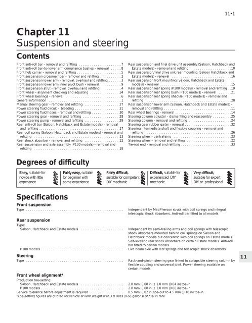
<strong>11</strong>•2 <strong>Suspension</strong> <strong>and</strong> <strong>steering</strong>WheelsType . . . . . . . . . . . . . . . . . . . . . . . . . . . . . . . . . . . . . . . . . . . . . . . . . . . .Size:Saloon, Hatchback <strong>and</strong> Estate models:Steel . . . . . . . . . . . . . . . . . . . . . . . . . . . . . . . . . . . . . . . . . . . . . . . .Alloy . . . . . . . . . . . . . . . . . . . . . . . . . . . . . . . . . . . . . . . . . . . . . . . .P100 models . . . . . . . . . . . . . . . . . . . . . . . . . . . . . . . . . . . . . . . . . . . .Pressed steel or alloy13 x 4.50 in, 13 x 5.50 in, or 14 x 5.50 in14 x 5.50 in14 x 5.50 inTyre sizesNote: Manufacturers often modify tyre sizes <strong>and</strong> pressure recommendations. The following is intended as a guide only. Refer to your vehicleh<strong>and</strong>book or a <strong>Ford</strong> dealer for the latest recommendationsSaloon <strong>and</strong> Hatchback models . . . . . . . . . . . . . . . . . . . . . . . . . . . . . . . 165 R 13H, 165 R 135, 165 R 13T, 185/70 R 13H, 185/70 R 135,185/70 R13T, 195/60 R 14H, 195/60 VR 14 or 195/65 R 14TEstate models . . . . . . . . . . . . . . . . . . . . . . . . . . . . . . . . . . . . . . . . . . . . . 175 R 13H, 175 R 135,175 R 13T, 195/70 R 13H, 195/65 R 14T,195/60 R 14H or 195/60 VR 14 P100 models 185R 14 8PRTyre pressures (cold): lbf/in 2 (bar): Front RearAll Saloon, Hatchback <strong>and</strong> Estate models with normal load* . . . . . . . 26 (1.8) 26 (1.8)All Saloon <strong>and</strong> Hatchback models with full load . . . . . . . . . . . . . . . . 29 (2.0) 36 (2.5)Estate models with full load:175 R 13H, 175 R 135,175 R 13T, 195/70 R 13H <strong>and</strong> 195/65 R14T . 29 (2.0) 48 (2.8)195/60 R 14H <strong>and</strong> 195/60 VR 14 . . . . . . . . . . . . . . . . . . . . . . . . . . 29 (2.0) 36 (2.5)P100 models with light load . . . . . . . . . . . . . . . . . . . . . . . . . . . . . . . . 26 (1.8) 36 (2.5)P100 models with full load . . . . . . . . . . . . . . . . . . . . . . . . . . . . . . . . . 50 (3.5) 65 (4.5)*Normal load is defined as up to three passengers (or equivalent). For sustained high speeds add 1.5 lbf/in 2 (0.1 bar) for every 6 mph (10 km/h)over 100 mph (160 km/h)†A light load is defined as one passenger plus up to 100 kg (220 lb) payloadTorque wrench settings Nm lbf ftRoadwheel nutsWheelnuts:Saloon, Hatchback <strong>and</strong> Estate models (steel <strong>and</strong> alloy wheels) . . . . 70 to 100 52 to 74P100 models . . . . . . . . . . . . . . . . . . . . . . . . . . . . . . . . . . . . . . . . . . . . 85 to 90 63 to 66Hub nuts:Saloon, Hatchback <strong>and</strong> Estate models . . . . . . . . . . . . . . . . . . . . . . . 310 to 350 229 to 258P100 models . . . . . . . . . . . . . . . . . . . . . . . . . . . . . . . . . . . . . . . . . . . . 390 to 450 288 to 332Front suspensionStrut upper mounting nut . . . . . . . . . . . . . . . . . . . . . . . . . . . . . . . . . . . . 40 to 52 30 to 38Hub carrier-to-strut pinch-bolt . . . . . . . . . . . . . . . . . . . . . . . . . . . . . . . . 77 to 92 57 to 68Crossmember-to-underbody bolts . . . . . . . . . . . . . . . . . . . . . . . . . . . . . 70 to 90 52 to 66Engine mounting-to-crossmember nut:Saloon, Hatchback <strong>and</strong> Estate models . . . . . . . . . . . . . . . . . . . . . . . 50 to 70 37 to 52P100 models . . . . . . . . . . . . . . . . . . . . . . . . . . . . . . . . . . . . . . . . . . . . 41 to 58 30 to 43Anti-roll bar-to-lower arm nut . . . . . . . . . . . . . . . . . . . . . . . . . . . . . . . . . 70 to <strong>11</strong>0 52 to 81Anti-roll bar U-clamp-to-underbody bolts . . . . . . . . . . . . . . . . . . . . . . . 55 to 70 41 to 52Lower arm-to-hub carrier balljoint nut . . . . . . . . . . . . . . . . . . . . . . . . . . 65 to 85 48 to 63Lower arm inner pivot bolt:Stage 1 (“clamping”torque) . . . . . . . . . . . . . . . . . . . . . . . . . . . . . . . . . 45 33Loosen fully, then Stage 2 (“snug” torque) . . . . . . . . . . . . . . . . . . . . . 15 <strong>11</strong>Stage 3 . . . . . . . . . . . . . . . . . . . . . . . . . . . . . . . . . . . . . . . . . . . . . . . . Tighten through a further 90ºRear suspensionSaloon, Hatchback <strong>and</strong> Estate models:Lower arm-to-crossmember pivot bolts . . . . . . . . . . . . . . . . . . . . . . . 80 to 95 59 to 70Front guide plate-to-underbody bolts . . . . . . . . . . . . . . . . . . . . . . . . 41 to 51 30 to 38Front guide plate-to-crossmember bolt . . . . . . . . . . . . . . . . . . . . . . . 100 74<strong>Suspension</strong>/final drive unit rear mounting-to-underbody bolts (goldcoloured) . . . . . . . . . . . . . . . . . . . . . . . . . . . . . . . . . . . . . . . . . . . . . 60 44<strong>Suspension</strong>/final drive unit rear mounting-to-final drive unit rear coverbolts . . . . . . . . . . . . . . . . . . . . . . . . . . . . . . . . . . . . . . . . . . . . . . . . 40 to 50 30 to 37Anti-roll bar-to-underbody bracket bolts . . . . . . . . . . . . . . . . . . . . . . 20 to 25 15 to 18Hub carrier/brake backplate-to-lower arm bolts*:Type X . . . . . . . . . . . . . . . . . . . . . . . . . . . . . . . . . . . . . . . . . . . . . . . 52 to 64 38 to 47Type Y . . . . . . . . . . . . . . . . . . . . . . . . . . . . . . . . . . . . . . . . . . . . . . . 80 to 100 59 to 74Hub nut . . . . . . . . . . . . . . . . . . . . . . . . . . . . . . . . . . . . . . . . . . . . . . . . 250 to 290 185 to 214*See Section 15
<strong>Suspension</strong> <strong>and</strong> <strong>steering</strong> <strong>11</strong>•3Torque wrench settings (continued) Nm lbf ftP100 models:Shock absorber-to-chassis crossmember bolt . . . . . . . . . . . . . . . . . . . 60 to 70 44 to 52Leaf spring-to-front bracket bolt . . . . . . . . . . . . . . . . . . . . . . . . . . . . . . 157 to 196 <strong>11</strong>6 to 145Leaf spring-to-spring shackle bolt . . . . . . . . . . . . . . . . . . . . . . . . . . . . . 157 to 196 <strong>11</strong>6 to 145Spring shackle-to-underbody bolt . . . . . . . . . . . . . . . . . . . . . . . . . . . . . 80 to 85 59 to 63Axle-to-leaf spring U-bolt nuts . . . . . . . . . . . . . . . . . . . . . . . . . . . . . . . . 39 to 58 29 to 43Manual <strong>steering</strong>Steering gear-to-crossmember bolts:Stage 1 (“clamping” torque) . . . . . . . . . . . . . . . . . . . . . . . . . . . . . . . . 45 33Loosen fully, then Stage 2 (“snug” torque) . . . . . . . . . . . . . . . . . . . . . 15 <strong>11</strong>Stage 3 . . . . . . . . . . . . . . . . . . . . . . . . . . . . . . . . . . . . . . . . . . . . . . . . Tighten through a further 90ºSteering column adjuster through-bolt . . . . . . . . . . . . . . . . . . . . . . . . . . 6 to 8 4 to 6Tie-rod end locknut . . . . . . . . . . . . . . . . . . . . . . . . . . . . . . . . . . . . . . . 57 to 68 42 to 50Tie-rod end-to-hub carrier nut* . . . . . . . . . . . . . . . . . . . . . . . . . . . . . . . 20 to 32 15 to 24Tie-rod-to-<strong>steering</strong> rack balljoint . . . . . . . . . . . . . . . . . . . . . . . . . . . . . . 72 to 88 53 to 65Steering wheel nut . . . . . . . . . . . . . . . . . . . . . . . . . . . . . . . . . . . . . . . . . 45 to 55 33 to 41Intermediate shaft-to-inner column clamp bolt . . . . . . . . . . . . . . . . . . . 20 to 25 15 to 18Flexible coupling-to-<strong>steering</strong> gear clamp nut . . . . . . . . . . . . . . . . . . . . . 24 to 26 17 to 19Column mounting pinch-bolt . . . . . . . . . . . . . . . . . . . . . . . . . . . . . . . . . 45 to 55 33 to 41Pinion retaining nut . . . . . . . . . . . . . . . . . . . . . . . . . . . . . . . . . . . . . . . . . 70 to 100 52 to 74Slipper plug† . . . . . . . . . . . . . . . . . . . . . . . . . . . . . . . . . . . . . . . . . . . . . . 4 to 5 3 to 4*Tighten nut to specified torque <strong>and</strong> then tighten to next available split pin hole†Tighten nut to specified torque <strong>and</strong> then loosen off 60º to 70ºPower <strong>steering</strong> (where different to manual <strong>steering</strong>)Tie-rod to <strong>steering</strong> rack balljoint . . . . . . . . . . . . . . . . . . . . . . . . . . . . . . . 70 to 77 52 to 57Flexible coupling-to-<strong>steering</strong> gear clamp bolt . . . . . . . . . . . . . . . . . . . . 16 to 20 12 to 15Intermediate shaft-to-inner column clamp bolt . . . . . . . . . . . . . . . . . . . 16 to 20 12 to 15Pinion locknut . . . . . . . . . . . . . . . . . . . . . . . . . . . . . . . . . . . . . . . . . . . . . 37 to 47 27 to 35Slipper plug . . . . . . . . . . . . . . . . . . . . . . . . . . . . . . . . . . . . . . . . . . . . . . . 3 to 4 2 to 3Pump rear support bar nut <strong>and</strong> bolt . . . . . . . . . . . . . . . . . . . . . . . . . . . . 41 to 51 30 to 38Pump mounting bracket-to-engine bolts . . . . . . . . . . . . . . . . . . . . . . . . 52 to 64 38 to 47Pump pulley bolt . . . . . . . . . . . . . . . . . . . . . . . . . . . . . . . . . . . . . . . . . . . 10 to 12 7 to 9Fluid hose-to-pinion housing bolt . . . . . . . . . . . . . . . . . . . . . . . . . . . . . . 21 to 26 15 to 19Fluid pressure hose-to-pump union . . . . . . . . . . . . . . . . . . . . . . . . . . . . 26 to 31 19 to 23Fluid return hose-to-pump union . . . . . . . . . . . . . . . . . . . . . . . . . . . . . . 16 to 20 12 to 151 General informationThe front suspension is of independentMacPherson strut type incorporating coilsprings <strong>and</strong> integral telescopic shockabsorbers. The lower end of each strut isattached to a hub carrier, which carries thewheel hub <strong>and</strong> bearings, <strong>and</strong> the brakeassembly. The lower end of each hub carrieris attached to a suspension lower arm by asealed balljoint. The inboard ends of the lowerarms are attached to the front suspensioncrossmember <strong>and</strong> the lower arms thusprovide lateral location for the strutassemblies. The upper end of each strut isbolted to a suspension turret on the vehiclebody. An anti-roll bar is mounted to the rear ofthe lower arms, <strong>and</strong> resists the roll tendencyof the front suspension.On Saloon, Hatchback <strong>and</strong> Estate models,the rear suspension is also of independenttype, incorporating semi-trailing arms, coilsprings <strong>and</strong> telescopic shock absorbers. Thesemi-trailing arms are attached to thesuspension crossmember at their forwardends, <strong>and</strong> to the hub carriers at the rear. Thecoil springs are located between thesemi-trailing arms <strong>and</strong> the vehicle underbody.On Saloon <strong>and</strong> Hatchback models, the shockabsorbers are mounted behind the coilsprings, but on Estate models they areconcentric with the coil springs. On someEstate models the shock absorbers are of theself-levelling type. The suspensioncrossmember is attached to the vehicleunderbody, <strong>and</strong> to the final drive unit. Certainmodels are fitted with an anti-roll bar which ismounted to the rear of the final drive unit, <strong>and</strong>is attached to the semi-trailing arms byconnecting links.The rear suspension on P100 modelsconsists of a beam axle located <strong>and</strong>supported by a leaf spring on each side, <strong>and</strong>utilizing telescopic shock absorbers to controlvertical movement. The hub <strong>and</strong> brakeassemblies are attached directly to each sideof the axle. The axle is bolted to the leafsprings using U-bolts <strong>and</strong> counterplates, <strong>and</strong>the shock absorbers are attached to thecounterplates at their lower ends <strong>and</strong> thevehicle underbody at their upper ends.The <strong>steering</strong> gear is of the conventionalrack <strong>and</strong> pinion type located ahead of thefront wheels. Movement of the <strong>steering</strong> wheelis transmitted to the <strong>steering</strong> gear by meansof a shaft containing a universal joint. Thefront hub carriers are connected to the<strong>steering</strong> gear by tie-rods, each having an inner<strong>and</strong> outer balljoint. Power-assisted <strong>steering</strong> isavailable on some models, assistance beingprovided hydraulically by an engine-drivenpump.2 Front suspension crossmember- removal <strong>and</strong> refittingRemoval1 Remove the <strong>steering</strong> gear.2 Support the engine with a jack <strong>and</strong>interposed block of wood under the sump.3 Unscrew <strong>and</strong> remove the engine mountingnuts from the top of the mountings in theengine bay (see illustration).4 Raise the engine slightly with the jack, <strong>and</strong>ensure that it is safely supported, <strong>and</strong> justclear of the engine mounting rubbers.5 Unscrew <strong>and</strong> remove the nuts, washers <strong>and</strong>pivot bolts securing the lower arms to thecrossmember, <strong>and</strong> pull the arms from thecrossmember. Note that the pivot bolt headsface to the rear of the vehicle.<strong>11</strong>
<strong>11</strong>•4 <strong>Suspension</strong> <strong>and</strong> <strong>steering</strong>2.3 Engine mounting nut (arrowed)6 Where applicable, remove the brake pipesfrom the clips on the crossmember, takingcare not to strain them, <strong>and</strong> detach any cablesor electrical leads which may be secured withclips or cable-ties, noting their positions.7 Support the crossmember with a jack, thenunscrew <strong>and</strong> remove the four mounting bolts(see illustration).8 Lower the crossmember <strong>and</strong> withdraw itfrom under the vehicle.9 If desired, the engine mountings can nowbe unbolted from the crossmember.Refitting10 Refitting is a reversal of removal, but bearin mind the following points.<strong>11</strong> Do not tighten the lower arm pivot boltsuntil the weight of the vehicle is resting on itswheels. This is to prevent “wind up” of therubber bushes which will occur when thevehicle is lowered if the bolts have beentightened with no load on the suspension. Thefollowing procedure must be used whentightening the pivot bolts. Tighten the bolt tothe specified “clamping” torque, then loosenthe bolt fully. Re-tighten to the specified“snug” torque <strong>and</strong> then further tighten the boltthrough the specified angle.12 Refit any cables or electrical leads in theiroriginal positions, where applicable.13 When lowering the engine onto itsmountings, ensure that the locating pegs onthe mountings engage with the holes in themounting brackets.3 Front suspension lower arm -removal, overhaul <strong>and</strong> refittingNote: A balljoint separator tool will berequired for this operation.Removal1 To improve access, raise the front of thevehicle on ramps. Do not jack the vehicle upat this stage. Apply the h<strong>and</strong>brake.2 Unscrew <strong>and</strong> remove the nut, washer <strong>and</strong>pivot bolt securing the relevant lower arm tothe crossmember (see illustration).3 Remove the anti-roll bar-to-lower armsecuring nut <strong>and</strong> recover the dished washer<strong>and</strong> plastic cover (where applicable) (seeillustration).2.7 Front suspension crossmembermounting bolts (arrowed)4 Ensure that the h<strong>and</strong>brake is applied, jackup the front of the vehicle <strong>and</strong> support on axlest<strong>and</strong>s (see “Jacking <strong>and</strong> Vehicle Support”).5 Remove the split pin <strong>and</strong> unscrew thecastellated nut from the lower arm balljoint.Using a balljoint separator tool, disconnectthe lower arm from the hub carrier. The lowerarm can now be withdrawn from the vehicle.Recover the remaining dished washer <strong>and</strong>plastic cover (where applicable) from the endof the anti-roll bar.Overhaul6 If the lower arm has been removed due to aworn balljoint, the complete arm must berenewed.7 The anti-roll bar compliance bushes can berenewed as described in Section 8, but notethat the bushes on both sides of the vehiclemust be renewed at the same time. The lowerarm inner pivot bush can be renewed asdescribed in Section 9.Refitting8 To refit the lower arm, proceed as follows.9 Fit the shallow dished washer (colourcoded black or green) <strong>and</strong> the plastic cover(where applicable) to the end of the anti-rollbar, then refit the lower arm to the anti-rollbar. Fit the remaining plastic cover (whereapplicable) <strong>and</strong> the deep dished washer(colour coded yellow or black) <strong>and</strong> refit thesecuring nut. Do not tighten the nut at thisstage. Note that the convex faces of thedished washers must face the lower arm.3.2 Front suspension lower arm-tocrossmemberpivot bolt <strong>and</strong> nut10 Reconnect the balljoint to the hub carrier,refit the castellated nut <strong>and</strong> tighten to thespecified torque. Fit a new split pin.<strong>11</strong> Locate the end of the lower arm in thecrossmember <strong>and</strong> refit the pivot bolt, washer<strong>and</strong> nut. If necessary, push the outer rim ofthe roadwheel in order to line up the holes inthe lower arm bush <strong>and</strong> the crossmember.Note that the pivot bolt head should face tothe rear of the vehicle. Do not tighten the boltat this stage.12 Lower the vehicle so that its weight isresting on the roadwheels, <strong>and</strong> bounce thevehicle to settle the suspension.13 Tighten the lower arm pivot bolt, followingthe procedure given in Section 2.14 Tighten the anti-roll bar-to-lower armsecuring nut to the specified torque.15 Lower the vehicle from the ramps, if notalready done.4 Front suspension strut -removal, overhaul <strong>and</strong> refittingNote: A spring compressor tool will berequired if the strut is to be dismantled.Removal1 Loosen the relevant front roadwheel nuts,apply the h<strong>and</strong>brake, jack up the front of thevehicle <strong>and</strong> support on axle st<strong>and</strong>s (see“Jacking <strong>and</strong> Vehicle Support”).2 Remove the roadwheel. On P100 modelsmark the position of the roadwheel in relationto one of the wheel studs before removal.3 Remove the front brake caliper but do notdisconnect the hydraulic hose. Support thecaliper on an axle st<strong>and</strong> to avoid straining thehose.4 Where applicable, unbolt the ABS wheelsensor from the hub carrier <strong>and</strong> detach thewire from the clip on the strut. Unplug theconnector <strong>and</strong> place the sensor to one side.5 Unscrew <strong>and</strong> remove the pinch-bolt whichsecures the hub carrier to the strut. Using asuitable lever, such as a cold chisel, lever thehub carrier clamp legs <strong>and</strong> wedge them apart.6 Lever the suspension lower armdownwards to separate the hub carrier fromthe bottom of the strut.3.3 Front anti-roll bar-to-lower armsecuring nut (arrowed)
<strong>Suspension</strong> <strong>and</strong> <strong>steering</strong> <strong>11</strong>•55 Front hub carrier - removal <strong>and</strong>refitting4.7 Hold the strut piston rod with a 6 mmAllen key when unscrewing the uppermounting nut7 Working in the engine compartment,unscrew the strut upper mounting nut, at thesame time supporting the strut from below.Use a 6 mm Allen key inserted in the end ofthe strut piston rod to prevent the rod fromturning as the upper mounting nut isunscrewed (see illustration). On somemodels, the upper mounting nut may be fittedwith a plastic cover. Note the upper mountingcup under the nut.8 Withdraw the strut from under the wing ofthe vehicle.Overhaul9 To dismantle the strut, proceed as follows.10 Using spring compressors, compress thecoil spring. Do not attempt to compress thespring without using purpose-made springcompressors, as the spring is underconsiderable tension, <strong>and</strong> personal injury mayoccur if it is suddenly released (seeillustration).<strong>11</strong> Hold the piston rod as described inparagraph 7, unscrew the nut from the piston4.10 <strong>Suspension</strong> strut fitted with springcompressorsrod <strong>and</strong> remove the lower cup, bearing, springseat, gaiter, coil spring <strong>and</strong> bump stop (seeillustration).12 Working in the engine compartment,remove the upper cup <strong>and</strong> nylon spacer, <strong>and</strong>if required prise out the rubber insulator.13 Clean all the components <strong>and</strong> examinethem for wear <strong>and</strong> damage. Check the actionof the shock absorber by mounting it verticallyin a vice <strong>and</strong> operating the piston rod severaltimes through its full stroke. If any unevenresistance is evident, the shock absorbermust be renewed. Renew any worn ordamaged components as applicable.Refitting14 Reassembly <strong>and</strong> refitting is a reversal ofdismantling <strong>and</strong> removal, bearing in mind thefollowing points.15 When reassembling, ensure that the gaiteris fitted over the bump stop, <strong>and</strong> that the endsof the coil spring are correctly located on thespring seats. Also ensure that the bearing iscorrectly located on the upper spring seat.16 Fit the nylon spacer over the piston rodbefore fitting the strut to the top mounting.17 Tighten all fixings to the specified torque.18 On P100 models align the previouslymade marks on the roadwheel <strong>and</strong> wheelstud.Note: A balljoint separator tool will berequired for this operation.Removal1 Loosen the relevant front roadwheel nuts,apply the h<strong>and</strong>brake, jack up the front of thevehicle <strong>and</strong> support on axle st<strong>and</strong>s (see“Jacking <strong>and</strong> Vehicle Support”).2 Remove the roadwheel. On P100 modelsmark the position of the roadwheel in relationto one of the wheel studs before removal.3 Remove the front brake caliper but do notdisconnect the hydraulic hose. Support thecaliper on an axle st<strong>and</strong>, or suspend it with wirefrom the coil spring to avoid straining the hose.4 Mark the position of the brake disc inrelation to the drive flange, <strong>and</strong> on Saloon,Hatchback <strong>and</strong> Estate models, remove theretaining screw or spire washer(s), asapplicable, <strong>and</strong> remove the disc. On P100models, unscrew the five retaining nuts <strong>and</strong>remove the wheel adapter plate <strong>and</strong> disc.5 Where applicable, unbolt the ABS wheelsensor from the hub carrier <strong>and</strong> unplug thewiring connector. Place the sensor to one side.6 Remove the split pin <strong>and</strong> unscrew thecastellated nut securing the tie-rod end to thehub carrier. Using a balljoint separator tool,disconnect the tie-rod end from the hub carrier.7 Repeat the procedure given in the previousparagraph for the lower arm-to-hub carrierballjoint.8 Unscrew <strong>and</strong> remove the pinch-bolt whichsecures the hub carrier to the strut (seeillustration). Using a suitable lever, such as acold chisel, lever the hub carrier clamp legs<strong>and</strong> wedge them apart. Withdraw the hubcarrier from the strut.Refitting9 Refitting is a reversal of removal, but usenew split pins on the castellated nuts, <strong>and</strong>align the previously made marks on the brakedisc <strong>and</strong> hub. Tighten all fixings to thespecified torque.10 On P100 models align the previouslymade marks on the roadwheel <strong>and</strong> wheelstud.<strong>11</strong>4.<strong>11</strong> Cross-section of the front strut upper mountingA BearingB Nylon spacerC Upper cupD Rubber insulatorE Lower cupF Spring seatG Bump stopH Gaiter5.8 Unscrewing the hub carrier-to-strutpinch-bolt
<strong>11</strong>•6 <strong>Suspension</strong> <strong>and</strong> <strong>steering</strong>6.2 Front hub carrier mounted in vice tounscrew hub nut6.4 Front hub components6 Front wheel bearings - renewalA Dust capB Hub nutC Splined washerD Taper roller bearingE Bearing outer raceF Hub carrierG Oil sealH Drive flange1 Remove the hub carrier.2 Reverse the roadwheel nuts <strong>and</strong> screwthem fully onto the studs to protect thethreads, then mount the hub carrier assemblyin a vice as shown (see illustration).3 Prise the dust cap from the rear of the hubcarrier, <strong>and</strong> unscrew the hub nut with asuitable socket. Note that on all modelsmanufactured before late December 1982,both left <strong>and</strong> right-h<strong>and</strong> nuts have aright-h<strong>and</strong> thread, but as from this date,left-h<strong>and</strong> thread assemblies wereprogressively fitted to the right-h<strong>and</strong> hubcarrier. The modified right-h<strong>and</strong> hub can beidentified by the letter “R” stamped on itsouter face, or by the colour of the hub nutnylon insert, blue indicates a normalright-h<strong>and</strong> thread, <strong>and</strong> yellow indicates aleft-h<strong>and</strong> thread.4 Remove the splined washer, <strong>and</strong> tap thehub carrier from the drive flange. Recover thebearing inner race <strong>and</strong> rollers from the innerend of the hub carrier (see illustration).5 Prise the oil seal from the outer end of thehub carrier <strong>and</strong> remove the remaining bearinginner race <strong>and</strong> rollers.6 Using a soft metal drift, drive the bearingouter races from the hub carrier, taking carenot to damage the inner surface of the carrier.7 Clean the hub carrier <strong>and</strong> drive flange withparaffin, wipe dry <strong>and</strong> examine for damage<strong>and</strong> wear. Note that the components aremachined to very close tolerances, <strong>and</strong> thebearings are supplied in matched pairs,therefore scrupulous cleanliness must beobserved.8 Using a metal tube of suitable diameter,drive the new bearing outer races fully into thehub carrier. Ensure that the races are seatedcorrectly.9 Pack the inner bearing races <strong>and</strong> rollerswith high-melting-point lithium-based grease,<strong>and</strong> locate the outer bearing assembly in thehub camber.10 Fill the cavities between the sealing lips ofthe oil seal with grease, then drive it fully intothe hub carrier using a block of wood or ametal tube of suitable diameter. Note that onearly models the oil seal has a rubber casing,<strong>and</strong> this early type of seal should be replacedwith the later type which has a metal casing.The oil seal should be renewed regardless oftype, <strong>and</strong> a new seal of the correct type isnormally supplied with the new wheel bearings.<strong>11</strong> With the drive flange mounted in a vice, asduring dismantling, tap the hub carrier ontothe drive flange.12 Fit the inner bearing assembly, tapping itinto place with a metal tube of suitablediameter if necessary, <strong>and</strong> fit the splinedwasher. Note that the bearings are self-settingon assembly, <strong>and</strong> no subsequent adjustmentis required.13 Refit the hub nut <strong>and</strong> tighten it to thespecified torque.14 Tap the dust cap into position in the hubcarrier.15 Remove the assembly from the vice,remove the roadwheel nuts, <strong>and</strong> refit the hubcarrier.7 Front anti-roll bar - removal<strong>and</strong> refittingRemoval1 To improve access, raise the front of thevehicle on ramps. Do not jack the vehicle upat this stage. Apply the h<strong>and</strong>brake.7.2a Bend back the locktabs (arrowed) . . .2 Where applicable bend back the locktabs,then unscrew the two bolts securing each ofthe two anti-roll bar U-clamps to the vehicleunderbody (see illustrations).3 Ensure that the h<strong>and</strong>brake is applied, jackup the front of the vehicle <strong>and</strong> support on axlest<strong>and</strong>s (see “Jacking <strong>and</strong> Vehicle Support”).4 Remove the anti-roll bar-to-lower armsecuring nuts <strong>and</strong> recover the dished washers<strong>and</strong> plastic covers, where applicable (seeillustration).5 Unscrew <strong>and</strong> remove the nut, washer <strong>and</strong>pivot bolt securing one of the lower arms tothe crossmember, <strong>and</strong> pull the end of thelower arm from the crossmember.6 Pull the anti-roll bar from the bush in the“free” lower arm then slide the anti-roll barfrom the remaining fixed lower arm. Recoverthe remaining dished washers <strong>and</strong> plasticcovers (where applicable) from the ends of theanti-roll bar.7 If necessary, the anti-roll bar compliancebushes can be renewed as described inSection 8, <strong>and</strong> the anti-roll bar U-clampbushes can be renewed by sliding them offthe ends of the bar. Note that although theU-clamp bushes are of a split design, theyshould not be levered open to aid fitting, <strong>and</strong>the new bushes must be slid on from the endsof the anti-roll bar. The bushes should alwaysbe renewed in pairs.7.2b . . . unscrew the bolts <strong>and</strong> remove theanti-roll bar U-clamps
<strong>Suspension</strong> <strong>and</strong> <strong>steering</strong> <strong>11</strong>•7Refitting8 To refit the anti-roll bar, proceed as follows.9 Fit the shallow dished washers (colourcoded black or green) <strong>and</strong> the plastic covers(where applicable) to the ends of the anti-rollbar, then push the anti-roll bar through thebushes in the lower arms. Fit the remainingplastic covers (where applicable) <strong>and</strong> thedeep dished washers (colour coded yellow orblack) <strong>and</strong> loosely fit the securing nuts. Notethat the convex faces of the dished washersmust face the lower arm. Do not tighten thenuts fully at this stage.10 Locate the “free” lower arm inner pivotbush in the crossmember, <strong>and</strong> refit the pivotbolt, washer <strong>and</strong> nut. If necessary, push theouter rim of the roadwheel in order to line upthe holes in the lower arm bush <strong>and</strong> thecrossmember. Note that the pivot bolt headshould face to the rear of the vehicle. Do nottighten the bolt at this stage.<strong>11</strong> Lower the vehicle so that its weight isresting on the roadwheels.12 Refit the anti-roll bar U-clamps to thevehicle underbody. Note that various differenttypes of clamping components have beenused during production, <strong>and</strong> if any of thecomponents are to be renewed, it is importantto retain the old components for identificationwhen ordering new parts. The same type ofclamp assembly must be used on both sidesof the vehicle. Tighten the bolts evenly oneach clamp to the specified torque. Whereapplicable, secure the bolts with the locktabs.13 Bounce the vehicle to settle thesuspension, then tighten the lower arm pivotbolt, following the procedure given in Section 2.14 Tighten the anti-roll bar-to-lower armsecuring nuts to the specified torque.15 Lower the vehicle from the ramps, if notalready done.7.4 Front anti-roll bar-to-lower arm mountingA Rear (black or green) shallow dishedwasherB Plastic cover (where applicable)C Compliance bushesD Plastic cover (where applicable)E Front (yellow or black) deep dishedwasher8 Front anti-roll bar-to-lower armcompliance bushes - renewalNote: The compliance bushes must berenewed in vehicle sets, therefore the busheson both sides of the vehicle must be renewedat the same time. If plastic covers were notoriginally fitted between the dished washers<strong>and</strong> the bushes, suitable covers should beobtained for fitting during reassembly.1 Remove the anti-roll bar.2 Using a thin-bladed chisel or screwdriver,carefully prise out the compliance bushesfrom the lower arms.3 Tap the new bushes into place using asuitable socket or tube drift (see illustration).4 Some vehicles may have small rubberspacer washers fitted to the ends of theanti-roll bar, <strong>and</strong> these should be discardedon reassembly.5 Refit the anti-roll bar.9 Front suspension lower arminner pivot bush - renewal1 To improve access, raise the front of thevehicle on ramps. Apply the h<strong>and</strong>brake.2 Unscrew <strong>and</strong> remove the nut, washer <strong>and</strong>pivot bolt securing the relevant lower arm tothe crossmember.3 Remove the anti-roll bar-to-lower armsecuring nut <strong>and</strong> recover the dished washer<strong>and</strong> plastic cover (where applicable).4 Ensure that the h<strong>and</strong>brake is applied, jackup the front of the vehicle <strong>and</strong> support on axlest<strong>and</strong>s (see “Jacking <strong>and</strong> Vehicle Support”).5 Pull the inner end of the lower arm from thecrossmember.6 The pivot bush can now be removed fromthe lower arm using a long bolt with nut,washers <strong>and</strong> a suitable metal tube.7 Lubricate the new bush with soapy water,<strong>and</strong> fit with a single continuous action to avoiddeformation of the bush, again using the bolt,nut, washers <strong>and</strong> tube.8 Locate the end of the lower arm in thecrossmember, <strong>and</strong> refit the pivot bolt, washer<strong>and</strong> nut. If necessary, push the outer rim ofthe roadwheel in order to line up the holes inthe lower arm bush <strong>and</strong> the crossmember.Note that the pivot bolt head should face tothe rear of the vehicle. Do not tighten the boltat this stage.9 Refit the plastic cover, dished washer(where applicable), <strong>and</strong> nut to the end of theanti-roll bar. Do not tighten the nut at thisstage.10 Lower the vehicle so that its weight isresting on the roadwheels, <strong>and</strong> bounce thevehicle to settle the suspension.<strong>11</strong> Tighten the lower arm pivot bolt, followingthe procedure given in Section 2.12 Tighten the anti-roll bar-to-lower armsecuring nut to the specified torque.13 Lower the vehicle from the ramps, if notalready done.10 Rear suspension <strong>and</strong> finaldrive unit assembly (Saloon,Hatchback <strong>and</strong> Estatemodels) - removal <strong>and</strong> refittingNote: From May 1986, revised final drive unitrear mounting bolts have been used inproduction. Whenever the earlier type of boltsare removed, they should be discarded <strong>and</strong>the later type fitted. The earlier bolts arecoloured blue, <strong>and</strong> the later type bolts arecoloured gold.Removal1 Jack up the vehicle <strong>and</strong> support on axlest<strong>and</strong>s (see “Jacking <strong>and</strong> Vehicle Support”). Itis only strictly necessary to jack up the rear ofthe vehicle, but this provides only limitedaccess. Note that the axle st<strong>and</strong>s should bepositioned under the side members.2 Remove the rear section of the exhaustsystem - ie. from the joint.3 Remove the propeller shaft.4 Disconnect the h<strong>and</strong>brake equaliser fromthe operating rod by removing the circlip <strong>and</strong>8.3 Tapping a front anti-roll bar-to-lowerarm compliance bush into position<strong>11</strong>
<strong>Suspension</strong> <strong>and</strong> <strong>steering</strong> <strong>11</strong>•9<strong>11</strong>.10 Rear suspension front guide plate<strong>11</strong>.12 Lower arm-to-crossmember innerpivot<strong>11</strong>.23 Rear suspension lower arm brakepipe brackets (arrowed)A Left-h<strong>and</strong> bracket B Right-h<strong>and</strong> bracketRefitting15 Refitting is a reversal of removal, bearingin mind the following points.16 Where applicable, secure the larger frontguide plate bolt by bending up the lockwashertab(s).17 Before tightening the lowerarm-to-crossmember pivot bolts <strong>and</strong> nuts,lower the vehicle so that its weight is restingon the roadwheels, <strong>and</strong> bounce the vehicle tosettle the suspension. Ensure that the boltsare orientated as noted during removal.18 On completion, bleed the brakes <strong>and</strong>adjust the h<strong>and</strong>brake.Models with rear disc brakesNote: A suitable puller will be required toremove the drive flange, <strong>and</strong> a new rear hubnut must be used on reassembly.Removal19 With the vehicle resting on its wheels,loosen the rear hub nut. A suitable extensionbar will be required, as the nut is extremelytight. Note that the left-h<strong>and</strong> nut has aleft-h<strong>and</strong> thread, ie it is undone in a clockwisedirection. Before loosening the nut, ensurethat the h<strong>and</strong>brake is applied, <strong>and</strong> chock therelevant rear wheel.20 Loosen the rear roadwheel nuts on theside concerned, chock the front wheels, jackup the rear of the car <strong>and</strong> support on axlest<strong>and</strong>s placed under the side members.21 Remove the rear roadwheel.22 Remove the rear section of the exhaustsystem - ie from the joint.23 Unscrew the brake pipe from the brakehose at the bracket on the lower arm (seeillustration). Plug the ends of the pipe <strong>and</strong>hose to prevent leakage <strong>and</strong> dirt ingress, thendetach the hose from the bracket by removingthe U-shaped retaining clip.24 Remove the h<strong>and</strong>brake cable from theclip on the lower arm.25 Unbolt the brake caliper <strong>and</strong> tie it to oneside, taking care not to strain the brake hose.26 Mark the position of the brake disc inrelation to the hub, remove the retaining spirewasher(s), <strong>and</strong> remove the disc.27 Disconnect the driveshaft from the hubassembly by unscrewing the six securingbolts. Support the driveshaft to avoid strainingthe joints, or alternatively, unbolt it from thefinal drive unit at the inboard end <strong>and</strong> removethe driveshaft from the vehicle. At all times,avoid bending the driveshaft joints toexcessive angles, <strong>and</strong> do not allow the shaftto hang down from one end.28 Unscrew <strong>and</strong> remove the rear hub nut,<strong>and</strong> using a puller pull off the drive flange.29 Unscrew the four bolts securing the hubcarrier <strong>and</strong> splash shield to the lower arm.Remove the hub carrier <strong>and</strong> splash shield.Note that the stub axle is retained in the hubcarrier.30 Disconnect the ABS sensor, <strong>and</strong> detachthe lead from the clip on the lower arm.31 Remove the propeller shaft.32 Proceed as shown in paragraphs 7 to 14inclusive.Refitting33 Refitting is a reversal of removal, bearingin mind the following points.34 Where applicable, secure the larger frontguide plate bolt by bending up the lockwashertabs.35 When refitting the hub carrier to the lowerarm note that there are two types of bolts used. The two types of bolt must not be mixed on avehicle, but can be changed in complete setsfor the alternative type. A complete set is eightbolts, four each side. Note that the two typesof bolt have different torque wrench settings.When renewing the wheel bearings a suitablepuller will be required to remove the driveflange, <strong>and</strong> a new rear hub nut must be usedon reassembly.12.1 Rear shock absorber lower mounting- Saloon <strong>and</strong> Hatchback models36 When refitting the drive flange to the hubassembly, use a new hub nut, <strong>and</strong> leavetightening until the vehicle is resting on itswheels. Apply the h<strong>and</strong>brake <strong>and</strong> chock therelevant rear wheel when tightening the nut.37 When refitting the brake disc, align thepreviously made marks on disc <strong>and</strong> hub.38 Before tightening the lowerarm-to-crossmember pivot bolts <strong>and</strong> nuts,lower the vehicle so that its weight is restingon the roadwheels, <strong>and</strong> bounce the vehicle tosettle the suspension. Ensure that the boltsare orientated as noted during removal.39 On completion, bleed the brakes <strong>and</strong>adjust the h<strong>and</strong>brake.12 Rear shock absorber -removal <strong>and</strong> refittingSaloon <strong>and</strong> Hatchback models1 With the weight of the vehicle resting on theroadwheels, work under the vehicle tounscrew <strong>and</strong> remove the shock absorberlower mounting bolt <strong>and</strong> nut from the relevantlower arm (see illustration). If desired, therear of the vehicle can be raised on ramps toimprove access.2 Working inside the rear of the vehicle,remove the trim cover behind the sidecushion. The cover is secured by twoself-tapping screws (see illustrations).12.2a Remove the trim cover . . .<strong>11</strong>
<strong>Suspension</strong> <strong>and</strong> <strong>steering</strong> <strong>11</strong>•<strong>11</strong>nuts, <strong>and</strong> it is important to note that wherethis type of nut is fitted, the left-h<strong>and</strong> nut hasa left-h<strong>and</strong> thread, ie. it is undone in aclockwise direction. Before loosening the nut,ensure that the h<strong>and</strong>brake is applied, <strong>and</strong>chock the relevant rear wheel. A suitableextension bar will be required, as the nut isextremely tight.2 Loosen the rear roadwheel nuts on the sideconcerned, chock the front wheels, <strong>and</strong> jackup the rear of the vehicle <strong>and</strong> support on axlest<strong>and</strong>s (see “Jacking <strong>and</strong> Vehicle Support”).Remove the rear roadwheel.3 Remove the brake drum retaining spirewasher(s) from the wheel stud(s) <strong>and</strong> removethe brake drum. Ensure that the h<strong>and</strong>brake isreleased before removing the brake drum,otherwise the drum will be held in place by theclamping action of the brake shoes.4 Remove the two nylon fasteners, <strong>and</strong>remove the plastic shield from the rear of thebrake backplate (see illustration).5 Unscrew <strong>and</strong> remove the rear hub nut.6 Using a suitable puller, pull the drive flangefrom the end of the driveshaft (seeillustration).7 Unscrew <strong>and</strong> remove the four boltssecuring the hub carrier <strong>and</strong> brake backplateto the lower arm (see illustration). Removethe hub carrier, whilst supporting thedriveshaft. Support the driveshaft by placingaxle st<strong>and</strong>s underneath it, or by securing withstring to the underbody. Note that thedriveshaft joints should not be allowed todeflect through an angle exceeding 13º.8 Refit the brake backplate with the foursecuring bolts to avoid straining the brakepipe.9 With the hub carrier removed, the bearingscan be renewed as follows (see illustration).10 Prise the inner <strong>and</strong> outer oil seals from thehub carrier using a suitable screwdriver, <strong>and</strong>withdraw the taper roller bearings.<strong>11</strong> Using a soft metal drift, drive the bearingouter races from the hub carrier, taking carenot to damage the inner surface of the carrier.14.4 Remove the nylon fasteners (arrowed)to free the plastic shield from the brakebackplate12 Clean the hub carrier <strong>and</strong> drive flange withparaffin, wipe dry <strong>and</strong> examine for damage<strong>and</strong> wear. Note that the components aremachined to very close tolerances, <strong>and</strong> thebearings are supplied in matched pairs,therefore scrupulous cleanliness must beobserved.13 Using a metal tube of suitable diameter,drive the new bearing outer races fully into thehub carrier. Ensure that the races are seatedcorrectly.14 Pack the inner bearing races <strong>and</strong> rollerswith high-melting-point lithium-based grease,<strong>and</strong> locate the outer bearing assembly in thehub carrier.15 Fill the cavities between the sealing lips ofthe oil seal with grease, then drive it fully intothe hub carrier using a block of wood or ametal tube of suitable diameter. Note than onearly models the oil seal has a rubber casing,<strong>and</strong> this type of seal should be replaced withthe later type which has a metal casing. Theoil seal should be renewed regardless of type,<strong>and</strong> a new oil seal of the correct type isnormally supplied with the new wheelbearings.16 Repeat the procedure shown inparagraphs 14 <strong>and</strong> 15 for the outer bearing<strong>and</strong> oil seal.14.6 Pull the drive flange from the end ofthe driveshaft17 Fit the drive flange to the hub carrier inorder to centralise the bearings, then removethe securing bolts from the brake backplate,<strong>and</strong> using a soft-faced mallet, drive the driveflange/hub carrier assembly onto the end ofthe driveshaft.18 Further refitting is a reversal of removal,bearing in mind the following points.19 Refit the hub carrier/brakebackplate-to-lower arm securing bolts withreference to the note at the beginning of thissub-Section.20 Fit a new rear hub nut of the correct type,<strong>and</strong> tighten it with the vehicle resting on itsroadwheels. Apply the h<strong>and</strong>brake <strong>and</strong> chockthe relevant rear wheel. If a staked type nut isused, lock the nut by staking its outer ring intothe groove in the driveshaft.With rear disc brakesNote: See note.at the beginning of this Section21 Loosen the rear hub nut with the vehicleresting on its wheels. Note that the left-h<strong>and</strong>nut has a left-h<strong>and</strong> thread, ie. it is undone in aclockwise direction. Before loosening the nut,ensure that the h<strong>and</strong>brake is applied, <strong>and</strong>chock the relevant rear wheel. A suitableextension bar will be required, as the nut isextremely tight.<strong>11</strong>14.7 Rear hub carrier/brake backplate-to-lower arm securingbolts14.9 Rear hub carrier components - Saloon, Hatchback <strong>and</strong>Estate modelsA Outer oil sealB Outer bearingC Hub carrierD Inner bearingE Inner oil seal
<strong>11</strong>•12 <strong>Suspension</strong> <strong>and</strong> <strong>steering</strong>22 Loosen the rear roadwheel nuts on theside concerned, chock the front wheels, <strong>and</strong>jack up the rear of the vehicle <strong>and</strong> support onaxle st<strong>and</strong>s. Remove the roadwheel <strong>and</strong>release the h<strong>and</strong>brake.23 Unbolt the brake caliper carrier bracket<strong>and</strong> support the caliper on an axle st<strong>and</strong>,taking care not to strain the flexible hose.24 Mark the position of the brake disc inrelation to the drive flange, remove theretaining spire washer(s), <strong>and</strong> remove the disc.25 Unscrew <strong>and</strong> remove the rear hub nut,<strong>and</strong> using a puller, pull off the drive flange.26 Unscrew the four bolts securing the hubcarrier <strong>and</strong> splash shield to the lower arm.Remove the hub carrier <strong>and</strong> splash shield,whilst supporting the driveshaft. Support thedriveshaft by placing axle st<strong>and</strong>s underneathit, or by securing with string to the underbody.Avoid bending the driveshaft joints toexcessive angles, <strong>and</strong> do not allow the shaftto hang down from one end.27 With the hub carrier removed, thebearings can be renewed as described inparagraphs 10 to 16 of this Section.28 Fit the drive flange to the hub carrier inorder to centralise the bearings, then using asoft-faced mallet, drive the drive flange/hubcarrier assembly onto the end of the stub axle.Do not forget to fit the splash shield.29 Further refitting is a reversal of removal,bearing in mind the following points.30 Refit the hub carrier/splashshield-to-lower arm securing bolts withreference to the note at the beginning of thissub-Section.31 When refitting the brake disc, align thepreviously made marks on disc <strong>and</strong> driveflange.32 Fit a new rear hub nut of the correct type,<strong>and</strong> tighten it with the vehicle resting on itsroadwheels. Apply the h<strong>and</strong>brake <strong>and</strong> chockthe relevant rear wheel.P100 modelsNote: A new rear hub nut must be used onreassembly.33 Remove the relevant driveshaft.34 Relieve the staking on the rear hub nut,<strong>and</strong> using a 50 mm socket <strong>and</strong> an extensionbar, unscrew the nut. Note that the nut isextremely tight.35 Pull off the hub, <strong>and</strong> remove the O-ring<strong>and</strong> spacer sleeve from the recess in the hub(see illustration).36 Prise the oil seal from the rear of the hubusing a screwdriver.37 Using a block of wood, or a suitable metaltube inserted from the rear of the hub, tap outthe ball-bearing.38 Clean the hub with paraffin, wipe dry <strong>and</strong>examine for damage <strong>and</strong> wear.39 Using a metal tube of suitable diameter,resting on the bearing outer race only, tap thenew bearing into the hub. Ensure that thebearing is correctly seated.40 Carefully fit a new oil seal to the rear of thehub, using a suitable metal tube.A Oil sealB HubC Ball-bearingD Hub nutE Spacer sleeveF O-ring41 Refitting is a reversal of removal, bearingin mind the following points.42 Fit a new rear hub nut, <strong>and</strong> stake inposition after tightening to the specifiedtorque.15 Rear suspension frontmounting (Saloon, Hatchback<strong>and</strong> Estate models) - renewal1 Chock the front wheels, jack up the rear ofthe vehicle <strong>and</strong> support on axle st<strong>and</strong>s placedunder the side members.2 Unscrew <strong>and</strong> remove the three boltssecuring the relevant front guide plate to theunderbody <strong>and</strong> the suspension crossmember.Where applicable, bend back the lockwashertab(s) on the larger bolt.3 Using a length of wood, lever thesuspension crossmember downwards a fewinches from the underbody, <strong>and</strong> insert thewood as a wedge.4 Using a tool similar to the <strong>Ford</strong> special toolshown (see illustration), or a long bolt withnut, washers <strong>and</strong> a suitable metal tube, pullthe mounting rubber from the crossmember.5 Lubricate the new mounting rubber withsoapy water, <strong>and</strong> use the tool described in theprevious paragraph to press the rubber intothe crossmember.6 Further refitting is a reversal of removal.Where applicable, secure the larger frontguide plate bolt by bending up the lockwashertab(s).15.4 <strong>Ford</strong> special tool 15-014 for removingrear suspension front mounting rubber14.35 Rear hub components - P100 models16 Rear suspension/final driveunit rear mounting (Saloon,Hatchback <strong>and</strong> Estatemodels) - renewalNote: From May 1986, revised rearsuspension/final drive unit rear mounting boltshave been used in production. Whenever theearlier type of bolts are removed, they shouldbe discarded <strong>and</strong> the later type fitted. Theearlier bolts are coloured blue, <strong>and</strong> the latertype bolts are coloured gold.1 Chock the front wheels, jack up the rear ofthe vehicle <strong>and</strong> support on axle st<strong>and</strong>s placedunder the side members.2 Support the final drive unit with a jack,using an interposed block of wood to spreadthe load.3 Unscrew <strong>and</strong> remove the four boltssecuring the mounting to the underbody. Notethe location <strong>and</strong> number of any shims whichmay be fitted.4 Lower the final drive unit sufficiently toenable the mounting to be unbolted from thefinal drive unit rear cover (see illustration).16.4 Rear suspension/final drive unit rearmounting-to-final drive unit rear coverbolts
<strong>Suspension</strong> <strong>and</strong> <strong>steering</strong> <strong>11</strong>•135 Refitting is a reversal of removal, withreference to the note at the beginning of thisSection. Refit any shims in their original notedpositions, <strong>and</strong> tighten all bolts to the specifiedtorque.17 Rear anti-roll bar (Saloon,Hatchback <strong>and</strong> Estatemodels) - removal <strong>and</strong> refittingRemoval1 Loosen the rear roadwheel nuts, chock thefront wheels, jack up the rear of the vehicle<strong>and</strong> support on axle st<strong>and</strong>s placed under theside members.2 Prise off the straps which connect theanti-roll bar to the suspension lower arms(see illustration).3 Unbolt the two securing brackets from theunderbody, <strong>and</strong> remove the anti-roll bar (seeillustration).4 The connecting straps can be prised fromthe ends of the anti-roll bar, <strong>and</strong> theunderbody mounting brackets <strong>and</strong> rubbers,which are of a split design, can be pulled off.5 When fitting new mounting components,lubricate the rubber parts with soapy water toease assembly.Refitting6 Refitting is a reversal of removal. Tightenthe anti-roll bar-to-underbody securing boltsto the specified torque.18 Rear suspension <strong>and</strong> axleassembly (P100 models) -removal <strong>and</strong> refittingNote: All self-locking nuts <strong>and</strong> spring washersmust be renewed on reassembly.Removal1 Chock the front wheels, jack up the rear ofthe vehicle <strong>and</strong> support on axle st<strong>and</strong>s placedunder the side members. Note that a loadedvehicle must not be jacked under thedifferential casing.17.2 Anti-roll bar-to-lower arm connectingstrap2 Support the rear axle with a jack, using aninterposed block of wood to spread the load.3 Remove the propeller shaft.4 Remove the securing circlip <strong>and</strong> the pivotpin, <strong>and</strong> detach the h<strong>and</strong>brake equaliser fromthe linkage on the underbody.5 Remove the h<strong>and</strong>brake cables from theclips on the underbody, <strong>and</strong> from the bracketson the crossmember. To remove the cablesfrom the crossmember, remove the U-shapedretaining clips. Note that the cable adjuster issecured to the right-h<strong>and</strong> crossmemberbracket. Ensure that the h<strong>and</strong>brake isreleased before attempting to disconnect anypart of the mechanism.6 Unscrew the brake pipe from the brakehose on the right-h<strong>and</strong> side of the chassiscrossmember. Plug the ends of the pipe <strong>and</strong>hose to prevent leakage <strong>and</strong> dirt ingress, thendetach the hose from the crossmember byremoving the U-shaped retaining clip (seeillustration).7 Remove the spring clip <strong>and</strong> clevis pin <strong>and</strong>disconnect the spring from the brake loadapportioning valve lever on the right-h<strong>and</strong>side of the underbody (see illustration).8 Detach the exhaust system from the tworear mountings.9 Unbolt the shock absorbers from thechassis crossmember.10 Unbolt the leaf springs from the frontbrackets on the underbody, (Section 19).<strong>11</strong> Lower the rear axle.12 Loosen the spring shackle-to-underbodybolts, then unbolt the leaf springs from thespring shackles, <strong>and</strong> remove the rearsuspension <strong>and</strong> axle assembly from under the17.3 Anti-roll bar-to-underbody securingbracketvehicle, guiding the h<strong>and</strong>brake cables overthe exhaust system.Refitting13 Refitting is a reversal of removal, bearingin mind the following points.14 Do not fully tighten the leaf springmounting bolts or the springshackle-to-underbody bolts until the weight ofthe vehicle is resting on the roadwheels.15 Renew all self-locking nuts <strong>and</strong> springwashers.16 On completion, check the brake loadapportioning valve adjustment <strong>and</strong> theh<strong>and</strong>brake adjustment. Bleed the rear brakecircuit <strong>and</strong> check the axle oil level.19 Rear suspension leaf spring(P100 models) - removal <strong>and</strong>refittingNote: All self-locking nuts <strong>and</strong> spring washersmust be renewed on reassembly.Removal1 Chock the front wheels, jack up the rear ofthe vehicle <strong>and</strong> support on axle st<strong>and</strong>s placedunder the side members. Note that a loadedvehicle must not be jacked under thedifferential casing.2 Support the relevant side of the rear axlewith a jack, using an interposed block ofwood under the axle tube to spread the load.3 Unscrew the nuts, <strong>and</strong> remove the twoU-bolts on each side of the vehicle whichsecure the axle to the leaf springs (seeillustration). Note that there is no need to<strong>11</strong>18.6 Brake pipe-to-hose connection onright-h<strong>and</strong> side of chassis crossmember -P100 models1 Brake pipe 3 Brake hose2 U-shaped clip18.7 Remove the split pin (arrowed) fromthe brake load apportioning valve lever19.3 Unscrew the nuts (arrowed) from therear axle-to-leaf spring U-bolts
<strong>11</strong>•14 <strong>Suspension</strong> <strong>and</strong> <strong>steering</strong>22 Steering wheel - removal <strong>and</strong>refitting19.4 Leaf spring front bracketdisconnect the shock absorber from theU-bolt counterplate.4 Unbolt the leaf spring from the front bracketon the underbody (see illustration).5 Loosen the spring shackle-to-underbodybolt, then unbolt the leaf spring from thespring shackle <strong>and</strong> remove the spring (seeillustration).Refitting6 Refitting is a reversal of removal, bearing inmind the following points.7 Do not fully tighten the leaf spring mountingbolts or the spring shackle-to-underbody boltuntil the weight of the vehicle is resting on itsroadwheels.8 Renew all self-locking nuts <strong>and</strong> springwashers.9 Align the axle on the leaf spring so that thelocating pin on the spring engages with thecorresponding hole in the axle. Similarlyensure that the U-bolt counterplate engageswith the locating pin on the leaf spring.20 Rear suspension leaf springshackle (P100 models) -removal <strong>and</strong> refittingNote: All self-locking nuts <strong>and</strong> spring washersmust be renewed on reassembly.Removal1 Chock the front wheels, jack up the rear ofthe vehicle <strong>and</strong> support on axle st<strong>and</strong>s placedunder the side members. Note that a loadedvehicle must not be jacked under thedifferential casing.19.5 Leaf spring shackle2 Support the relevant side of the rear axlewith a jack, using an interposed block ofwood under the axle tube to spread the load.3 Unscrew <strong>and</strong> remove the springshackle-to-underbody bolt <strong>and</strong> the leafspring-to-spring shackle bolt, <strong>and</strong> remove theshackle components.4 Examine the components for wear <strong>and</strong>damage <strong>and</strong> renew as necessary.Refitting5 Refitting is a reversal of removal, but renewall self-locking nuts <strong>and</strong> spring washers, <strong>and</strong>do not fully tighten the bolts until the weight ofthe vehicle is resting on its roadwheels.21 Rear suspension leaf springbush (P100 models) - renewalNote: All self-locking nuts <strong>and</strong> spring washersmust be renewed on reassembly.1 Proceed as described in Section 19,paragraphs 1 to 3 inclusive.2 Unbolt the relevant end of the leaf spring,<strong>and</strong> lower it to gain access to the bush. Notethat if the shackle end of the spring isunbolted, the shackle-to-underbody boltshould be loosened in order to aid refitting.3 The bush can be removed using a long boltwith nut, washers <strong>and</strong> a suitable metal tube.4 Lubricate the new bush with soapy water<strong>and</strong> fit using the bolt, nut, washers <strong>and</strong> tube.5 Proceed as described in Section 19,paragraphs 6 to 9 inclusive.Removal1 Set the front wheels in the straight-aheadposition.2 Prise the trim insert from the centre of the<strong>steering</strong> wheel, <strong>and</strong> where applicable,disconnect the horn electrical lead(s) (seeillustration).3 Insert the ignition key <strong>and</strong> check that the<strong>steering</strong> lock is disengaged.4 Unscrew the retaining nut <strong>and</strong> withdraw the<strong>steering</strong> wheel from the hexagon shaped innercolumn (see illustration). If the wheel is tighton the inner column, sit in the driver’s seat<strong>and</strong> tap the wheel from behind with the palmsof the h<strong>and</strong>s (but screw the nut back on twoor three turns for safety).Refitting5 Refitting is a reversal of removal, but checkthat the lug on the direction indicator cam isaligned with the cut-out in the <strong>steering</strong> wheel,<strong>and</strong> make sure that the direction indicatorswitch is in the neutral position. Tighten theretaining nut to the specified torque.23 Steering wheel - centralising1 This operation is for correcting small errorsin <strong>steering</strong> wheel centralisation - up to 60º.For larger errors, remove the <strong>steering</strong> wheel<strong>and</strong> make a rough correction by repositioningthe wheel on refitting.2 Drive the vehicle in a straight line on a levelsurface. Note the angle by which the <strong>steering</strong>wheel deviates from the desiredstraight-ahead position.3 Raise the front of the vehicle by driving itonto ramps, or with a jack <strong>and</strong> axle st<strong>and</strong>s.4 Slacken both tie-rod end locknuts. Alsoslacken the <strong>steering</strong> rack bellows outer clips.5 Make alignment marks between eachtie-rod end <strong>and</strong> its rod, so that the amount ofrotation applied can be accurately determined(see illustration).22.2 Prise off the <strong>steering</strong> wheel trim insert<strong>and</strong> disconnect the horn electrical lead22.4 Removing the <strong>steering</strong> wheel retainingnut23.5 Make alignment marks (arrowed)between each tie-rod end <strong>and</strong> its rod whencentralising the <strong>steering</strong> wheel
<strong>Suspension</strong> <strong>and</strong> <strong>steering</strong> <strong>11</strong>•1524.4a Remove the <strong>steering</strong> column uppershroud . . .6 Turn both tie-rods in the same direction tocorrect the <strong>steering</strong> wheel position. As arough guide, 19º of tie-rod rotation willchange the <strong>steering</strong> wheel position by 1º. Tocorrect a clockwise error at the <strong>steering</strong>wheel, rotate both tie-rods anti-clockwise(when viewed from the left-h<strong>and</strong> side of thevehicle), <strong>and</strong> the reverse to correct an anticlockwiseerror. Both tie-rods must be rotatedby the same amount.7 Tighten the bellows clips <strong>and</strong> the tie-rodend locknuts when adjustment is correct.Lower the vehicle.24 Steering column - removal<strong>and</strong> refittingRemoval1 Set the front wheels in the straight-aheadposition.2 Disconnect the battery negative lead.3 Remove the driver’s side lower facia trimpanels.4 Remove the screws <strong>and</strong> withdraw the<strong>steering</strong> column upper <strong>and</strong> lower shrouds(see illustrations).5 Unscrew the two crosshead screws <strong>and</strong>withdraw the two combination switches fromthe column.6 Remove the screw from the bonnet releaselever <strong>and</strong> remove the lever.7 Working in the engine compartment,unscrew the bolt securing the intermediateshaft to the inner column, swivel the clampplate to one side, <strong>and</strong> disconnect theintermediate shaft (see illustration).8 Unscrew the nuts securing the outercolumn to the facia.9 Disconnect the multi-plugs <strong>and</strong> withdrawthe column assembly upwards (seeillustration).Refitting24.4b . . . <strong>and</strong> lower shroud10 Refit the column assembly in the car <strong>and</strong>tighten the upper mounting nuts lightly.Loosen the mounting pinch-bolt.<strong>11</strong> Temporarily fit the upper column shroud<strong>and</strong> adjust the position of the <strong>steering</strong> columnuntil there is a gap of 5.0 mm (0.2 in) betweenthe shroud <strong>and</strong> the facia (see illustration).12 Tighten the pinch-bolt <strong>and</strong> the mountingnuts <strong>and</strong> remove the upper column shroud.13 With the <strong>steering</strong> wheel in thestraight-ahead position, reconnect the24.7 Intermediate shaft-to-inner columnuniversal joint <strong>and</strong> clamp plate (arrowed)intermediate shaft <strong>and</strong> tighten the clamp platebolt to the specified torque.14 Refit the bonnet release lever <strong>and</strong>combination switches <strong>and</strong> reconnect themulti-plugs.15 Refit the <strong>steering</strong> column shrouds <strong>and</strong>trim panels.16 Reconnect the battery negative lead.25 Steering column adjuster -dismantling <strong>and</strong> reassemblyNote: A new adjuster locknut <strong>and</strong> washermust be used on reassembly.Dismantling1 To dismantle the adjuster assembly,proceed as follows.2 Remove the locknut <strong>and</strong> washer securingthe adjuster through-bolt (see illustration).3 Remove the through-bolt, adjuster h<strong>and</strong>le,locking plates, sliders <strong>and</strong> washers, thenunclip the spring assembly.Reassembly4 Reassemble the components as follows.5 Refit the spring to the adjuster assemblybracket.<strong>11</strong>24.9 Steering column componentsA Direction indicator camB ThrustwashersC BearingsD Outer columnE SpringF Inner column24.<strong>11</strong> Upper column shroud-to-facia gap adjustmentX = 5.0 mm (0.2 in)
<strong>11</strong>•16 <strong>Suspension</strong> <strong>and</strong> <strong>steering</strong>25.2 Adjustable <strong>steering</strong> column assemblyA Adjuster h<strong>and</strong>leB Locking platesC Through-boltD SlidersE Spring25.6 Cut-out <strong>and</strong> <strong>Ford</strong> logo (A) must bepositioned as shown when reassemblingadjustable <strong>steering</strong> column6 Align the washers, sliders <strong>and</strong> lockingplates, ensuring that the h<strong>and</strong>le locking plateis fitted so that the cut-out <strong>and</strong> <strong>Ford</strong> logo arepositioned as shown (see illustration).7 Coat the through-bolt threads with asuitable thread-locking compound, then refitthe through-bolt <strong>and</strong> the adjuster h<strong>and</strong>le,ensuring that all components are engaged.8 Position the h<strong>and</strong>le in the locked position,<strong>and</strong> secure the through-bolt with a newlocknut <strong>and</strong> washer.26 Steering intermediate shaft<strong>and</strong> flexible coupling -removal <strong>and</strong> refittingRemoval1 Apply the h<strong>and</strong>brake, jack up the front ofthe vehicle <strong>and</strong> support on axle st<strong>and</strong>s.2 Working in the engine compartment,unscrew the bolt securing the intermediateshaft to the inner column, swivel the clampplate to one side, <strong>and</strong> disconnect theintermediate shaft.3 Unscrew <strong>and</strong> remove the clamp boltsecuring the flexible coupling to the <strong>steering</strong>gear (see illustration).4 Mark the coupling in relation to the pinion,then pull off the intermediate shaft <strong>and</strong>remove it from the vehicle. The pinion has amaster spline, but making alignment markswill aid refitting (see illustration).26.3 Intermediate shaft-to-<strong>steering</strong> gearflexible couplingRefitting5 Refitting is a reversal of removal, but alignthe marks on the coupling <strong>and</strong> pinion, <strong>and</strong>tighten all bolts to the specified torque.27 Manual <strong>steering</strong> gear -removal <strong>and</strong> refittingNote: A balljoint separator tool will berequired for this operation.Removal1 Set the front wheels in the straight-aheadposition. Ensure that the <strong>steering</strong> lock isengaged <strong>and</strong> remove the ignition key.2 Apply the h<strong>and</strong>brake. Loosen the frontroadwheel nuts, jack up the front of thevehicle <strong>and</strong> support on axle st<strong>and</strong>s.3 Remove the roadwheels. On P100 models,mark the position of the roadwheels in relationto the wheel studs.4 Unscrew <strong>and</strong> remove the clamp boltssecuring the intermediate shaft flexiblecoupling to the <strong>steering</strong> gear.5 If the original <strong>steering</strong> gear is to be refitted,mark the coupling in relation to the pinion. Thepinion has a master spline, but makingalignment marks will aid refitting.6 Slacken the tie-rod end locknuts (seeillustration).7 Remove the split pins <strong>and</strong> unscrew thecastellated nuts from the tie-rod end-to-hubcarrier balljoints.8 Using a balljoint separator tool, disconnectthe tie-rod ends from the hub carriers.26.4 Master spline location on the <strong>steering</strong>gear pinion <strong>and</strong> intermediate shaftcoupling9 Unscrew the two <strong>steering</strong> gear-to-frontsuspension crossmember securing bolts, <strong>and</strong>withdraw the <strong>steering</strong> gear from under thevehicle.10 If required, remove the tie-rod ends.Refitting<strong>11</strong> Refitting is a reversal of removal, bearingin mind the following points.12 If new <strong>steering</strong> gear is being fitted, thecentral pinion position can be ascertained byhalving the number of turns required to movethe rack from lock to lock.13 Where applicable, align the marks madeon the coupling <strong>and</strong> pinion.14 When tightening the <strong>steering</strong> gear-to-frontsuspension crossmember bolts, the followingprocedure should be used. Tighten the boltsto the specified “clamping” torque, thenloosen the bolts fully. Re-tighten to thespecified “snug” torque <strong>and</strong> then furthertighten the bolts through the specified angle.15 Tighten all fixings to the specified torque,<strong>and</strong> use new split pins on the balljointcastellated nuts.16 On P100 models, align the previouslymade marks on the roadwheels <strong>and</strong> wheelstuds.17 On completion, check the front wheelalignment.28 Power <strong>steering</strong> gear- removal <strong>and</strong> refittingNote: New power <strong>steering</strong> fluid hose O-ringswill be required when refitting.Removal1 The procedure is as described for manual<strong>steering</strong> gear with the following differences(see illustration).2 Before removing the <strong>steering</strong> gear from thesuspension crossmember, place a suitablecontainer beneath the <strong>steering</strong> gear. Unscrewthe single bolt securing the power <strong>steering</strong>fluid hoses to the pinion housing. Unscrew thehose unions <strong>and</strong> drain the power <strong>steering</strong>fluid. Plug the ends of the hoses <strong>and</strong> the<strong>steering</strong> gear apertures, or cover them withmasking tape to prevent dirt ingress.
<strong>Suspension</strong> <strong>and</strong> <strong>steering</strong> <strong>11</strong>•1727.6 Manual <strong>steering</strong> gear componentsA Pinion retaining nutB PinionC Steering gear housingD Rack support bushE Tie-rodF GaiterG Slipper plugH SpringJ Slipper28.1 Power <strong>steering</strong> gear componentsA Pinion locknut assemblyB PinionC Pinion upper bearing <strong>and</strong> sealD Slipper assemblyE Pinion lower bearing assemblyF RackG Tie-rodH Tie-rod endJ GaiterK Rack support bearing <strong>and</strong> sealL Inner rack seal <strong>and</strong> support bearingM Rack support bearing locking wireN Steering gear housing<strong>11</strong>
<strong>11</strong>•18 <strong>Suspension</strong> <strong>and</strong> <strong>steering</strong>29.3 Power <strong>steering</strong> pump rear support barbolts (arrowed)Refitting3 When refitting the fluid hoses, use newO-rings, <strong>and</strong> take care not to overtighten theunions. Note that with the unions fullytightened it is still possible to rotate <strong>and</strong> movethe hoses.4 On completion of refitting, bleed the power<strong>steering</strong> fluid circuit (Section 34).29 Power <strong>steering</strong> pump- removal <strong>and</strong> refittingNote: New power <strong>steering</strong> fluid hose O-ringswill be required when refitting.All engines except 1.8 litre (R6A)CVH <strong>and</strong> 2.0 litre DOHC1 Place a suitable container under the power<strong>steering</strong> pump, unscrew the fluid hose unions,<strong>and</strong> drain the fluid. Ensure that fluid is notallowed to spill onto the alternator.2 Remove the drivebelts <strong>and</strong> unbolt thepower <strong>steering</strong> pump pulley if necessary toease removal.3 Unbolt the rear support bar from the pump<strong>and</strong> the engine block (see illustration).4 Unbolt the pump from its mounting bracket,<strong>and</strong> withdraw the pump from the engine.5 Refitting is a reversal of removal, noting thefollowing points.6 Tension the drivebelts correctly.7 When refitting the fluid hoses, use newO-rings, <strong>and</strong> take care not to overtighten theunions.29.14a Unbolt the power <strong>steering</strong> pumppulley for access to the front pumpsecuring bolts (arrowed)8 On completion of refitting, bleed the power<strong>steering</strong> fluid circuit.1.8 litre (R6A) CVH engine9 The removal <strong>and</strong> refitting procedures arebasically the same as described below for the2.0 litre DOHC engine, except that the pumpis mounted on a bracket above the alternatoron the front left-h<strong>and</strong> side of the engine.2.0 litre DOHC engine10 The pump is mounted on a bracket on thefront right-h<strong>and</strong> side of the cylinder block.<strong>11</strong> Place a suitable container under thepump, unscrew the fluid pipe unions, <strong>and</strong>drain the fluid.12 Remove the drivebelt which also drivesthe coolant pump <strong>and</strong> alternator.13 Prevent the pulley from rotating using astrap wrench (which can be improvised usingan old drivebelt <strong>and</strong> a large socket <strong>and</strong>wrench), <strong>and</strong> unscrew the three pulleysecuring bolts. Withdraw the pulley.14 Unscrew the three pump securing boltsfrom the front of the pump bracket, <strong>and</strong> thesingle bolt from the rear of the bracket, <strong>and</strong>withdraw the pump (see illustrations).15 Refitting is a reversal of removal, bearingin mind the following points.16 Reconnect the fluid unions using new O-rings.17 On completion, bleed the power <strong>steering</strong>fluid circuit.30 Power <strong>steering</strong> fluid hoses- removal <strong>and</strong> refittingNote: New fluid hose O-rings will be requiredwhen refitting.Removal1 Clean around the hose unions on the<strong>steering</strong> gear. Place a suitable containerbeneath the <strong>steering</strong> gear, then remove thesingle bolt securing the hoses to the pinionhousing, unscrew the hose unions <strong>and</strong> drainthe power <strong>steering</strong> fluid.2 Clean around the hose unions on the pump.Place a suitable container beneath the pump,unscrew the hose unions, <strong>and</strong> drain anyremaining fluid. Ensure that no fluid is allowedto spill onto the alternator.29.14b Power <strong>steering</strong> pump rear securingbolt3 If the hoses are to be left disconnected for along period of time, plug the ends of thehoses <strong>and</strong> the apertures in the <strong>steering</strong> gear<strong>and</strong> pump, or cover them with masking tapeto prevent dirt ingress.Refitting4 Refit in reverse order using new O-rings.5 On completion top-up the fluid <strong>and</strong> bleedthe system.31 Power <strong>steering</strong> fluid circuit- bleeding1 Unscrew the filler cap from the power<strong>steering</strong> pump reservoir <strong>and</strong> top-up the fluidlevel to the maximum mark using the specifiedfluid.2 Disconnect the low tension negative leadfrom the ignition coil <strong>and</strong> crank the engineseveral times for two second periods whileslowly turning the <strong>steering</strong> wheel fromlock-to-lock. Top-up the fluid level ifnecessary <strong>and</strong> continue cranking the engineuntil the fluid is free of air bubbles.3 Reconnect the coil lead <strong>and</strong> start theengine. Check the system for leaks.4 Switch off the engine <strong>and</strong> refit the filler cap.5 Drive the vehicle for a few miles to warm upthe fluid <strong>and</strong> expel any remaining air, thenstop the engine <strong>and</strong> make a final fluid levelcheck.32 Steering gear rubber gaiter -renewal1 Remove the tie-rod end.2 Unscrew <strong>and</strong> remove the tie-rod endlocknut from the tie-rod.3 Remove the clips <strong>and</strong> slide the gaiter fromthe tie-rod <strong>and</strong> <strong>steering</strong> gear.4 Slide the new gaiter over the tie-rod <strong>and</strong>onto the <strong>steering</strong> gear. Where applicable,make sure that the gaiter seats in the cut-outsin the tie-rod <strong>and</strong> <strong>steering</strong> gear.5 Secure the gaiter with new clips.6 Refit the tie-rod end locknut to the tie-rod.7 Refit the tie-rod end.33 Tie-rod end - removal <strong>and</strong>refittingNote: A balljoint separator tool will berequired for this operation.Removal1 Loosen the relevant front roadwheel nuts,apply the h<strong>and</strong>brake, jack up the front of thevehicle <strong>and</strong> support on axle st<strong>and</strong>s.2 Remove the roadwheel. On P100 modelsmark the position of the roadwheel in relationto one of the wheel studs before removal.3 Make alignment marks on the tie-rod <strong>and</strong>tie-rod end, then loosen the locknut by aquarter of a turn.
<strong>Suspension</strong> <strong>and</strong> <strong>steering</strong> <strong>11</strong>•1933.4 Extracting the split pin from the tierodballjoint castellated nut33.5 Using a balljoint separator tool torelease the tie-rod end from the hubcarrier4 Extract the split pin <strong>and</strong> unscrew thecastellated nut (see illustration).5 Using a balljoint separator tool, release thetie-rod end from the hub carrier (seeillustration).6 Unscrew the tie-rod end from the tie-rod,noting the number of turns necessary toremove it.Refitting7 Refitting is a reversal of removal, bearing inmind the following points.8 Screw the tie-rod end onto the tie-rod thenumber of turns noted during removal.9 Tighten the nuts to the specified torque,<strong>and</strong> fit a new split pin to the castellated nut.10 On P100 models, align the previouslymade marks on the roadwheel <strong>and</strong> wheelstud.<strong>11</strong> On completion, check <strong>and</strong> if necessaryadjust the front wheel alignment.34 Front wheel alignment- checking <strong>and</strong> adjusting1 Front wheel alignment is defined bycamber, castor <strong>steering</strong> axis inclination <strong>and</strong>toe setting. The first three factors aredetermined in production; only toe can beadjusted in service. Incorrect toe will causerapid tyre wear.2 Toe is defined as the amount by which thedistance between the front wheels, measuredat hub height, differs from the front edges tothe rear edges. If the distance between thefront edges is less than that at the rear, thewheels are said to toe-in; the opposite case isknown as toe-out.3 To measure toe, it will be necessary toobtain or make a tracking gauge. These areavailable in motor accessory shops, or onecan be made from a length of rigid pipe or barwith some kind of threaded adjustment facilityat one end. Many tyre specialists will alsocheck toe free, or for a nominal sum.4 Before measuring toe, check that all<strong>steering</strong> <strong>and</strong> suspension components areundamaged <strong>and</strong> that tyre pressures arecorrect. The vehicle must be at approximatelykerb weight, with the spare wheel <strong>and</strong> jack intheir normal positions <strong>and</strong> any abnormal loadsremoved.5 Park the vehicle on level ground <strong>and</strong>bounce it a few times to settle the suspension.6 Use the tracking gauge to measure thedistance between the inside faces of the frontwheel rims, at hub height, at the rear of thefront wheels. Record this distance; call itmeasurement “Y” (see illustration).34.6 Front wheel alignmentA Camber B Castor C Toe settingFor X <strong>and</strong> Y, see text7 Push the vehicle forwards or backwards sothat the wheels rotate exactly 180º (half aturn). Measure the distance between the frontwheel rims again, this time at the front of thewheels. Record this distance; call itmeasurement “X”.8 Subtract measurement “X” frommeasurement “Y”. If the answer is positive it isthe amount of toe-in; if negative it is theamount of toe-out. Permissible values aregiven in the Specifications.9 If adjustment is necessary loosen thetie-rod end locknuts <strong>and</strong> the outer bellowsclips, then rotate each tie-rod by equalamounts until the setting is correct. Hold thetie-rod ends in their horizontal position with aspanner while making the adjustment.10 Tighten the locknuts <strong>and</strong> outer bellowsclips.<strong>11</strong> Provided the tie-rods have been adjustedby equal amounts the <strong>steering</strong> wheel shouldbe central when moving straight-ahead. Theamount of visible thread on each tie-rodshould also be equal. If necessary refer toSection 23.<strong>11</strong>
<strong>11</strong>•20 Notes