Chapter 5 Engine electrical systems - Ford Sierra Net
Chapter 5 Engine electrical systems - Ford Sierra Net
Chapter 5 Engine electrical systems - Ford Sierra Net

You also want an ePaper? Increase the reach of your titles
YUMPU automatically turns print PDFs into web optimized ePapers that Google loves.
<strong>Chapter</strong> 5<strong>Engine</strong> <strong>electrical</strong> <strong>systems</strong>ContentsAlternator - testing . . . . . . . . . . . . . . . . . . . . . . . . . . . . . . . . . . . . . . . .6Alternator - removal and refitting . . . . . . . . . . . . . . . . . . . . . . . . . . . . .4Alternator brushes - removal, inspection and refitting . . . . . . . . . . . . .7Alternator drivebelt(s) - checking, renewal and tensioning . . . . . . . . . .5Battery - removal and refitting . . . . . . . . . . . . . . . . . . . . . . . . . . . . . . .2Battery - testing and charging . . . . . . . . . . . . . . . . . . . . . . . . . . . . . . .3Coil - testing, removal and refitting . . . . . . . . . . . . . . . . . . . . . . . . . .12Distributor (OHC models) - removal and refitting . . . . . . . . . . . . . . . .15Distributor cap and rotor arm (OHC models) - removal and refitting .13Distributor components (CVH models) - removal and refitting . . . . . .14EEC IV system components - removal and refitting . . . . . . . . . . . . . .21Degrees of difficulty5•1Electronic modules - removal and refitting . . . . . . . . . . . . . . . . . . . . .18ESC Hybrid system components - removal and refitting . . . . . . . . . .20ESC II system components - removal and refitting . . . . . . . . . . . . . .19General information and precautions . . . . . . . . . . . . . . . . . . . . . . . . . .1Ignition timing - adjustment for use with unleaded petrol . . . . . . . . .17Ignition timing (OHC models) - adjustment . . . . . . . . . . . . . . . . . . . .16Starter motor - brush renewal . . . . . . . . . . . . . . . . . . . . . . . . . . . . . .10Starter motor - removal and refitting . . . . . . . . . . . . . . . . . . . . . . . . . .8Starter motor - testing in the vehicle . . . . . . . . . . . . . . . . . . . . . . . . . .9Spark control system components - removal and refitting . . . . . . . .22Spark plugs and HT leads - removal, inspection and refitting . . . . . .11Easy, suitable fornovice with littleexperienceSpecificationsFairly easy, suitablefor beginner withsome experienceFairly difficult,suitable for competentDIY mechanicSystem type1.3 litre models . . . . . . . . . . . . . . . . . . . . . . . . . . . . . . . . . . . . . . . . . . . . Bosch inductive discharge system1.6 litre models (except Economy) . . . . . . . . . . . . . . . . . . . . . . . . . . . . . Bosch inductive discharge system1.6 litre Economy models . . . . . . . . . . . . . . . . . . . . . . . . . . . . . . . . . . . . ESC system with Lucas “Hall effect” distributor1.6 litre CVH (R6A type) . . . . . . . . . . . . . . . . . . . . . . . . . . . . . . . . . . . . . Distributorless controlled by EEC IV system1.8 litre SOHC models . . . . . . . . . . . . . . . . . . . . . . . . . . . . . . . . . . . . . . ESC II system with Bosch “Hall effect” distributor1.8 litre CVH models . . . . . . . . . . . . . . . . . . . . . . . . . . . . . . . . . . . . . . . . ESC Hybrid system1.8 litre CVH (R6A type) . . . . . . . . . . . . . . . . . . . . . . . . . . . . . . . . . . . . . Distributorless controlled by EEC IV system2.0 litre SOHC carburettor models up to 1985 . . . . . . . . . . . . . . . . . . . . Bosch inductive discharge system2.0 litre SOHC carburettor models from 1985 (except P100) . . . . . . . . . ESC II system with Bosch “Hall effect” distributor2.0 litre DOHC carburettor models . . . . . . . . . . . . . . . . . . . . . . . . . . . . . ESC II systemP100 models . . . . . . . . . . . . . . . . . . . . . . . . . . . . . . . . . . . . . . . . . . . . . . Bosch inductive discharge system2.0 litre SOHC fuel injection models up to 1987 . . . . . . . . . . . . . . . . . . EEC IV system with Motorcraft “Hall effect” distributor2.0 litre SOHC fuel injection models from 1987 . . . . . . . . . . . . . . . . . . . EEC IV system with Bosch “Hall effect” distributor2.0 litre DOHC fuel injection models . . . . . . . . . . . . . . . . . . . . . . . . . . . EEC IV systemCoilAll models except CVH (R6A type) and 2.0 litre DOHCOutput (minimum) . . . . . . . . . . . . . . . . . . . . . . . . . . . . . . . . . . . . . . . . . .Primary winding resistance . . . . . . . . . . . . . . . . . . . . . . . . . . . . . . . . . . .Secondary winding resistance . . . . . . . . . . . . . . . . . . . . . . . . . . . . . . . .1.6 and 1.8 litre CVH (R6A type)Output (minimum) . . . . . . . . . . . . . . . . . . . . . . . . . . . . . . . . . . . . . . . . . .Primary winding resistance . . . . . . . . . . . . . . . . . . . . . . . . . . . . . . . . . . .2.0 litre DOHC carburettor modelOutput (minimum) . . . . . . . . . . . . . . . . . . . . . . . . . . . . . . . . . . . . . . . . . .Primary winding resistance . . . . . . . . . . . . . . . . . . . . . . . . . . . . . . . . . . .Secondary winding resistance . . . . . . . . . . . . . . . . . . . . . . . . . . . . . . . .2.0 litre DOHC fuel injection modelOutput (minimum) . . . . . . . . . . . . . . . . . . . . . . . . . . . . . . . . . . . . . . . . . .Primary winding resistance . . . . . . . . . . . . . . . . . . . . . . . . . . . . . . . . . . .Secondary resistance . . . . . . . . . . . . . . . . . . . . . . . . . . . . . . . . . . . . . . .DistributorDirection of rotor arm rotation . . . . . . . . . . . . . . . . . . . . . . . . . . . . . . . .Firing order . . . . . . . . . . . . . . . . . . . . . . . . . . . . . . . . . . . . . . . . . . . . . . .Dwell angle . . . . . . . . . . . . . . . . . . . . . . . . . . . . . . . . . . . . . . . . . . . . . . .25.0 kilovolts0.72 to 0.88 ohm4500 to 7000 ohms37.0 kilovolts0.50 ± 0.05 ohms25.0 kilovolts0.72 to 0.88 ohms4500 to 8600 ohms30.0 kilovolts0.72 to 0.88 ohms4500 to 8600 ohmsDifficult, suitable forexperienced DIYmechanicVery difficult,suitable for expertDIY or professionalClockwise1- 3 - 4 - 2 (No 1 cylinder nearest timing cover)Automatically controlled by electronic module (not adjustable)5
<strong>Engine</strong> <strong>electrical</strong> <strong>systems</strong> 5•31 General information andprecautionsGeneral informationThe <strong>electrical</strong> system is of the 12 voltnegative earth type, and consists of a 12 voltbattery, alternator with integral voltageregulator, starter motor and related <strong>electrical</strong>accessories, components and wiring. Thebattery is of the low maintenance ormaintenance-free “sealed for life” type and ischarged by an alternator which is belt-drivenfrom the crankshaft pulley. The starter motoris of the pre-engaged type, incorporating anintegral solenoid. On starting the solenoidmoves the drive pinion into engagement withthe flywheel ring gear before the starter motoris energised. Once the engine has started, aone-way clutch prevents the motor armaturebeing driven by the engine until the piniondisengages from the flywheel.The ignition system is responsible forigniting the air/fuel mixture in each cylinder atthe correct moment in relation to enginespeed and load. A number of different ignition<strong>systems</strong> are fitted to models within the<strong>Sierra</strong>/P100 range, ranging from a basicbreakerless electronic system to a fullyintegrated engine management systemcontrolling ignition and fuel injection <strong>systems</strong>.The ignition system is based on feeding lowtension voltage from the battery to the coilwhere it is converted to high tension voltage.The high tension voltage is powerful enoughto jump the spark plug gap in the cylindersmany times a second under high compressionpressures, providing that the system is ingood condition. The low tension (or primary)circuit consists of the battery, the lead to theignition switch, the lead from the ignitionswitch to the low tension coil windings(terminal + /15) and also to the supply terminalon the electronic module, and the lead fromthe low tension coil windings (terminal - /1) tothe control terminal on the electronic module.The high tension (or secondary) circuitconsists of the high tension coil windings, theHT (high tension) lead from the coil to thedistributor cap, the rotor arm, the HT leads tothe spark plugs, and the spark plugs.The system functions in the followingmanner. Current flowing through the lowtension coil windings produces a magneticfield around the high tension windings. As theengine rotates, a sensor produces an<strong>electrical</strong> impulse which is amplified in theelectronic module and used to switch off thelow tension circuit.The subsequent collapse of the magneticfield over the high tension windings produceshigh tension voltage which is then fed to therelevant spark plug via the distributor cap androtor arm. The low tension circuit isautomatically switched on again by theelectronic module, to allow the magnetic fieldto build up again before the firing of the nextspark plug. The ignition is advanced andretarded automatically to ensure that thespark occurs at the correct instant in relationto the engine speed and load.To improve driveability during warm-upconditions and to reduce exhaust emissionlevels, a vacuum-operated,temperature-sensitive spark control system isfitted to certain vehicles.Inductive discharge systemThis is the least sophisticated system fittedto the <strong>Sierra</strong>/P100 range, and comprises abreakerless distributor and an electronicswitching/amplifier module in addition to thecoil and spark plugs.The <strong>electrical</strong> impulse which is required toswitch off the low tension circuit is generatedby a magnetic trigger coil in the distributor. Atrigger wheel rotates within a magnetic stator,the magnetic field being provided by apermanent magnet. The magnetic field acrossthe two poles (stator arm and trigger wheel) isdependent on the air gap between the twopoles. When the air gap is at its minimum, thetrigger wheel arm is directly opposite thestator arm, and this is the trigger point. As themagnetic flux between the stator arm andtrigger wheel varies, a voltage is induced inthe trigger coil mounted below the triggerwheel, and this voltage is sensed and thenamplified by the electronic module and usedto switch off the low tension circuit. There isone trigger wheel arm and one stator arm foreach cylinder (4).The ignition advance is a function of thedistributor and is controlled both mechanicallyand by a vacuum operated system. Themechanical governor mechanism consists oftwo weights which move out from thedistributor shaft as the engine speed rises dueto centrifugal force. As they move outwards,they rotate the trigger wheel relative to thedistributor shaft and so advance the spark.The weights are held in position by two lightsprings and it is the tension of the springswhich is largely responsible for correct sparkadvancement.The vacuum control consists of adiaphragm, one side of which is connectedvia a small bore hose to the carburettor orinlet manifold and the other side to thedistributor. Depression in the inlet manifoldand/or carburettor, which varies with enginespeed and throttle position, causes thediaphragm to move, so moving the baseplateand advancing or retarding the spark. A finedegree of control is achieved by a spring inthe diaphragm assembly.ESC (Electronic Spark Control) systemThis system is only fitted to early“Economy” models, and comprises a “Halleffect” distributor, and an ESC module, inaddition to the coil and spark plugs.The <strong>electrical</strong> impulse which is required toswitch off the low tension circuit is generatedby a sensor in the distributor. A trigger vanerotates in the gap between a permanentmagnet and the sensor. The trigger vane hasfour cut-outs, one for each cylinder. Whenone of the trigger vane cut-outs is in line withthe sensor, magnetic flux can pass betweenthe magnet and the sensor. When a triggervane segment is in line with the sensor, themagnetic flux is diverted through the triggervane away from the sensor. The sensorsenses the change in magnetic flux and sendsan impulse to the ESC module, whichswitches off the low tension circuit.The ignition advance is a function of theESC module and is controlled by vacuum. Themodule is connected to the inlet manifold by avacuum pipe, and a transducer in the moduletranslates the vacuum signal into <strong>electrical</strong>voltage. From the vacuum signal, the ESCmodule determines engine load, and enginespeed is determined from the intervalbetween impulses supplied by the distributorsensor. The module has a range of sparkadvance settings stored in its memory, and asuitable setting is selected for the relevantengine speed and load. The degree ofadvance can thus be constantly varied to suitthe prevailing engine speed and loadconditions.ESC II (Electronic Spark Control II)system1.8 and 2.0 litre SOHC carburettor modelsThis system is a development of the ESCsystem described previously in this Section,but it enables more accurate control of engineoperation due to the inclusion of additionalmonitoring features and control outputs.Vehicles fitted with the ESC II system have anelectric inlet manifold heater which warms theair/fuel mixture when the engine is cold, thusreducing the amount of fuel enrichmentrequired, lowering fuel consumption andimproving driveability when the engine is cold.The heater is operated by the ESC II modulereceiving information on the engine temperaturefrom an engine coolant temperature sensormounted in the inlet manifold.On 2.0 litre SOHC models, the ESC IImodule operates a carburettor stepper motorto control the engine idle speed. Usinginformation on engine speed, load,temperature and throttle position (supplied bya switch on the carburettor), the moduleoperates the stepper motor to maintain aconstant idle speed. On models equippedwith automatic transmission and/or airconditioning, additional inputs are supplied tothe module to allow it to operate the steppermotor to compensate for the additional engineload imposed by the automatictransmission/air conditioning. The ESC IImodule also operates a “power hold” relaywhich allows the stepper motor to functionbriefly after the ignition has been switched offin order to perform an anti-run-on andmanifold ventilation cycle.2.0 litre DOHC carburettor modelsA development of the ESC II system is usedto control the operation of the engine. Themodule receives information from acrankshaft speed/position sensor (similar tothat described for the ESC Hybrid system),except that the sensor is activated by atoothed disc on the rear of the crankshaft,inside the cylinder block), and an enginecoolant temperature sensor.5
5•4 <strong>Engine</strong> <strong>electrical</strong> <strong>systems</strong>The ignition advance is a function of theESC II module, and is controlled by vacuum.The module is connected to the carburettorby a vacuum pipe, and a transducer in themodule translates the vacuum signal into an<strong>electrical</strong> voltage. From the vacuum signal,the module determines engine load; enginespeed and temperature are determined fromthe crankshaft speed/position sensor and theengine coolant temperature sensor. Themodule has a range of spark advance settingsstored in its memory, and a suitable setting isselected for the relevant engine speed, loadand temperature. The degree of advance canthus be constantly varied to suit the prevailingengine speed and load conditions.ESC Hybrid (Electronic Spark ControlHybrid) systemThis system is fitted to 1.8 CVH models,and comprises various sensors and an ESCHybrid module, in addition to the coil andspark plugs. The distributor serves purely todistribute the HT voltage to the spark plugsand consists simply of a rotor arm mounteddirectly on the end of the camshaft, and adistributor cap.The <strong>electrical</strong> impulse which is required toswitch off the low tension circuit is generatedby a crankshaft speed/position sensor whichis activated by a toothed wheel on thecrankshaft. The toothed wheel has 35 equallyspaced teeth with a gap in the 36th position.The gap is used by the sensor to determinethe crankshaft position relative to TDC (topdead centre) of No 1 piston.<strong>Engine</strong> load information is supplied to theESC Hybrid module by a vacuum transducerwithin the module which is connected to theinlet manifold by a vacuum pipe. Additionalinputs are supplied by an inletmanifold-mounted engine coolant temperaturesensor, and an air charge temperature sensormounted in the base of the air cleaner. Themodule selects the optimum ignition advancesetting based on the information received fromthe various sensors. The degree of advancecan thus be constantly varied to suit theprevailing engine conditions.In addition to the ignition circuit, the modulealso controls an electric choke heater, and asolenoid valve which in turn controls a throttledamper on the carburettor. The electric chokeheater is operated by the module usinginformation supplied by the engine coolanttemperature sensor. The heater is used toslow down the rate at which the choke comesoff, thereby improving driveability and overallfuel consumption when the engine is cold. Thesolenoid valve controls the vacuum supply tothe carburettor throttle damper. The throttledamper prevents sudden closing of the throttleduring deceleration, thus maintainingcombustion of the air/fuel mixture whichreduces harmful exhaust gas emissions.Note that there is no provision foradjustment of ignition timing with the ESCHybrid system.EEC IV (Electronic <strong>Engine</strong> Control IV)system2.0 litre SOHC fuel injection modelsThis system controls both the ignition andfuel injection <strong>systems</strong>. The EEC IV modulereceives information from a “Hall effect”distributor sensor (similar to that describedpreviously in this Section for the ESC system),an engine coolant temperature sensormounted in the inlet manifold, a throttleposition sensor, and an air flow meter.Additionally, on models equipped withautomatic transmission and/or airconditioning, additional inputs are supplied tothe module to allow it to raise the idle speedto compensate for the additional engine loadimposed by the automatic transmission/airconditioning. The module provides outputs tocontrol the fuel pump, fuel injectors, idlespeed, and ignition circuit. Using the inputsfrom the various sensors, the EEC IV modulecomputes the optimum ignition advance, andfuel injector pulse duration to suit theprevailing engine conditions. This systemgives very accurate control of the engineunder all conditions, improving fuelconsumption and driveability, and reducingexhaust gas emissions. A “limited operationstrategy” (LOS) means that the vehicle is stilldriveable, albeit at reduced power andefficiency, in the event of a failure in themodule or its sensors.2.0 litre DOHC fuel injection modelsA development of the EEC IV system isused to control both the ignition and fuelinjection <strong>systems</strong>. The module receivesinformation from a crankshaft speed/positionsensor (similar to that described for the ESCHybrid system), except that the sensor isactivated by a toothed disc on the rear of thecrankshaft, inside the cylinder block), athrottle position sensor, an engine coolanttemperature sensor, a fuel temperaturesensor, an air charge temperature sensor, amanifold absolute pressure (MAP) sensor, anda vehicle speed sensor (mounted on thegearbox). Additionally, on models with acatalytic converter, an additional input issupplied to the EEC IV module from anexhaust gas oxygen (HEGO) sensor. Onmodels with automatic transmission,additional sensors are fitted to thetransmission, to inform the EEC IV modulewhen the transmission is in neutral, and whenthe kickdown is being operated.The module provides outputs to control thefuel pump, fuel injectors, idle speed, ignitionsystem and automatic transmission.Additionally, on models with air conditioning,the EEC IV module disengages the airconditioning compressor clutch when startingthe engine, and when the engine is suddenlyaccelerated. On models fitted with a catalyticconverter, the EEC IV module also controlsthe carbon canister-purge solenoid valve.Using the inputs from the various sensors,the EEC IV module computes the optimumignition advance, and fuel injector pulseduration to suit the prevailing engineconditions. A “limited operation strategy” (LOS)means that the vehicle is still driveable, albeit atreduced power and efficiency, in the event of afailure in the module or one of its sensors.1.6 litre and 1.8 litre (R6A type) CVH modelsA development of the EEC IV system isused to control both the ignition and fuelinjection <strong>systems</strong>. A fully electronicDistributorless Ignition System (DIS) is fitted,replacing the mechanical distribution of hightension voltage (by a rotating distributor) with“static” solid-state electronic components.The system selects the most appropriateignition advance setting for the prevailingengine operating conditions from a threedimensionalmap of values stored in the EECIV control module memory. The moduleselects the appropriate advance valueaccording to information supplied on engineload, speed, and operating temperature fromvarious sensors.The EEC IV module receives informationfrom a crankshaft speed/position sensor(similar to that described for the ESC Hybridsystem), except that on 1.6 litre engines, thesensor is activated by a toothed disc on theflywheel), a throttle position sensor, an enginecoolant temperature sensor, an air chargetemperature sensor, a manifold absolutepressure (MAP) sensor, a vehicle speedsensor (mounted on the gearbox), and anexhaust gas oxygen sensor.The module provides outputs to control thefuel pump, fuel injector, throttle valve controlmotor, pulse-air control solenoid, carboncanister purge solenoid (where applicable),and the ignition system.Using the inputs from the various sensors,the EEC IV module computes the optimumignition advance and fuel injector pulse durationto suit the prevailing engine conditions. A“limited operation strategy” (LOS) means thatthe vehicle will still be driveable, albeit atreduced power and efficiency, in the event ofa failure in the module or one of its sensors.PrecautionsGeneralIt is necessary to take extra care whenworking on the <strong>electrical</strong> system to avoiddamage to semi-conductor devices (diodesand transistors), and to avoid the risk ofpersonal injury. In addition to the precautionsgiven in the “Safety first!” Section at thebeginning of this manual, take note of thefollowing points when working on the system.Always remove rings, watches, etc beforeworking on the <strong>electrical</strong> system. Even withthe battery disconnected, capacitivedischarge could occur if a component liveterminal is earthed through a metal object.This could cause a shock or nasty burn.Do not reverse the battery connections.Components such as the alternator or anyother having semi-conductor circuitry couldbe irreparably damaged.If the engine is being started using jumpleads and a slave battery, connect thebatteries positive to positive and negative tonegative. This also applies when connecting abattery charger.
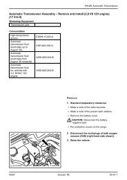
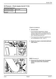
<strong>Engine</strong> <strong>electrical</strong> <strong>systems</strong> 5•5Never disconnect the battery terminals, oralternator multi-plug connector, when theengine is running.The battery leads and alternator multi-plugmust be disconnected before carrying out anyelectric welding on the car.Never use an ohmmeter of the typeincorporating a hand cranked generator forcircuit or continuity testing.Ignition and engine management<strong>systems</strong>Warning: The HT voltagegenerated by an electronicignition system is extremelyhigh, and in certaincircumstances could prove fatal. Take careto avoid receiving electric shocks from theHT side of the ignition system. Do nothandle HT leads, or touch the distributoror coil when the engine is running. Iftracing faults in the HT circuit, use wellinsulated tools to manipulate live leads.<strong>Engine</strong> management modules are verysensitive components, and certainprecautions must be taken to avoid damageto the module when working on a vehicleequipped with an engine management systemas follows.When carrying out welding operations onthe vehicle using electric welding equipment,the battery and alternator should bedisconnected.Although underbonnet-mounted modules(all except EEC IV) will tolerate normalunderbonnet conditions, they can beadversely affected by excess heat or moisture.If using welding equipment or pressurewashing equipment in the vicinity of themodule, take care not to direct heat, or jets ofwater or steam at the module. If this cannot beavoided, remove the module from the vehicle,and protect its wiring plug with a plastic bag.Before disconnecting any wiring, orremoving components, always ensure that theignition is switched off.On models with underbonnet-mountedmodules, do not run the engine with the moduledetached from the body panel, as the body actsas an effective heat sink, and the module maybe damaged due to internal overheating.Do not attempt to improvise fault diagnosisprocedures using a test lamp or multimeter,as irreparable damage could be caused to themodule.After working on ignition/enginemanagement system components, ensurethat all wiring is correctly reconnected beforereconnecting the battery or switching on theignition.On some early Bosch distributors it ispossible that with the distributor cap removed,if the engine is cranked, the cap securing clipsmay fall inward and jam the triggerwheel/vane, knocking it out of alignment. If thishappens, the distributor will have to berenewed as the trigger wheel/vane cannot berepositioned. Care should therefore be takennot to crank the engine with the distributor capremoved. Later distributors have redesignedclips which eliminate the problem.2 Battery - removal and refittingRemoval1 The battery is located in the enginecompartment on the left-hand side of thebulkhead.2 Disconnect the leads at the negative (earth)terminal by unscrewing the retaining nut andremoving the bulb. Pull off the plastic cover,and disconnect the positive terminal leads inthe same way.3 Unscrew the clamp bolt sufficiently toenable the battery to be lifted from its location(see illustration). Keep the battery in anupright position to avoid spilling electrolyte onthe bodywork.Refitting4 Refitting is a reversal of removal, but smearpetroleum jelly on the terminals whenreconnecting the leads, and always connectthe positive lead first and the negative lead last.3 Battery - testing and chargingTestingStandard and low maintenance battery1 If the vehicle covers a small annual mileageit is worthwhile checking the specific gravityof the electrolyte every three months todetermine the state of charge of the battery.Use a hydrometer to make the check andcompare the results with the following table.Ambient temperature:above 25ºC below 25ºCFully charged 1.21 to 1.23 1.27 to 1.2970% charged 1.17 to 1.19 1.23 to 1.25Fully discharged 1.05 to 1.07 1.11 to 1.13Note that the specific gravity readings assumean electrolyte temperature of 15ºC (60ºF); forevery 10ºC (50ºF) below 15ºC (60ºF) subtract0.007. For every 10ºC(50ºF) above 15ºC(60ºF)add 0.007.2 If the battery condition is suspect firstcheck the specific gravity of electrolyte ineach cell. A variation of 0.040 or morebetween any cells indicates loss of electrolyteor deterioration of the internal plates.3 If the specific gravity variation is 0.040 ormore, the battery should be renewed. If thecell variation is satisfactory but the battery isdischarged, it should be charged asdescribed later in this Section.Maintenance-free battery4 In cases where a “sealed-for-life”maintenance-free battery is fitted, topping-upand testing of the electrolyte in each cell is notpossible. The condition of the battery cantherefore only be tested using a batterycondition indicator or a voltmeter.5 If testing the battery using a voltmeter,connect the voltmeter across the battery andcompare the result with those given in theSpecifications under “charge condition”. Thetest is only accurate if the battery has notbeen subject to any kind of charge for theprevious six hours. If this is not the case,switch on the headlights for 30 seconds, thenwait four to five minutes before testing thebattery after switching off the headlights. Allother <strong>electrical</strong> components must be switchedoff, so check that the doors and tailgate arefully shut when making the test.6 If the voltage reading is less than 12.2 volts,then the battery is discharged, whilst areading of 12.2 to 12.4 volts indicates apartially discharged condition.7 If the battery is to be charged, first removeit from the vehicle.ChargingStandard and low maintenance battery8 Charge the battery at a rate of 3.5 to 4amps and continue to charge the battery atthis rate until no further rise in specific gravityis noted over a four hour period.9 Alternatively, a trickle charger charging at therate of 1.5 amps can be safely used overnight.10 Specially rapid “boost” charges which areclaimed to restore the power of the battery in1 to 2 hours are not recommended as theycan cause serious damage to the batteryplates through overheating.11 While charging the battery, note that thetemperature of the electrolyte should neverexceed 37.8ºC (100ºF).Maintenance-free battery12 This battery type takes considerablylonger to fully recharge than the standardtype, the time taken being dependent on theextent of discharge, but it can take anythingup to three days.13 A constant voltage type charger isrequired, to be set, when connected, to 13.9to 14.9 volts with a charger current below 25amps. Using this method the battery shouldbe useable within three hours, giving a voltagereading of 12.5 volts, but this is for a partiallydischarged battery and, as mentioned, fullcharging can take considerably longer.14 If the battery is to be charged from a fullydischarged state (condition reading less than12.2 volts) have it recharged by your <strong>Ford</strong>dealer or local automotive electrician as thecharge rate is higher and constant supervisionduring charging is necessary.2.3 Battery securing clamp and bolt5
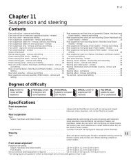
5•6 <strong>Engine</strong> <strong>electrical</strong> <strong>systems</strong>4.2a Disconnecting the multi-plug from aBosch alternator4 Alternator - removal andrefittingRemoval1 Disconnect the battery leads.2 Disconnect the multi-plug, or disconnectthe wires from their terminals on the rear ofthe alternator, noting their locations (asapplicable), then slacken the mounting andadjustment bolts and tilt the alternatortowards the engine (see illustrations).3 Remove the drivebelt(s) from the alternatorpulley(s).4 Remove the mounting and adjustment nutsand bolts, and withdraw the alternator fromthe engine.Refitting5 Refitting is a reversal of removal, noting thefollowing points.6 To avoid breakage of the alternatormounting bracket lugs, it is important that thefollowing procedure is adhered to whenrefitting the mounting bolts.7 Always refit the large flat washer (A) (seeillustration).8 Earlier models (before 1985) also have asmall washer (B) which must be fitted betweenthe sliding bush and the mounting bracket.9 Ensure that the bushes and bolts areassembled as shown - except on 2.0 litreDOHC models where a through-bolt is used,then tension the drivebelt(s) and tighten themounting and adjustment bolts as shown inthe relevant illustration in <strong>Chapter</strong> 3.4.2b Removing the insulating cap from themain wiring terminal on a Lucas A127alternator (CVH model)5 Alternator drivebelt(s) - checking,renewal and tensioningRefer to <strong>Chapter</strong> 1, Section 21.6 Alternator - testingNote: To carry out the complete test procedureuse only the following test equipment - a 0 to20 volt moving coil voltmeter, a 0 to 100 ampmoving coil ammeter, and a rheostat rated at30 amps.1 Check that the battery is at least 70%charged by using a hydrometer.2 Check the drivebelt tension.3 Check the security of the battery leads,alternator multi-plug, and interconnecting wire.Cable continuity check4 Pull the multi-plug from the alternator andswitch on the ignition, being careful not to crankthe engine. Connect the voltmeter between agood earth and each of the terminals in themulti-plug in turn. If battery voltage is notindicated, there is an open circuit in the wiringwhich may be due to a blown ignition warninglight bulb if on the small terminal.Alternator output check5 Connect the voltmeter, ammeter andrheostat as shown (see illustration). Run theengine at 3000 rpm and switch on theheadlamps, heater blower and, where fitted,the heated rear window. Vary the resistance4.7 Alternator mounting bracketarrangementA Large flat washerB Small flat washer (models up to 1985 only)C Mounting bracket (engine)D Mounting lugs (alternator)to increase the current and check that thealternator rated output is reached without thevoltage dropping below 13 volts.Charging circuit positive sidecheck6 Connect the voltmeter as shown (seeillustration). Start the engine and switch onthe headlamps. Run the engine at 3000 rpmand check that the indicated voltage dropdoes not exceed 0.5 volt. A higher readingindicates a high resistance such as a dirtyconnection on the positive side of thecharging circuit.Charging circuit negative sidecheck7 Connect the voltmeter as shown (seeillustration). Start the engine and switch onthe headlamps. Run the engine at 3000 rpmand check that the indicated voltage dropdoes not exceed 0.25 volt. A higher readingindicates a high resistance such as a dirtyconnection on the negative side of thecharging circuit.Voltage regulator check8 Connect the voltmeter and ammeter asshown (see illustration). Run the engine at3000 rpm and when the ammeter records acurrent of 3 to 5 amps check that the voltmeterrecords 13.7 to 14.15 volts. If the result isoutside the limits the regulator is faulty.6.5 Alternator output test circuit6.6 Alternator positive check circuit6.7 Alternator negative check circuit
<strong>Engine</strong> <strong>electrical</strong> <strong>systems</strong> 5•76.8 Alternator voltage regulator test circuit7.2 Withdrawing the regulator/brush boxfrom a Bosch alternator7.3 Compare the brush length with the figurein the Specifications - Bosch alternator7 Alternator brushes - removal,inspection and refitting1 Remove the alternator.Bosch type2 Remove the two securing screws andwithdraw the regulator/brush box assemblyfrom the rear of the alternator (seeillustration).3 If the length of either brush is less than theminimum given in the Specifications, unsolderthe wiring and remove the brushes and thesprings (see illustration).4 Wipe the slip rings clean with a fuelmoistenedcloth. If the rings are very dirty usefine glasspaper to clean them, then wipe withthe cloth (see illustration).5 Refitting is a reversal of removal, but makesure that the brushes move freely in theirholders.Lucas A 115 and A 133 type6 Disconnect the wiring plug, then removethe securing screw and withdraw theinterference suppression capacitor from therear cover.7 Extract the two securing screws andremove the alternator rear cover.8 Make a careful note of the fitted positions ofthe regulator wires, then disconnect the wiresfrom the diode pack and the brush box.9 Remove the regulator securing screws andwithdraw the regulator. Note that the regulatorsecuring screw also holds one of the brushmounting plates in position.10 Remove the two securing screws andwithdraw the brush box. Remove the securingscrews and lift the brushes from the brush box.11 If the length of either brush is less than theminimum given in the Specifications, renewboth brushes.12 Proceed as shown in paragraphs 4 and 5.Lucas A 127 type13 Where applicable, for improved accessremove the terminal cover from the rear of thealternator, then remove the three screwssecuring the regulator/brush box assembly tothe rear of the alternator (see illustration).14 Tip the outside edge of the assemblyupwards, and withdraw it from its location.Disconnect the wiring plug and withdraw theassembly from the alternator (seeillustration).15 If the length of either brush is less than theminimum given in the Specifications, thecomplete regulator/brush box assembly mustbe renewed (see illustration).16 Proceed as described in paragraphs 4and 5 (see illustration).7.4 Inspect the condition of the slip rings(arrowed) - Bosch alternator7.13 Removing the terminal cover from aLucas A127 alternator.Motorola type17 Remove the two securing screws andwithdraw the regulator. Disconnect theregulator wires after noting their locations.18 Remove the single securing screw (35 and45 amp types) or two securing screws (55 and70 amp types) and carefully withdraw thebrush box.19 If the length of either brush is less than theminimum given in the Specifications, thebrush box must be renewed.20 Proceed as shown in paragraphs 4 and 5.57.14 Disconnect the wiring plug andwithdraw the regulator/brushbox - LucasA127 alternator7.15 Compare the brush length with thefigure given in the Specifications - LucasA127 alternator7.16 Inspect the condition of the slip rings(arrowed) - Lucas A127 alternator
5•8 <strong>Engine</strong> <strong>electrical</strong> <strong>systems</strong>7.28 Stator-to-diode pack connections (A)and brushbox-to-diode pack terminal (B) -Mitsubishi alternatorMitsubishi type21 Unscrew the pulley nut. To prevent theshaft rotating, insert an Allen key in the end ofthe shaft.22 Remove the spring washer, pulley, fan,spacer and dust shield.23 Scribe an alignment mark along the lengthof the alternator to facilitate reassembly of thedrive end housing, stator and rear housing.24 Unscrew the through-bolts and withdrawthe drive end housing from the rotor shaft.25 Remove the seal and spacer from therotor shaft.26 Remove the rotor from the rear housingand the stator. This may require theapplication of local heat to the rear housingusing a large soldering iron. Do not use a heatgun, as this may result in damage to thediodes.27 Unscrew the four securing bolts andwithdraw the diode pack stator assemblyfrom the rear housing.28 Unsolder the stator leads from the diodepack terminals. Use a pair of pliers whenunsoldering to act as a heat sink, otherwisedamage to the diodes may occur (seeillustration).29 If the length of either brush is less than theminimum given in the Specifications, thebrush box must be renewed.30 To renew the brush box, unsolder theconnection to the diode pack, and solder the9.4 Starter motor solenoid winding testcircuitA Battery terminalB Motor terminalC Spade terminal8.3 Solenoid wiring connections on LucasM79 starter motor- CVH engineconnection to the new brush box. Use a pairof pliers as a heat sink to avoid damage to thediodes.31 Examine the surfaces of the slip rings.Clean them with a fuel moistened cloth, or ifnecessary fine glasspaper and then the cloth.32 Solder the stator leads to the diode packterminals, again using a pair of pliers as a heatsink.33 Refit the diode pack/stator assembly tothe rear housing and tighten the securingbolts.34 Insert a thin rod (an Allen key is ideal)through the hole in the rear housing to holdthe brushes in the retracted position.35 Fit the rotor to the rear housing and thenremove the temporary rod to release thebrushes.36 Reassemble the remaining componentsby reversing the dismantling operations. Makesure that the scribed marks are in alignment.8 Starter motor - removal andrefittingRemoval1 Apply the handbrake, jack up the front ofthe vehicle and support on axle stands (see“Jacking and Vehicle Support”).2 Disconnect the battery negative lead.3 Working underneath the vehicle, unscrew9.5 Starter motor solenoid continuity testcircuitA Battery terminalB Motor terminalC Spade terminal8.5 Unscrew the starter motor mountingboltsthe nut and disconnect the main cable fromthe starter solenoid (see illustration).4 Disconnect the ignition switch wire from thesolenoid.5 Unscrew the three mounting bolts andwithdraw the starter motor from the gearboxbellhousing (see illustration).Refitting6 Refitting is a reversal of removal.9 Starter motor - testing in thevehicle1 If the starter motor fails to operate firstcheck the condition of the battery.2 Check the security and condition of allrelevant wiring.Solenoid check3 Disconnect the battery negative lead and allleads from the solenoid.4 Connect a 3 watt test lamp and a 12 voltbattery between the starter terminal on thesolenoid and the solenoid body as shown(see illustration). The testlamp should light. Ifnot, there is an open circuit in the solenoidwindings.5 Now connect an 18 watt testlamp betweenboth solenoid terminals (see illustration),then energise the solenoid with a further leadto the spade terminal. The solenoid should beheard to operate and the testlamp shouldlight. Reconnect the solenoid wires.On load voltage check6 Connect a voltmeter across the batteryterminals, then disconnect the low tensionlead from the coil positive terminal andoperate the starter by turning the ignitionswitch. Note the reading on the voltmeterwhich should not be less than 10.5 volts.7 Now connect the voltmeter between thestarter motor terminal on the solenoid and thestarter motor body. With the coil low tensionlead still disconnected operate the starterand check that the recorded voltage is notmore than 1 volt lower than that noted inparagraph 6. If the voltage drop is more than1 volt a fault exists in the wiring from thebattery to the starter.
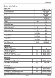
5•10 <strong>Engine</strong> <strong>electrical</strong> <strong>systems</strong>10.14 Bosch EV starter motor brush assembly1 Commutator end housing cap2 C-clip3 Shims4 Commutator end housingpositively located when the commutator endhousing screws are fitted.Bosch DM and DW types18 The procedure is basically as describedpreviously for the Bosch short frame and EFtype starter motors, except that a commutatorend plate is fitted in place of the end housing(see illustrations).Lucas 5M90 typeNote: New star clips must be obtained for thearmature shaft on reassembly19 With the starter motor removed from thevehicle and cleaned, grip the unit in a vicefitted with soft jaw protectors.20 Remove the plastic cap from the end ofthe armature shaft, then remove the star clipfrom the end of the shaft, using a chisel at anangle of 45º to the shaft to distort the prongs5 Brushes6 Brush plate7 Yoke8 Commutator end housing screwof the clip until it can be removed (seeillustrations).21 Unscrew the two securing nuts andremove the connector cable from the mainfeed terminal (see illustration).22 Extract the two commutator end platesecuring screws, and carefully tap the endplate to free it. Lift the end plate clear to allowaccess to the two field brushes. Disconnectthe two field brushes from the brush box toallow complete removal of the commutatorend plate. Take care not to damage thegasket as the end plate is removed.23 Remove the nut, washer and insulatorfrom the main terminal stud on thecommutator end plate, then push the studand the second insulator through the endplate and unhook the brushes.24 To remove the brush box, drill out therivets securing the brush box to the end plate,then remove the brush box and gasket.10.18a Bosch DM starter motor brush assembly1 Yoke2 Brush plate3 Commutator end housing4 Seal5 Shim6 C-clip7 Commutator end housing cap8 Securing screw9 Commutator end housingsecuring screw25 If the brushes have worn to less than thespecified minimum, renew them as a set. Torenew the brushes, cut the leads at theirmidpoint and make a good soldered jointwhen connecting the new brushes.26 The commutator face should be clean andfree from burnt spots. Where necessaryburnish with fine glass paper (not emery) andwipe with a fuel-moistened cloth.27 Commence reassembly by positioning thebrush box gasket on the commutator endplate, then position the brush box on thegasket and rivet the brush box to the endplate. Use a new gasket if necessary.28 Fit the main terminal stud and insulator tothe commutator end plate, then secure thestud with the remaining insulator, washer andnut. Fit the two brushes which are attached tothe terminal stud into their respectivelocations in the brush box.10.18b Bosch DW starter motor brush assembly1 Commutator end plate securingscrew2 Commutator end plate cap3 C-clip4 Shim5 Commutator end plate6 Brush plate7 Yoke10.20a Remove the plastic cap from the end of the armatureshaft . . .
<strong>Engine</strong> <strong>electrical</strong> <strong>systems</strong> 5•1110.21 Lucas 5M90 startermotor brush assembly1 Main terminal nuts andwashers2 Commutator end plate3 Brush box4 Brush spring5 Brushes6 Yoke7 Armature8 Thrustwasher9 Commutator end platesecuring screw10 Bush11 Thrustplate12 Star clip13 Plastic cap10.20b . . . followed by the star clip - Lucas 5M90 startermotor10.30 Use a soft faced hammer and socketto fit a new star clip to the end of thearmature shaft - Lucas 5M90 starter motor29 Fit the two field brushes into theirlocations in the brush box, then position thecommutator end plate on the yoke and fit thetwo securing screws.30 Fit a new star clip to the end of thearmature shaft, ensuring that the clip ispressed home firmly to eliminate any endfloatin the armature (see illustration). Fit theplastic cap over the end of the armature shaft.Lucas 8M90 type31 The procedure is basically as describedpreviously for the 5M90 type starter motorwith the following difference (see illustration):32 The commutator end plate is secured by twoscrews. The end plate and brush box are servicedas an assembly and should be renewed.Lucas M79 type33 With the starter motor removed from thevehicle and cleaned, grip the unit in a vicefitted with soft jaw protectors.34 Unscrew the securing nut and washer anddisconnect the wiring from the solenoid terminal.35 Remove the two screws securing thecommutator end housing cap. Remove the cap.36 Remove the C-clip and spacers from theend of the armature shaft.37 Remove the two commutator end housingsecuring screws and withdraw the endhousing.38 Separate the brush components (seeillustration).39 If the brushes have worn to less than thespecified minimum, renew them as a set. Torenew the brushes, cut the leads at theirmidpoint and make a good soldered jointwhen connecting the new brushes.40 The commutator face should be clean andfree from burnt spots. Where necessaryburnish with fine glass paper (not emery) andwipe with a fuel-moistened cloth.510.31 Lucas 8M90 starter motor brush assembly1 Plastic cap2 Star clip3 Commutator end plate screw4 Commutator end plate5 Brush box6 Yoke7 Pole securing screw8 Solenoid connector link9 Pole shoe10 Field coils10.38 Lucas M79 starter motor brush plate componentsA Brush plateB Brush plate insulatorC Brush holders and springsD BrushsE InsulatorsF Brush link
5•12 <strong>Engine</strong> <strong>electrical</strong> <strong>systems</strong>1 Yoke2 Solenoid connecting link3 Pole shoe4 Rubber grommet5 Brush6 Brush spring7 Brush plate10.47 Nippondenso starter motor brush assembly41 Locate the brush box over thecommutator, position the brushes, then fit thenylon cover over the brushes. Route the brushwiring into the locating channel, then securethe brushes in the channels with the lockingclips and springs.42 Refit the commutator end housing,locating the rubber block in the cut-out in thehousing, then secure with the two screws.43 Refit the spacers and C-clip to the end ofthe armature shaft, then fit the commutator endhousing cap and secure with the two screws.44 Reconnect the wiring to the solenoidterminal and fit the washer and securing nut.Nippondenso type45 With the starter motor removed from thevehicle and cleaned, grip the unit in a vicefitted with soft jaw protectors.46 Unscrew the retaining nut and washer anddisconnect the wiring from the terminal on thesolenoid.47 Remove the two screws securing thecommutator end housing cap and remove thecap (see illustration).48 Remove the C-clip from the groove in thearmature shaft, and remove the spring.49 Unscrew the two bolts and washers, andwithdraw the commutator end housing.50 Withdraw the two field brushes from thebrush plate, then remove the brush plate.51 If the brushes have worn to less than thespecified minimum, renew them as a set. Torenew the brushes, cut the leads at theirmidpoint and make a good soldered jointwhen connecting the new brushes.52 The commutator face should be clean andfree from burnt spots. Where necessaryburnish with fine glass paper (not emery) andwipe with a fuel-moistened cloth.8 Commutator end housing9 Bush10 Spring11 C-clip12 Commutator end housing cap13 Commutator end housing securingbolt53 Position the brush plate over the end ofthe armature, aligning the cut-outs in thebrush plate with the loops in the fieldwindings. The brush plate will be positivelylocated when the commutator end housingbolts are fitted.54 Fit the brushes to their locations in thebrush plate, and retain with the springs.55 Fit the commutator end housing andsecure with the two bolts and washers.56 Fit the spring and the C-clip to the end ofthe armature shaft, then smear the end of theshaft with a little lithium-based grease, andrefit the commutator end housing cap,securing with the two screws.57 Reconnect the wiring to the solenoidterminal and fit the washer and retaining nut.11 Spark plugs and HT leads -removal, inspection andrefittingNote: The correct functioning of the spark plugsis vital for the correct running and efficiency ofthe engine. It is essential that the plugs fitted areappropriate for the engine, and the suitable typeis specified at the beginning of this <strong>Chapter</strong>. Ifthis type is used and the engine is in goodcondition, the spark plugs should not needattention between scheduled replacementintervals. Spark plug cleaning is rarely necessaryand should not be attempted unless specialisedequipment is available as damage can easily becaused to the firing ends.Removal1 Where necessary, for improved accessremove the air cleaner and/or the inlet hose.2 If necessary, identify each HT lead forposition, so that the leads can be refitted to theircorrect cylinders, then disconnect the leadsfrom the plugs by pulling on the connectors, notthe leads. Note that the position of No 1 cylinderHT lead in the distributor cap is marked witheither a pip, or a number “1 “.3 On 2.0 litre DOHC carburettor models, thelocation of the spark plugs and the closeproximity of the carburettor makes spark plugaccess difficult, particularly when removingthe plugs from cylinders 2 and 3. It issuggested that a 3/8 inch ratchet drive sparkplug socket with rubber insert and longextension bar is used, possibly in conjunctionwith a universal joint adapter. It is alsoadvisable to disconnect No 3 cylinder HT leadfrom the distributor first, to allow some slackfor disconnection at the spark plug.4 Clean the area around each spark plugusing a small brush, then using a plugspanner (preferably with a rubber insert),unscrew and remove the plugs. Cover thespark plug holes with a clean rag to preventthe ingress of any foreign matter.Inspection5 The condition of the spark plugs will tellmuch about the overall condition of the engine.6 If the insulator nose of the spark plug is cleanand white, with no deposits, this is indicative ofa weak air/fuel mixture, or too hot a plug. (A hotplug transfers heat away from the electrodeslowly - a cold plug transfers it away quickly).7 If the tip and insulator nose is covered withhard black-looking deposits, then this isindicative that the mixture is too rich. Shouldthe plug be black and oily, then it is likely thatthe engine is fairly worn, as well as the mixturebeing too rich.8 If the insulator nose is covered with light tanto greyish brown deposits, then the mixture iscorrect and it is likely that the engine is ingood condition.9 The spark plug gap is of considerableimportance, as, if it is too large or too small,the size of the spark and its efficiency will beseriously impaired. The spark plug gap shouldbe set to the figure given in the Specificationsat the beginning of this <strong>Chapter</strong>. To set it,measure the gap with a feeler blade, and thenbend open, or close the outer plug electrodeuntil the correct gap is achieved (seeillustrations). The centre electrode shouldnever be bent as this may crack the insulationand cause plug failure, if nothing worse.11.9a Measuring a spark plug gap using afeeler blade
<strong>Engine</strong> <strong>electrical</strong> <strong>systems</strong> 5•1311.9b Measuring a spark plug gap using awire gauge11.9c Adjusting a spark plug gap using aspecial tool10 The distributor cap (except on 1.6 and 1.8litre CVH (R6A type) engines) and the HTleads should be cleaned and checked at thespecified intervals. To test the HT leads,remove them together with the distributorcap, then connect an ohmmeter to the end ofeach lead and its appropriate terminal withinthe cap in turn (see illustration). If theresistance of any lead is greater than themaximum given in the Specifications, checkthat the lead connection in the cap is goodbefore renewing the lead.Refitting11 Before fitting the spark plugs, check thatthe threaded connector sleeves are tight andthat the plug exterior surfaces are clean. Asthe plugs incorporate taper seats also makesure that the threads and seats are clean.12 On DOHC models before refitting the12.1 Ignition coil - CVH model. Plasticcover arrowed12.4 Ignition coil (A) and suppressor (B)viewed from under vehicle (shroud removed)spark plugs, coat their threads with suitableantiseize compound, taking care not tocontaminate the electrodes.13 Screw in the spark plugs by hand, thentighten them to the specified torque. Do notexceed the torque figure.14 Push the HT leads firmly onto the sparkplugs, and where applicable refit the aircleaner and/or inlet hose.12 Coil - testing, removal andrefittingTestingAll models except 1.6 and 1.8 litreCVH (R6A type)1 The coil is located on the left-hand side ofthe engine compartment and is retained by ametal strap (see illustration). It is of highoutput type and the HT tower should be keptclean at all times to prevent possible arcing.Bosch and Femsa coils are fitted withprotective plastic covers and Polmot coils arefitted with an internal fusible link.2 To ensure that the correct HT polarity at thespark plugs, the LT coil leads must always beconnected correctly. The black lead mustalways be connected to the terminal marked +115, and the green lead to the terminalmarked /1. Incorrect connections can causepoor starting, misfiring, and short spark pluglife.3 To test the coil first disconnect the LT andHT leads. Connect an ohmmeter between12.7 Disconnecting the HT lead from thecoil11.10 Method of testing an HT lead with anohmmeterboth LT terminals and check that the primarywinding resistance is as given in theSpecifications. Connect the ohmmeterbetween the HT terminal and either LTterminal and check that the secondarywinding resistance is as given in theSpecifications. If either winding resistance isnot as specified, the coil should be renewed.Reconnect the LT and HT leads oncompletion.1.6 and 1.8 litre (R6A type) CVHmodels4 The coil fitted to these models is locatedtowards the front right-hand side of thecylinder block (see illustration).5 Testing of the coil should be entrusted to a<strong>Ford</strong> dealer or a suitable specialist.RemovalAll models except 1.6 and 1.8 litreCVH (R6A type)6 Disconnect the battery negative lead,7 Disconnect the LT and HT leads from thecoil (see illustration).8 Remove the securing screw(s) and detachthe coil and strap assembly from the bodypanel. Note that on models with the ESCsystem, the coil strap is secured by the topESC module securing screw. On certainmodels with the ESC II or EEC IV <strong>systems</strong>, an“octane adjustment” service lead may beconnected to one of the coil securing screws.On 2.0 litre DOHC fuel-injected models, thecoil/ignition module heat shield must beremoved for access to the coil securing bolts.The heat shield is secured by two screws.Note that on certain models, an earthing lead5
5•14 <strong>Engine</strong> <strong>electrical</strong> <strong>systems</strong>12.8a Ignition coil viewed with heat shieldremovedand/or a suppressor may be secured by oneof the coil securing bolts (see illustrations).1.6 and 1.8 litre (R6A type) CVHmodels9 Disconnect the battery negative lead.10 Remove the two securing screws, andwithdraw the plastic ignition module shroud.11 Disconnect the ignition coil wiring plugand, where fitted, the suppressor wiring plug,pulling on the plugs, not on the wiring (seeillustrations).12 Release the securing lugs, and disconnectthe HT leads from the coil, noting theirlocations to aid refitting.13 Remove the four Torx screws, andwithdraw the coil from the cylinder block.Refitting14 Refitting is a reversal of removal, butensure that all leads are securely connected.13.2 Unclipping the distributor screeningcan - Motorcraft distributor12.8b Suppressor secured by one of thecoil securing bolts13 Distributor cap and rotor arm(OHC models) - removal andrefittingSOHC models1 Disconnect the battery negative lead.2 Where applicable, unclip the screening canfrom the top of the distributor and disconnectthe earth strap (see illustration).3 If necessary, identify each HT lead forposition, so that the leads can be refitted totheir correct cylinders, then disconnect theleads from the spark plugs by pulling on theconnectors, not the leads. Similarly,disconnect the HT lead from the coil. Whereapplicable, slide the HT lead holder from theclip on the camshaft cover (see illustration).Lucas distributors4 Remove the two securing screws and lift offthe distributor cap.5 The rotor arm is a push-fit on the end of thedistributor shaft.6 Refitting is a reversal of removal, noting thatthe rotor arm can only be fitted in oneposition. Ensure that the HT leads arecorrectly connected.Bosch distributors7 Prise away the spring clips with ascrewdriver and lift off the distributor cap (seeillustration). On fuel injection models,disconnect the crankcase ventilation hosefrom the air inlet hose, then disconnect the airinlet hose from the inlet manifold and theairflow meter for improved access.12.11a Disconnecting the coil wiring plug . . .12.11b . . . and the suppressor wiring plug8 Refitting is a reversal of removal, noting thatthe rotor arm can only be fitted in one position.Ensure that the HT leads are correctlyconnected, and on fuel injection modelsensure that the air inlet hose clips are correctlyaligned (refer to illustration, Section 15,<strong>Chapter</strong> 4, Part B).Motorcraft distributors9 For improved access, disconnect thecrankcase ventilation hose from the air inlethose, then disconnect the air inlet hose fromthe inlet manifold and the airflow meter forimproved access.10 Remove the two securing screws and liftoff the distributor cap (see illustration).11 Remove the two securing screws andwithdraw the rotor arm (disc) (seeillustration). Note that on some vehicles, therotor arm tip may be coated with siliconegrease to assist radio interferencesuppression. Do not attempt to clean thegrease off if it is present. If radio interference13.3 HT lead holder on camshaft cover13.7 Securing distributor cap with springclip - Bosch distributor13.10 Removing a distributor cap securingscrew - Motorcraft distributor
<strong>Engine</strong> <strong>electrical</strong> <strong>systems</strong> 5•1513.11 Removing a rotor arm (disc) securingscrew - Motorcraft distributor13.14a Unclipping the lower section . . .13.14b . . . and the upper section of thedistributor shieldproblems are experienced, consult a <strong>Ford</strong>dealer or an in-car entertainment specialist.12 Proceed as described in paragraph 6, butadditionally ensure that the air inlet hose clipsare correctly aligned (refer to illustration,Section 15, <strong>Chapter</strong> 4, Part B).DOHC models13 Disconnect the battery negative lead.14 Unclip the lower section of the distributorshield from the upper section, then unscrewthe two securing nuts, and withdraw theupper section of the shield from the studs onthe upper timing chain cover (seeillustrations).15 If necessary, identify each HT lead forposition, so that the leads can be refitted totheir correct cylinders, then disconnect theleads from the spark plugs by pulling on the13.17 Removing the distributor cap androtor armconnectors, not the leads. Similarly,disconnect the HT lead from the coil, andrelease it from the clip on the timing chaincover.16 Using a suitable Torx key or socket,unscrew the two distributor cap securingscrews, then lift off the cap.17 The rotor arm is a push-fit on the end ofthe rotor shaft (see illustration).18 If desired, the rotor housing can be pulledfrom the timing chain cover.19 Refitting is a reversal of removal, ensuringthat the rotor arm is pushed fully home on therotor shaft. Make sure that the HT leads arefitted to their correct cylinders. Note that therotor arm will only fit in one position.14 Distributor components (CVHmodels) - removal and refitting1 The distributor fitted to the CVH engine isunlike any conventional distributor, in that ithas no main body and no adjustments arepossible. The distributor is used purely todistribute HT voltage to the spark plugs. Toremove the distributor components, proceedas follows.2 Disconnect the battery negative lead.Distributor cap3 Pull the two halves of the distributor capshroud apart and remove the shroud.Disconnect the earth strap from the tag on thetiming cover (see illustration).4 If necessary, identify each HT lead forposition, so that the leads can be refitted totheir correct cylinders, then disconnect theleads from the spark plugs by pulling on theconnectors, not the leads. Unclip the HT leadholders from their studs on the camshaftcover (see illustration).5 Depress the two securing screws and turnthem anti-clockwise through 90º, then lift offthe distributor cap.6 Disconnect the HT lead from the coil bypulling on the connector not the lead, andremove the distributor cap.7 Refitting is a reversal of removal, but ensurethat the HT leads are fitted to their correctcylinders.Rotor arm and housing8 With the distributor cap removed asdescribed previously, compress the two lugson the rotor shaft and withdraw the rotor arm(see illustration).9 The rotor housing can now be removed bypulling it from the timing cover (seeillustration).10 Refitting is a reversal of removal, but notethat the rotor arm can only be fitted in oneposition.Rotor shaft11 The rotor shaft is retained by the camshaftsprocket bolt.12 To remove and refit the rotor shaft, firstremove the timing cover and the camshaft514.3 Distributor cap shroud earth strapconnection14.4 HT lead holders (arrowed) oncamshaft cover14.8 Removing the rotor arm
5•16 <strong>Engine</strong> <strong>electrical</strong> <strong>systems</strong>sprocket bolt. Note that there is no need toremove the timing belt or the sprockets.15 Distributor (OHC models) -removal and refittingNote: During production the engine ignitiontiming is accurately set using a microwaveprocess, and sealant is applied to thedistributor clamp bolt. Removal of thedistributor should be avoided except whereexcessive bearing wear has occurred due tohigh mileage or during major engine overhaul.A timing light will be required to check theignition timing after refitting the distributor.All models except early“Economy”Removal1 Disconnect the battery negative lead.2 If necessary, identify each HT lead forposition, so that the leads can be refitted totheir correct cylinders, then disconnect theleads from the spark plugs by pulling on theconnectors, not the leads.3 Where applicable, unclip the screening canfrom the top of the distributor and disconnectthe earth strap. On fuel injection models,disconnect the crankcase ventilation hosefrom the air inlet hose, then disconnect the airinlet hose from the inlet manifold and theairflow meter for improved access.15.6 Disconnecting vacuum pipe fromvacuum advance unit - Bosch distributor14.9 Removing the rotor housing4 Prise away the spring clips with ascrewdriver, or remove the two securingscrews, as applicable, and lift off thedistributor cap.5 Disconnect the HT lead from the coil bypulling on the connector, not the lead, thenslide the HT lead holder from the clip on thecamshaft cover, and withdraw the distributorcap.6 Where applicable, disconnect the vacuumpipe from the vacuum advance unit on theside of the distributor (see illustration).7 Using a suitable socket or spanner on thecrankshaft pulley bolt, turn the crankshaft tobring No 1 cylinder to the firing point. If thedistributor cap is secured by clips, make surethat the clips stay clear of the distributor15.7a Lucas distributor showing triggervane position No 1 cylinder at firing pointA Trigger vane cut B Sensor-outmoving parts. No 1 cylinder is at the firingpoint when:a) The relevant timing marks are inalignment.b) The tip of the rotor arm is pointing to theposition occupied by the No 1 cylinder HTlead terminal in the distributor cap. Notethat the position of No 1 HT lead terminalis identified by a pip or a number “1”c) On Lucas distributors, the cut-out in thetrigger vane is aligned with the sensor(see illustration)d) On Bosch distributors, the tip of the rotorarm is aligned with the scribed line on thedistributor body (where applicable,remove rotor arm and dust cover, thenrefit rotor arm to check alignment withscribed line) (see illustration)e) On Motorcraft distributors, the tip of therotor arm is aligned with a notch in thedistributor body. Mark the relevant notch(there may be several) for reference whenrefitting. Also, the leading edge of one ofthe trigger vane segments is aligned withthe rib on the sensor (remove the twosecuring screws and lift off the rotor armto view the trigger vane and sensor) (seeillustration).8 Disconnect the distributor wiring plug,where applicable depressing the lockingtab(s). Pull on the plug, not the wiring (seeillustration).9 Make alignment marks between thedistributor body and the cylinder block.10 Scrape the sealant from the distributorclamp bolt, then unscrew and remove the boltand clamp (see illustration).11 Withdraw the distributor from the cylinderblock. As the distributor is removed, the rotorarm will turn clockwise due to the skew geardrive. Note the new position of the rotor armrelative to the distributor body, if necessarymaking an alignment mark (some distributorsalready have an alignment mark).12 Check the distributor spindle forexcessive side-to-side movement. If evident,the distributor must be renewed, as the onlyspares available are the cap, rotor arm,module (where applicable), and driveshaftO-ring (see illustration).15.7b Rotor arm tip aligned with scribedline on distributor body - Bosch distributor15.7c Trigger vane segment leading edgealigned with sensor rib - Motorcraftdistributor15.8 Disconnecting distributor wiring plug- Bosch distributor
<strong>Engine</strong> <strong>electrical</strong> <strong>systems</strong> 5•1731 Connect the adapter loom to thedistributor.32 Start the engine, and adjust the ignitiontiming to the value given in the Specificationsat the beginning of this <strong>Chapter</strong>. Work asdescribed above whilst noting that thevacuum pipe must be left connected.16 Ignition timing (OHC models)- adjustment15.10 Unscrewing distributor clamp bolt -Bosch distributorRefitting13 Commence refitting by checking that No 1cylinder is still at the firing point. The relevanttiming marks should be aligned. If the enginehas been turned whilst the distributor hasbeen removed, check that No 1 cylinder is onits firing stroke by removing the No 1 cylinderspark plug and placing a finger over the plughole. Turn the crankshaft until compressioncan be felt, which indicates that No 1 piston isrising on its firing stroke. Continue turning thecrankshaft until the relevant timing marks arein alignment.14 Turn the rotor arm to the position noted inparagraph 11. If a new distributor is beingfitted, and no alignment marks are present,transfer the marks from the old distributor tothe new distributor.15 Hold the distributor directly over theaperture in the cylinder block with thepreviously made marks on the distributorbody and cylinder block aligned, then lowerthe distributor into position. Again, if a newdistributor is being fitted, transfer thealignment mark from the old distributor bodyto the new distributor body. As the skew geardrive meshes, the rotor arm will turnanti-clockwise.16 With the distributor fitted and the markson the distributor body and cylinder blockaligned, check that the rotor arm is positionedas described in paragraph 7 - if not, withdrawthe distributor, re-position the driveshaft andtry again.17 Refit the clamp, then insert and tightenthe bolt. Do not fully tighten the bolt at thisstage.18 Refit the distributor wiring plug, andwhere applicable reconnect the vacuum pipe,and refit the dust cover and/or rotor arm.19 Refit the distributor cap, and reconnectthe HT leads to the spark plugs and coil.Ensure that the leads are refitted to theircorrect cylinders.20 Where applicable, refit the screening canto the top of the distributor and reconnect theearth strap. On fuel injection models,reconnect the air inlet hose, ensuring that theclips are correctly aligned (refer to illustration,Section 15, <strong>Chapter</strong> 4, Part B).15.12 Removing distributor driveshaft O-ring - Motorcraft distributor21 Reconnect the battery negative lead.22 Check and if necessary adjust the ignitiontiming.Early “Economy” modelsRemoval23 Removal of the distributor fitted to thesemodels is a similar process to that describedabove.Refitting24 Turn the crankshaft to bring No 1 cylinderto the firing point, with the 16º BTDC mark onthe crankshaft pulley aligned with the pointeron the crankshaft front oil seal housing, asdescribed above.25 Fit the new distributor to the engine asdescribed above, then proceed as follows.26 Cut the original distributor wiring plugfrom the wiring loom. Make the cut close tothe connector.27 Strip back 10 mm of insulation from eachof the wires on the wiring loom, and on theadapter loom supplied with the newdistributor.28 Solder the adapter loom wires to thecorresponding identically coloured wires inthe main loom.29 Carefully insulate each individual solderedjoint using insulating tape, then apply tape tocover the join between the looms.30 Fit a new distributor cap (and screeningcan, where applicable), and connect the HTleads.16.2a Highlighted timing marks - SOHCengine with cast crankshaft pulleyNote: During production the ignition timing isaccurately set using a microwave process,and sealant is applied to the distributor clampbolt. Because the electronic componentsrequire no maintenance, checking the ignitiontiming does not constitute part of the routinemaintenance schedule, and the procedure istherefore only necessary after removal andrefitting of the distributor. A timing light will berequired for this procedure. For details ofignition timing adjustment in order to operatevehicles on unleaded petrol refer to theappropriate Section of this <strong>Chapter</strong>.All models except 2.0 litre DOHC1 Before checking the ignition timing, thefollowing conditions must be met:a) The engine must be at normal operatingtemperatureb) Where applicable, the vacuum pipe to thedistributor vacuum unit or electronicmodule (as applicable) must bedisconnected from the vacuum unit orelectronic module and pluggedc) The idle speed must be below 900 rpm(isolate “idle speed adjustment” wire ifnecessary)d) Any earthed “octane adjustment” wiresmust be temporarily isolated2 Wipe clean the crankshaft pulley timingmarks and the pointer on the crankshaft frontoil seal housing. Note that two alternativetypes of pulley may be fitted (seeillustration). The desired timing values aregiven in the Specifications. If necessary, usewhite paint or chalk to highlight the relevanttiming mark(s) (see illustration).3 Connect a stroboscope timing light to theNo 1 cylinder HT lead, following themanufacturer’s instructions.4 With the engine idling at normal operatingtemperature, point the timing light at themarks on the crankshaft pulley, and checkthat the appropriate timing mark appearsstationary in line with the timing cover pointer.Take care not to get the timing light leads,clothing etc tangled in the cooling fan bladesor other moving parts of the engine.5 If adjustment is necessary, stop the engine,slacken the distributor clamp bolt, and turnthe distributor body slightly. Turn thedistributor body clockwise to retard theignition timing (move the timing closer to TDC)and anti-clockwise to advance the timing.5
5•18 <strong>Engine</strong> <strong>electrical</strong> <strong>systems</strong>16.2b Crankshaft pulley timing marks - SOHC engineA Cast pulleyNote that the required distributor bodymovement will be half of the requiredcrankshaft movement (ie an adjustment of 5ºin ignition timing will require the distributorbody to be turned 2º. Tighten the clamp boltand re-check the timing.6 On models with inductive discharge ignition<strong>systems</strong>, the mechanical and vacuumadvance mechanisms can be checked asfollows. On all other models, proceed toparagraph 10.7 With the engine idling, timing lightconnected, and vacuum pipe disconnected asdescribed in the preceding paragraphs,increase the engine speed to approximately2000 rpm (if desired, connect a tachometer tothe engine in accordance with themanufacturer”s instructions). Note theapproximate distance which the relevant pulleymark moves out of alignment with the pointer.8 Reconnect the vacuum pipe to thedistributor or electronic module, asapplicable, and repeat the procedure given inthe previous paragraph, when for the sameincrease in engine speed, the alignmentdifferential between the pulley mark andpointer should be greater than previouslyobserved.9 If the pulley mark does not appear to moveduring the first part of the check, a fault in thedistributor mechanical advance mechanism isindicated. No increased movement of themark during the second part of the checkindicates a punctured diaphragm in thedistributor vacuum unit, or a leak in thevacuum line.10 On completion of the adjustments andchecks, stop the engine and disconnect thetiming light. Where applicable, reconnect thevacuum pipe, if not already done, andreconnect any “octane adjustment” and “idlespeed adjustment” wires. Make a final checkto ensure that the distributor clamp bolt istight.11 Finally, the idle speed and mixture shouldbe checked and adjusted.B Pressed steel pulley2.0 litre DOHC carburettor model12 The ignition timing is controlled by theESC II module, and no adjustment is possible.2.0 litre DOHC fuel injectionmodel13 The ignition timing is controlled by theEEC IV module, and no adjustment ispossible.17 Ignition timing - adjustment foruse with unleaded petrolNote: Refer to the Specifications Section atthe beginning of this <strong>Chapter</strong> for ignitiontiming values for use with unleaded petrol.1 To run an engine on unleaded petrol,certain criteria must be met, and it may behelpful to first describe the various terms usedfor the different types of petrol:Normal leaded petrol (4-star, 97 RON):Petrol which has a low amount of lead addedduring manufacture (0.15 g/litre), in addition tothe natural lead found in crude oil.Unleaded petrol (Premium, 95 RON):Has no lead added during manufacture, butstill has the natural lead content of crude oil.Lead free petrol: Contains no lead. It hasno lead added during manufacture, and thenatural lead content is refined out. Thistype of petrol is not currently available forgeneral use in the UK and should not beconfused with unleaded petrol.2 To run an engine continuously on unleadedpetrol, suitable hardened valve seat insertsmust be fitted to the cylinder head.3 The OHC engines fitted to the <strong>Sierra</strong>/P100range which have suitable valve seat insertsfitted at manufacture can be identified byletters stamped on the cylinder head next toNo 4 spark plug as follows:1.6 litre engines M, MM, N, or NN1.6 litre engines S or SS2.0 litre engines L, P, PP, R, or RR4 All CVH engines have suitable valve seatinserts fitted.5 Vehicles which have no identification letterstamped on the cylinder head, and are notfitted with suitable valve seat inserts, may stillbe run on unleaded petrol (althoughcontinuous use is not recommended),provided that every fourth tank filling is ofnormal leaded petrol, ie: three tanks ofunleaded petrol followed by one tank ofnormal leaded petrol.6 When running an OHC engine on unleadedpetrol (Premium, 95 RON), the ignition timingmust be retarded as described in thefollowing sub-Sections. There is norequirement for ignition timing adjustmentwhen running CVH engines on unleadedpetrol.Inductive discharge ignitionsystem and ESC system7 On vehicles fitted with an inductivedischarge ignition system, or the ESC system,the ignition timing should be retarded asspecified.ESC II and EEC IV <strong>systems</strong>8 On vehicles fitted with the ESC II or EEC IV<strong>systems</strong>, there is a facility for retarding theignition timing without physically disturbingthe distributor.9 Adjustment is made by earthing one or twowires (“octane adjustment” wires) whichterminate in a wiring plug next to the ignitioncoil. Ideally a service adjustment lead,available from a <strong>Ford</strong> dealer should be used(see illustration). One end of the lead plugsinto the “octane adjustment” wiring plug, andthe other end should be earthed by fixing toone of the ignition coil securing screws.10 Cut and insulate the wires in the servicelead which are not to be earthed.17.9 Service adjustment lead and plug -ESC II and EEC IV <strong>systems</strong>A Red, blue and yellow wiresB PlugC Wire cutting point
<strong>Engine</strong> <strong>electrical</strong> <strong>systems</strong> 5•19SystemDegrees of retardationBlue wire Red wire Blue and redwires17.14 Lucar type “octaneadjustment” connectors -early models with ESC IIand EEC IV <strong>systems</strong>ESC II (except 1.8 litre)models from February1987 2 4 6ESC II (1.8 litre models fromFebruary 1987) 4 2 6EEC IV 4 2 6A Red, blue and yellow connectorsB Coil securing screw (earthing point)11 The amount of ignition retardationprovided by earthing the wire(s) is as shown inthe table above.12 Once the ignition timing has beenretarded, the vehicle can be operated oneither leaded or unleaded petrol.13 On 2.0 litre models, if the yellow wire (“idlespeed adjustment” wire) in the service lead isearthed, the idle speed will be raised by 75rpm. If the vehicle already has a single yellowfly lead connected prior to connecting theservice lead, ensure that the yellow wire in theservice lead is earthed.14 Note that some early models havecoloured “Lucar” connectors fitted in place ofthe “octane adjustment” wiring plug (seeillustration). The principle for ignition timingadjustment on these vehicles is as describedpreviously for vehicles with the “octaneadjustment” wiring plug.15 On completion of ignition timingadjustment, the idle speed and mixture shouldbe checked and adjusted as necessary.18 Electronic modules - removaland refittingNote: Refer to Section 1 for precautions to beobserved when working with electronicmodules.1 Disconnect the battery negative lead.All ESC modules except ESC(early “Economy” models)2 All modules except the ESC Hybrid moduleare mounted on the left-hand side of theengine compartment (see illustration). TheESC Hybrid module is mounted on theright-hand side of the engine compartment.3 Disconnect the module wiring plug bypulling on the plug, not the wiring. On ESC IImodules, except those fitted to 1.8 litremodels from February 1987, a locking tab atthe lower end of the wiring plug must bedepressed before unhooking the upper end ofthe plug from the module. On ESC II modulesfitted to 1.8 litre models from February 1987(see illustration) and ESC Hybrid modules,the wiring plug is secured by a screw which isintegral with the plug (see illustrations).4 Where applicable, disconnect the vacuumpipe from the module (see illustration).5 Remove the two or three securing screws,as applicable, and withdraw the module fromthe engine compartment. Note that the topsecuring screw of the ESC module alsosecures the ignition coil strap.6 Refitting is a reversal of removal, but ensurethat the underside of the module and thecorresponding area of the body panel are clean.ESC module (early “Economy”models)18.2 ESC module securing screws (arrowed)A Wiring plug B Vacuum pipe18.3a ESC II module - 1.8 litre models fromFebruary 19877 Remove the module complete with itssecuring bracket, as described above.8 Fit the new module, slightly behind the oldmodule position, on the flat vertical surface ofthe body panel, and secure with the twoscrews supplied. Note that the module mustbe mounted against the flat area of the bodypanel to prevent distortion of the module, andto ensure good heat transfer from the moduleto the body.9 Reconnect the module vacuum pipe.10 Connect the adapter loom supplied withthe new module between the module and theold module’s wiring plug.11 Where applicable, refit the coil to itsoriginal location.518.3b Disconnecting ESC II module wiringplug18.3c Disconnecting ESC Hybrid modulewiring plug18.4 Disconnecting ESC II module vacuumpipe
5•20 <strong>Engine</strong> <strong>electrical</strong> <strong>systems</strong>18.14 EEC IV ignition module securingscrews (arrowed) - models up to 1987EEC IV modulesIgnition moduleModels up to 1987Note: When refitting, the rear face of themodule must be coated with heat sinkcompound. Refer to a <strong>Ford</strong> dealer for advice ifnecessary.12 The module is mounted on the distributorbody.13 Disconnect the distributor wiring plug bydepressing the locking tabs. Pull on the plug,not the wiring.14 Remove the two securing screws from themodule, then slide the module downwardsand withdraw it (see illustration).15 Refitting is a reversal of removal, but therear face of the module must be coated withheat sink compound. Do not force the moduleinto position, as damage to the <strong>electrical</strong>contacts may result.Models from 198716 The module is mounted on the left-handside of the engine compartment (seeillustration).17 Disconnect the module wiring plug bydepressing the locking tabs. Pull on the plug,not the wiring.18 Remove the two securing screws andwithdraw the module from the enginecompartment.19 Refitting is a reversal of removal, butensure that the underside of the module andthe corresponding area of the body panel areclean.1.6 and 1.8 litre (R6A type) CVH models20 The ignition module is located at the frontright-hand side of the engine compartment.18.16 EEC IV ignition module - modelsfrom 198721 Disconnect the battery negative lead.22 Release the securing lug, and pull thewiring plug from the module. Pull on the plug,not on the wiring (see illustration).23 Remove the two securing screws, andwithdraw the module from the body panel.24 Refitting is a reversal of removal.2.0 litre DOHC fuel injection models25 The ignition module is located on the lefthandside of the engine compartment,beneath the coil (see illustration).26 Disconnect the battery negative lead.27 Remove the two securing screws, andwithdraw the coil/ignition module heat shield.28 Release the locking lug and disconnectthe ignition module wiring plug. Pull on theplug, not on the wiring.29 Remove the two securing screws, andwithdraw the module from the body panel.30 Refitting is a reversal of removal, ensuringthat the underside of the module and thecorresponding area of the body panel are clean.<strong>Engine</strong> management moduleAll models except 1.6 and 1.8 litre CVH(R6A type) and 2.0 litre DOHC fuel injection31 The module is located inside thepassenger compartment behind thepassenger side facia.32 Unclip the trim panel from below theglovebox on models up to 1987, or fromabove the glovebox on models from 1987.33 Unclip the module retainer and withdrawthe module.34 The wiring plug is secured by a screwwhich is integral with the plug. Disconnect thewiring plug and remove the module.18.22 Disconnecting the ignition modulewiring plug35 Refitting is a reversal of removal, notingthat the wiring plug will only fit in one position.1.6 and 1.8 litre (R6A type) CVH models36 The module is located in the passengercompartment, behind the glovebox.37 Disconnect the battery negative lead.38 Open the glovebox, and carefully pull itfrom its retaining clips.39 Unclip and withdraw the module from itsretaining bracket (see illustration).40 The wiring plug is secured by a screwwhich is integral with the plug. Disconnect thewiring plug, and withdraw the module.41 Refitting is a reversal of removal, notingthat the wiring plug will only fit in one position.2.0 litre DOHC fuel injection models42 For models up to 1990 refer to the first 5paragraphs of this sub Section.43 For models from 1990 refer to theprocedure given for 1.6 and 1.8 litre CVH (R6Atype) engines.19 ESC II system components -removal and refittingNote: Procedures for removal and refitting ofthe ignition system components andelectronic module are given elsewhere in therelevant Sections of this <strong>Chapter</strong>.1 Disconnect the battery negative lead.<strong>Engine</strong> coolant temperaturesensorAll models except 2.0 litre DOHC2 The sensor is located in the underside ofthe inlet manifold.18.25 Ignition module location (arrowed)18.39 <strong>Engine</strong> management modulewithdrawn from its mounting bracket19.4 Disconnect engine temperaturesensor wiring plug - ESC II system
<strong>Engine</strong> <strong>electrical</strong> <strong>systems</strong> 5•2119.11 Removing inlet manifold heater -ESC II system19.16 Carburettor stepper motor adjustment- 2.0 litre models with ESC II system19.25 Carburettor stepper motor adjustment- 2.0 litre models with ESC II systemA LocknutB Feeler blade3 Partially drain the cooling system. There is noneed to remove the cylinder block drain plug.4 Disconnect the sensor wiring plug bypulling on the plug, not the wiring (seeillustration).5 Unscrew the sensor from the inlet manifoldand remove it.6 Refitting is a reversal of removal. Fill thecooling system.2.0 litre DOHC models7 The sensor is located in the side of the inletmanifold. The removal and refittingprocedures are as described for the 1.6 and1.8 litre CVH (R6A type) engines in therelevent Section of this <strong>Chapter</strong>.Inlet manifold heaterNote: When refitting the heater, a new gasketand O-ring must be used.8 Do not attempt to remove the heater while itis hot.9 For improved access, remove the aircleaner.10 Disconnect the wiring from the heater.11 Unscrew the three securing bolts andremove the heater. Recover the gasket andO-ring (see illustration).12 Refitting is a reversal of removal, using anew gasket and O-ring, but be careful totighten the securing bolts evenly, otherwisethe heater may tilt and jam in its recess.Carburettor stepper motor (2.0litre models)Note: Irregular idle is not necessarily caused bya faulty or badly adjusted stepper motor. Good<strong>electrical</strong> contact between the stepper motorplunger and the adjusting screw (which from thethrottle position switch) is essential. Beforeattempting adjustment or renewal of the motor,try the effect of cleaning the plunger andadjusting screw contact faces with abrasivepaper followed by switch cleaning fluid. Switchcleaning fluid is available from electroniccomponent shops. Refer to the precautions in<strong>Chapter</strong> 3 before proceeding.13 Remove the air cleaner.14 Depress the locking tab and disconnectthe stepper motor wiring plug. Pull on theplug, not the wiring.15 Remove the four securing screws andwithdraw the stepper motor and bracket fromthe carburettor.16 If desired, the stepper motor can beseparated from the bracket by removing thefour securing screws (see illustration).17 Commence refitting by securing thestepper motor to the bracket, whereapplicable.18 Refit the stepper motor and bracket to thecarburettor and secure with the four screws.19 Reconnect the wiring plug.20 Reconnect the air cleaner vacuum hose tothe inlet manifold, and position the air cleanerto one side to allow access to the carburettorand stepper motor.21 Reconnect the battery negative lead.22 Connect a tachometer to the engine inaccordance with the manufacturer’sinstructions.23 Start the engine, then check and ifnecessary adjust the idle mixture.24 Ensure that all <strong>electrical</strong> loads areswitched off (headlamps, heater blower etc). Ifthe “idle speed adjustment” wire is earthed,temporarily isolate it. Where applicable,ensure that the automatic transmission gearselector lever is in the “N” or “P” position.25 Accelerate the engine to a speed greaterthan 2500 rpm, allow it to return to idle, thenrepeat. Insert a feeler blade of 1.0 mm (0.04in) thickness between the stepper motorplunger and the adjusting screw (seeillustration). With the feeler blade in place theengine speed should be 875 ± 25 rpm.26 If adjustment is necessary, remove thetamperproof cap from the adjusting screwlocknut. Slacken the locknut, then turn theadjusting screw to achieve the correct engine19.30 Carburettor stepper motor plungerpositions - 2.0 litre models with ESC IIsystemA Vent manifold/startB Anti-diesellingC Normal idlespeed and tighten the locknut.27 Repeat the procedure given in paragraph24 and check that the engine speed is stillcorrect. Readjust if necessary.28 Stop the engine, remove the feeler blade,and disconnect the tachometer.29 Refit the air cleaner, ensuring that thevacuum hose is securely connected. If the“idle speed adjustment” wire was previouslyearthed, reconnect it.30 Re-start and then stop the engine,observing the movement of the stepper motorplunger. Immediately after stopping theengine, the plunger should move to the“anti-dieselling” position, and after a fewseconds it should extend to the “ventmanifold/start” position (see illustration).31 Re-check and adjust the idle mixture.32 If necessary, refit the tamperproof caps tothe mixture adjustment screw and the steppermotor adjustment screw locknut.Crankshaft speed/position sensor(2.0 litre DOHC models)33 The sensor is located at the right-handrear of the cylinder block behind the oil filter.34 Disconnect the battery negative lead.35 Access is most easily obtained fromunderneath the vehicle. To improve access,apply the handbrake, then jack up the front ofthe vehicle and support it securely on axlestands (see “Jacking and Vehicle Support”).36 Disconnect the wiring plug from the sensor.37 Remove the securing screw, andwithdraw the sensor from its location in thecylinder block (see illustration).19.37 Removing the crankshaftspeed/position sensor (engine removed)5
5•22 <strong>Engine</strong> <strong>electrical</strong> <strong>systems</strong>38 Before refitting the sensor, examine theO-ring, and renew it if damaged or worn.39 Refitting is a reversal of removal, notingthe torque setting for the sensor screw.20 ESC Hybrid systemcomponents - removal andrefittingNote: Procedures for removal and refitting ofthe ignition system components andelectronic module are given elsewhere in therelevant Sections of this <strong>Chapter</strong>.1 Disconnect the battery negative lead.Crankshaft speed/position sensor2 The sensor is mounted in a bracket on thetiming cover.3 Disconnect the sensor wiring plug bypulling on the plug, not the wiring (seeillustration).4 Slacken the sensor clamping screw andslide the sensor from its bracket.5 Refitting is a reversal of removal, but theclearance between the sensor and thetoothed wheel on the crankshaft must be setat 1.0 mm (0.04 in). This can be achieved byinserting a suitable length of wire or rod with adiameter of 1.0 mm (0.04 in) between thesensor and the toothed wheel (seeillustration). Do not overtighten the clampingscrew, as damage to the sensor may result.<strong>Engine</strong> coolant temperaturesensor6 The sensor is located in the side of the inletmanifold (see illustration).7 Partially drain the cooling system.8 Disconnect the sensor wiring plug bypulling on the plug, not the wiring.9 Unscrew the sensor from the inlet manifoldand remove it.10 Refitting is a reversal of removal. Fill thecooling system.Air charge temperature sensor11 The sensor is located in the base of the aircleaner.12 Remove the air cleaner.13 Disconnect the sensor wiring plug bypulling on the plug, not the wiring (seeillustration).20.3 Disconnecting crankshaftspeed/position sensor wiring plug - ESCHybrid system20.6 <strong>Engine</strong> coolant temperature sensorlocation - ESC Hybrid system14 Unscrew the sensor from the air cleanerusing a suitable spanner.15 Refitting is a reversal of removal. Refit theair cleaner. Ensure that the vacuum hose issecurely connected.Electric choke heater16 The electric choke heater is an integralpart of the automatic choke housing on thecarburettor. Removal and refitting of thechoke housing is covered in <strong>Chapter</strong> 4.17 The operation of the electric choke heaterrelay can be checked by starting the enginefrom cold, and placing a finger on the relay(see illustration). It should be possible to feelthe relay switching on and off. If this is not thecase, renew the relay.Throttle damper control solenoid18 The solenoid is on the right-hand side ofthe engine compartment (see illustration).20.5 Setting the gap between the crankshaftspeed/position sensor and the crankshafttoothed wheel - ESC Hybrid system20.13 Disconnecting air chargetemperature sensor wiring plug - ESCHybrid system19 Disconnect the solenoid wiring plug bypulling on the plug, not the wiring.20 Disconnect the two vacuum pipes fromthe solenoid, noting their locations for usewhen refitting.21 Remove the securing screw and withdrawthe solenoid from the body panel.22 Refitting is a reversal of removal, but notethat the locating lug on the solenoid bracketshould engage with the body panel, and makesure that the vacuum pipes are correctlyconnected.Throttle damper23 Remove the air cleaner.24 Disconnect the vacuum pipe from thethrottle damper.20.17 Electric choke heater relay location(arrowed) in main fusebox - ESC Hybridsystem20.18 Throttle damper control solenoid -ESC Hybrid system20.25 Throttle damper assembly - ESCHybrid systemA Securing screws C Throttle leverB Adjusting screw
<strong>Engine</strong> <strong>electrical</strong> <strong>systems</strong> 5•2334 On completion of adjustment, stop theengine and disconnect the tachometer.35 Where necessary, ensure that anytamperproof seals are refitted, then refit theair cleaner, ensuring that the vacuum hose issecurely connected. Isolate the “serviceadjustment” lead.36 Start the engine and check that normalidle speed is resumed, then stop the engine.21 EEC IV system components -removal and refitting20.32 Service adjustment lead location(arrowed) - ESC Hybrid system25 Remove the two securing screws anddetach the throttle damper and bracketassembly from the carburettor (seeillustration).26 Commence refitting by securing thethrottle damper and bracket assembly to thecarburettor with the two screws. Ensure thatthe throttle lever is correctly positioned in theslot in the throttle damper actuating arm.27 Reconnect the vacuum pipe to the throttledamper.28 Reconnect the air cleaner vacuum hose tothe inlet manifold, and reconnect the airchange temperature sensor wiring plug, thenplace the air cleaner to one side to allowaccess to the throttle damper.29 Reconnect the battery negative lead.30 Connect a tachometer to the engine inaccordance with the manufacturer’sinstructions.31 Start the engine, then check and ifnecessary adjust the idle speed and mixture.32 Earth the “service adjustment” lead,located in the battery negative wiring loom(see illustration), for a minimum of 10seconds. The throttle damper actuating armshould move to the fully retracted position,raising the engine speed.33 The engine speed should stabilise at 1700± 100 rpm. If adjustment is necessary, turnthe adjusting screw on the end of the throttledamper actuating arm to give the correctspeed. Turn the screw clockwise to increasethe engine speed, or anti-clockwise to reducethe engine speed.Note: Procedures for removal and refitting ofthe ignition system components andelectronic module are given elsewhere in therelevant Sections of this <strong>Chapter</strong>.<strong>Engine</strong> coolant temperaturesensor2.0 litre SOHC fuel injection models1 For details of engine coolant temperaturesensor removal and refitting, refer to theSection appertaining to the ESC II system.1.6 and 1.8 litre (R6A type) CVH models2 The sensor is located in the side of the inletmanifold.3 Disconnect the battery negative lead.4 Partially drain the cooling system.5 Disconnect the sensor wiring plug bypulling on the plug, not the wiring (seeillustration).6 Unscrew the sensor from the inlet manifoldand remove it.7 Refitting is a reversal of removal. Refill thecooling system.2.0 litre DOHC fuel injection models8 The sensor is located in the side of the inletmanifold, behind the throttle body. Theremoval and refitting procedure is asdescribed for the 1.6 and 1.8 litre (R6A type)CVH models above.Crankshaft speed/position sensor1.6 and 1.8 litre (R6A type) CVHmodels1.6 litre9 The sensor is located at the left-hand rearof the cylinder block, above the starter motor(see illustration).21.5 Disconnecting the engine coolanttemperature sensor wiring plug10 Disconnect the battery negative lead.11 Remove the securing screw, andwithdraw the sensor shroud.12 Disconnect the sensor wiring plug.13 Remove the Torx securing screw, andwithdraw the sensor.14 Refitting is a reversal of removal.1.8 litre15 Proceed as described for the ESC Hybridmodule. If a new sensor (not the original unit)is being fitted, position it in the mountingbracket so that it is in actual contact with oneof the teeth of the toothed wheel on thecrankshaft. Hold the sensor in this position,and tighten the clamping screw. New sensorshave projections on their base, which willwear away when the engine is cranking, andautomatically set the specified clearance.2.0 litre DOHC fuel injection models16 This procedure is as described for the 2.0litre DOHC carburettor models (ESC IImodule).Air charge temperature sensor1.6 and 1.8 litre (R6A type) CVHmodels17 The sensor is located in the side of theCFI unit on 1.6 litre engines (see illustration),and on the inlet manifold on 1.8 litre engines.18 Disconnect the battery negative lead.19 Disconnect the sensor wiring plug bypulling on the plug, not the wiring.20 Unscrew the sensor from its location, andremove it.21 Refitting is a reversal of removal, but coatthe threads of the sensor with suitable sealantbefore fitting.2.0 litre DOHC fuel injection models22 The sensor is located in the upper sectionof the inlet manifold.23 Disconnect the battery negative lead.24 Disconnect the sensor wiring plug bypulling on the plug, not the wiring (seeillustration).25 Unscrew the sensor from the inletmanifold, and remove it.26 Refitting is a reversal of removal, notingthe torque setting for the sensor.521.9 Crankshaft speed/position sensor(arrowed) viewed from front of engine withshroud removed21.17 Air charge temperature sensorlocation on 1.6 litre engines (arrowed)
5•24 <strong>Engine</strong> <strong>electrical</strong> <strong>systems</strong>21.24 Disconnecting the air chargetemperature sensor wiring plugVehicle speed sensor1.6 and 1.8 litre CVH (R6A type) and2.0 litre DOHC fuel injection models27 The sensor is located in the left-hand sideof the gearbox/transmission.28 Disconnect the battery negative lead.29 Jack up the vehicle and support itsecurely on axle stands (see “Jacking andVehicle Support”).30 Detach the sensor wiring connector fromits bracket, and separate the two halves of theconnector.31 Unscrew the securing bolt, and withdrawthe wiring connector bracket, noting itsorientation.32 Withdraw the sensor from thegearbox/transmission casing (seeillustration).33 Before refitting the sensor, examine theO-ring, and renew if damaged or worn.34 Refitting is a reversal of removal, ensuringthat the wiring connector bracket is correctlylocated.Manifold absolute pressure (MAP)sensor1.6 and 1.8 litre CVH (R6A type) and2.0 litre DOHC fuel injection models35 The sensor is located at the rear righthandside of the engine compartment (seeillustration).36 Disconnect the battery negative lead.37 Remove the two screws securing thesensor to the body panel, and carefullywithdraw the sensor, taking care not to strain21.32 Withdrawing the vehicle speedsensor from the gearbox casingthe wiring.38 Disconnect the wiring plug from thesensor, pulling on the plug, not the wiring,then disconnect the vacuum hose and removethe sensor.39 Refitting is a reversal of removal.Fuel temperature sensor -removal and refitting2.0 litre DOHC fuel injection models40 The sensor is located in the top of the fuelrail.41 Disconnect the battery negative lead, andto improve access, disconnect the wiring plugfrom the air charge temperature sensor (in theinlet manifold). Disconnect the sensor wiringplug by pulling on the plug, not the wiring.42 Disconnect the fuel temperature sensorwiring plug, again pulling on the plug (seeillustration).43 Unscrew the sensor from the fuel rail, andremove it.44 Refitting is a reversal of removal, notingthe torque setting for the sensor.22 Spark control systemcomponents (carburettormodels) - removal and refittingSpark delay and sustain valves1 Disconnect the vacuum pipes at the valveand withdraw the valve.2 When refitting a spark delay valve, the valvemust be positioned with the black end(marked “CARB”) towards the carburettor andthe coloured end (marked “DIST”) towards thedistributor or electronic module (asapplicable).3 When refitting a spark sustain valve, thevalve must be positioned with the end marked“VAC” towards the carburettor and the sidemarked “DIST” towards the distributor orelectronic module (as applicable).21.35 Manifold absolute pressure (MAP)sensor locationPorted vacuum switch4 Where fitted, the switch(es) may be locatedin the inlet manifold and/or in an adapter fittedin one of the coolant hoses.5 To remove a switch, partially drain thecooling system. Note that there is no need toremove the cylinder block drain plug.6 Mark the vacuum pipes for location so thatthey can be refitted in their correct positions,then disconnect the pipes from the switch.7 Unscrew the valve from its location.8 Refitting is a reversal of removal, ensuringthat the vacuum pipes are correctlyconnected. Refill the cooling system.Fuel trap9 Disconnect the vacuum pipes at the fueltrap and withdraw the fuel trap.10 When refitting, the fuel trap must bepositioned with the black end (marked“CARB”) towards the carburettor, and thewhite side (marked “DIST”) towards thedistributor, electronic module, or portedvacuum switch (as applicable) (seeillustration).Spark control system additionalcomponents11 According to model, engine andequipment, additional components such asone-way valves or solenoids may also befitted as part of the spark control system.12 The removal and refitting procedures forthese components are basically as describedpreviously, and provided that all attachmentsare marked for position prior to removal, noproblems should be encountered.21.42 Disconnecting the fuel temperaturesensor wiring plug22.10 Fuel trap vacuum connectionmarkings