5•4 <strong>Engine</strong> <strong>electrical</strong> <strong>systems</strong>The ignition advance is a function of theESC II module, and is controlled by vacuum.The module is connected to the carburettorby a vacuum pipe, and a transducer in themodule translates the vacuum signal into an<strong>electrical</strong> voltage. From the vacuum signal,the module determines engine load; enginespeed and temperature are determined fromthe crankshaft speed/position sensor and theengine coolant temperature sensor. Themodule has a range of spark advance settingsstored in its memory, and a suitable setting isselected for the relevant engine speed, loadand temperature. The degree of advance canthus be constantly varied to suit the prevailingengine speed and load conditions.ESC Hybrid (Electronic Spark ControlHybrid) systemThis system is fitted to 1.8 CVH models,and comprises various sensors and an ESCHybrid module, in addition to the coil andspark plugs. The distributor serves purely todistribute the HT voltage to the spark plugsand consists simply of a rotor arm mounteddirectly on the end of the camshaft, and adistributor cap.The <strong>electrical</strong> impulse which is required toswitch off the low tension circuit is generatedby a crankshaft speed/position sensor whichis activated by a toothed wheel on thecrankshaft. The toothed wheel has 35 equallyspaced teeth with a gap in the 36th position.The gap is used by the sensor to determinethe crankshaft position relative to TDC (topdead centre) of No 1 piston.<strong>Engine</strong> load information is supplied to theESC Hybrid module by a vacuum transducerwithin the module which is connected to theinlet manifold by a vacuum pipe. Additionalinputs are supplied by an inletmanifold-mounted engine coolant temperaturesensor, and an air charge temperature sensormounted in the base of the air cleaner. Themodule selects the optimum ignition advancesetting based on the information received fromthe various sensors. The degree of advancecan thus be constantly varied to suit theprevailing engine conditions.In addition to the ignition circuit, the modulealso controls an electric choke heater, and asolenoid valve which in turn controls a throttledamper on the carburettor. The electric chokeheater is operated by the module usinginformation supplied by the engine coolanttemperature sensor. The heater is used toslow down the rate at which the choke comesoff, thereby improving driveability and overallfuel consumption when the engine is cold. Thesolenoid valve controls the vacuum supply tothe carburettor throttle damper. The throttledamper prevents sudden closing of the throttleduring deceleration, thus maintainingcombustion of the air/fuel mixture whichreduces harmful exhaust gas emissions.Note that there is no provision foradjustment of ignition timing with the ESCHybrid system.EEC IV (Electronic <strong>Engine</strong> Control IV)system2.0 litre SOHC fuel injection modelsThis system controls both the ignition andfuel injection <strong>systems</strong>. The EEC IV modulereceives information from a “Hall effect”distributor sensor (similar to that describedpreviously in this Section for the ESC system),an engine coolant temperature sensormounted in the inlet manifold, a throttleposition sensor, and an air flow meter.Additionally, on models equipped withautomatic transmission and/or airconditioning, additional inputs are supplied tothe module to allow it to raise the idle speedto compensate for the additional engine loadimposed by the automatic transmission/airconditioning. The module provides outputs tocontrol the fuel pump, fuel injectors, idlespeed, and ignition circuit. Using the inputsfrom the various sensors, the EEC IV modulecomputes the optimum ignition advance, andfuel injector pulse duration to suit theprevailing engine conditions. This systemgives very accurate control of the engineunder all conditions, improving fuelconsumption and driveability, and reducingexhaust gas emissions. A “limited operationstrategy” (LOS) means that the vehicle is stilldriveable, albeit at reduced power andefficiency, in the event of a failure in themodule or its sensors.2.0 litre DOHC fuel injection modelsA development of the EEC IV system isused to control both the ignition and fuelinjection <strong>systems</strong>. The module receivesinformation from a crankshaft speed/positionsensor (similar to that described for the ESCHybrid system), except that the sensor isactivated by a toothed disc on the rear of thecrankshaft, inside the cylinder block), athrottle position sensor, an engine coolanttemperature sensor, a fuel temperaturesensor, an air charge temperature sensor, amanifold absolute pressure (MAP) sensor, anda vehicle speed sensor (mounted on thegearbox). Additionally, on models with acatalytic converter, an additional input issupplied to the EEC IV module from anexhaust gas oxygen (HEGO) sensor. Onmodels with automatic transmission,additional sensors are fitted to thetransmission, to inform the EEC IV modulewhen the transmission is in neutral, and whenthe kickdown is being operated.The module provides outputs to control thefuel pump, fuel injectors, idle speed, ignitionsystem and automatic transmission.Additionally, on models with air conditioning,the EEC IV module disengages the airconditioning compressor clutch when startingthe engine, and when the engine is suddenlyaccelerated. On models fitted with a catalyticconverter, the EEC IV module also controlsthe carbon canister-purge solenoid valve.Using the inputs from the various sensors,the EEC IV module computes the optimumignition advance, and fuel injector pulseduration to suit the prevailing engineconditions. A “limited operation strategy” (LOS)means that the vehicle is still driveable, albeit atreduced power and efficiency, in the event of afailure in the module or one of its sensors.1.6 litre and 1.8 litre (R6A type) CVH modelsA development of the EEC IV system isused to control both the ignition and fuelinjection <strong>systems</strong>. A fully electronicDistributorless Ignition System (DIS) is fitted,replacing the mechanical distribution of hightension voltage (by a rotating distributor) with“static” solid-state electronic components.The system selects the most appropriateignition advance setting for the prevailingengine operating conditions from a threedimensionalmap of values stored in the EECIV control module memory. The moduleselects the appropriate advance valueaccording to information supplied on engineload, speed, and operating temperature fromvarious sensors.The EEC IV module receives informationfrom a crankshaft speed/position sensor(similar to that described for the ESC Hybridsystem), except that on 1.6 litre engines, thesensor is activated by a toothed disc on theflywheel), a throttle position sensor, an enginecoolant temperature sensor, an air chargetemperature sensor, a manifold absolutepressure (MAP) sensor, a vehicle speedsensor (mounted on the gearbox), and anexhaust gas oxygen sensor.The module provides outputs to control thefuel pump, fuel injector, throttle valve controlmotor, pulse-air control solenoid, carboncanister purge solenoid (where applicable),and the ignition system.Using the inputs from the various sensors,the EEC IV module computes the optimumignition advance and fuel injector pulse durationto suit the prevailing engine conditions. A“limited operation strategy” (LOS) means thatthe vehicle will still be driveable, albeit atreduced power and efficiency, in the event ofa failure in the module or one of its sensors.PrecautionsGeneralIt is necessary to take extra care whenworking on the <strong>electrical</strong> system to avoiddamage to semi-conductor devices (diodesand transistors), and to avoid the risk ofpersonal injury. In addition to the precautionsgiven in the “Safety first!” Section at thebeginning of this manual, take note of thefollowing points when working on the system.Always remove rings, watches, etc beforeworking on the <strong>electrical</strong> system. Even withthe battery disconnected, capacitivedischarge could occur if a component liveterminal is earthed through a metal object.This could cause a shock or nasty burn.Do not reverse the battery connections.Components such as the alternator or anyother having semi-conductor circuitry couldbe irreparably damaged.If the engine is being started using jumpleads and a slave battery, connect thebatteries positive to positive and negative tonegative. This also applies when connecting abattery charger.
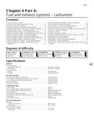
<strong>Engine</strong> <strong>electrical</strong> <strong>systems</strong> 5•5Never disconnect the battery terminals, oralternator multi-plug connector, when theengine is running.The battery leads and alternator multi-plugmust be disconnected before carrying out anyelectric welding on the car.Never use an ohmmeter of the typeincorporating a hand cranked generator forcircuit or continuity testing.Ignition and engine management<strong>systems</strong>Warning: The HT voltagegenerated by an electronicignition system is extremelyhigh, and in certaincircumstances could prove fatal. Take careto avoid receiving electric shocks from theHT side of the ignition system. Do nothandle HT leads, or touch the distributoror coil when the engine is running. Iftracing faults in the HT circuit, use wellinsulated tools to manipulate live leads.<strong>Engine</strong> management modules are verysensitive components, and certainprecautions must be taken to avoid damageto the module when working on a vehicleequipped with an engine management systemas follows.When carrying out welding operations onthe vehicle using electric welding equipment,the battery and alternator should bedisconnected.Although underbonnet-mounted modules(all except EEC IV) will tolerate normalunderbonnet conditions, they can beadversely affected by excess heat or moisture.If using welding equipment or pressurewashing equipment in the vicinity of themodule, take care not to direct heat, or jets ofwater or steam at the module. If this cannot beavoided, remove the module from the vehicle,and protect its wiring plug with a plastic bag.Before disconnecting any wiring, orremoving components, always ensure that theignition is switched off.On models with underbonnet-mountedmodules, do not run the engine with the moduledetached from the body panel, as the body actsas an effective heat sink, and the module maybe damaged due to internal overheating.Do not attempt to improvise fault diagnosisprocedures using a test lamp or multimeter,as irreparable damage could be caused to themodule.After working on ignition/enginemanagement system components, ensurethat all wiring is correctly reconnected beforereconnecting the battery or switching on theignition.On some early Bosch distributors it ispossible that with the distributor cap removed,if the engine is cranked, the cap securing clipsmay fall inward and jam the triggerwheel/vane, knocking it out of alignment. If thishappens, the distributor will have to berenewed as the trigger wheel/vane cannot berepositioned. Care should therefore be takennot to crank the engine with the distributor capremoved. Later distributors have redesignedclips which eliminate the problem.2 Battery - removal and refittingRemoval1 The battery is located in the enginecompartment on the left-hand side of thebulkhead.2 Disconnect the leads at the negative (earth)terminal by unscrewing the retaining nut andremoving the bulb. Pull off the plastic cover,and disconnect the positive terminal leads inthe same way.3 Unscrew the clamp bolt sufficiently toenable the battery to be lifted from its location(see illustration). Keep the battery in anupright position to avoid spilling electrolyte onthe bodywork.Refitting4 Refitting is a reversal of removal, but smearpetroleum jelly on the terminals whenreconnecting the leads, and always connectthe positive lead first and the negative lead last.3 Battery - testing and chargingTestingStandard and low maintenance battery1 If the vehicle covers a small annual mileageit is worthwhile checking the specific gravityof the electrolyte every three months todetermine the state of charge of the battery.Use a hydrometer to make the check andcompare the results with the following table.Ambient temperature:above 25ºC below 25ºCFully charged 1.21 to 1.23 1.27 to 1.2970% charged 1.17 to 1.19 1.23 to 1.25Fully discharged 1.05 to 1.07 1.11 to 1.13Note that the specific gravity readings assumean electrolyte temperature of 15ºC (60ºF); forevery 10ºC (50ºF) below 15ºC (60ºF) subtract0.007. For every 10ºC(50ºF) above 15ºC(60ºF)add 0.007.2 If the battery condition is suspect firstcheck the specific gravity of electrolyte ineach cell. A variation of 0.040 or morebetween any cells indicates loss of electrolyteor deterioration of the internal plates.3 If the specific gravity variation is 0.040 ormore, the battery should be renewed. If thecell variation is satisfactory but the battery isdischarged, it should be charged asdescribed later in this Section.Maintenance-free battery4 In cases where a “sealed-for-life”maintenance-free battery is fitted, topping-upand testing of the electrolyte in each cell is notpossible. The condition of the battery cantherefore only be tested using a batterycondition indicator or a voltmeter.5 If testing the battery using a voltmeter,connect the voltmeter across the battery andcompare the result with those given in theSpecifications under “charge condition”. Thetest is only accurate if the battery has notbeen subject to any kind of charge for theprevious six hours. If this is not the case,switch on the headlights for 30 seconds, thenwait four to five minutes before testing thebattery after switching off the headlights. Allother <strong>electrical</strong> components must be switchedoff, so check that the doors and tailgate arefully shut when making the test.6 If the voltage reading is less than 12.2 volts,then the battery is discharged, whilst areading of 12.2 to 12.4 volts indicates apartially discharged condition.7 If the battery is to be charged, first removeit from the vehicle.ChargingStandard and low maintenance battery8 Charge the battery at a rate of 3.5 to 4amps and continue to charge the battery atthis rate until no further rise in specific gravityis noted over a four hour period.9 Alternatively, a trickle charger charging at therate of 1.5 amps can be safely used overnight.10 Specially rapid “boost” charges which areclaimed to restore the power of the battery in1 to 2 hours are not recommended as theycan cause serious damage to the batteryplates through overheating.11 While charging the battery, note that thetemperature of the electrolyte should neverexceed 37.8ºC (100ºF).Maintenance-free battery12 This battery type takes considerablylonger to fully recharge than the standardtype, the time taken being dependent on theextent of discharge, but it can take anythingup to three days.13 A constant voltage type charger isrequired, to be set, when connected, to 13.9to 14.9 volts with a charger current below 25amps. Using this method the battery shouldbe useable within three hours, giving a voltagereading of 12.5 volts, but this is for a partiallydischarged battery and, as mentioned, fullcharging can take considerably longer.14 If the battery is to be charged from a fullydischarged state (condition reading less than12.2 volts) have it recharged by your <strong>Ford</strong>dealer or local automotive electrician as thecharge rate is higher and constant supervisionduring charging is necessary.2.3 Battery securing clamp and bolt5