installation and operating instructions for aq-1 and aq-2 power vent ...
installation and operating instructions for aq-1 and aq-2 power vent ...
installation and operating instructions for aq-1 and aq-2 power vent ...

You also want an ePaper? Increase the reach of your titles
YUMPU automatically turns print PDFs into web optimized ePapers that Google loves.
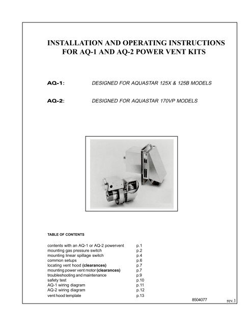
INSTALLATION AND OPERATING INSTRUCTIONSFOR AQ-1 AND AQ-2 POWER VENT KITSAQ-1:DESIGNED FOR AQUASTAR 125X & 125B MODELSAQ-2:DESIGNED FOR AQUASTAR 170VP MODELSTABLE OF CONTENTScontents with an AQ-1 or AQ-2 <strong>power</strong><strong>vent</strong> p.1mounting gas pressure switch p.2mounting linear spillage switch p.4common setups p.6locating <strong>vent</strong> hood (clearances) p.7mounting <strong>power</strong> <strong>vent</strong> motor (clearances) p.7troubleshooting <strong>and</strong> maintenance p.9safety test p.10AQ-1 wiring diagram p.11AQ-2 wiring diagram p.12<strong>vent</strong> hood template p.138504077rev.1
AQ-1 Power <strong>vent</strong> kit <strong>for</strong> Aquastar 125X &125B models.Parts includedSpillage Switch Kit1. 185º F linear spillage switch mounted on anangled bracket <strong>and</strong> equipped with 36 inchcables connected to one eyelet terminal<strong>and</strong> one 1/4" quick connect terminal2. Spillage switch mounting screw3. Push on male spade connector, replaceseyelet terminal from 36 inch spill switch cable.AQ-2 Power <strong>vent</strong> kit <strong>for</strong> Aquastar 170vpParts includedSpillage Switch Kit1. 185º F linear spillage switch mounted on anangled bracket <strong>and</strong> equipped with 36 inchcables connected to one eyelet terminal<strong>and</strong> one 1/4" quick connect terminal2. Spillage switch mounting screws (2)3. Capillary tube offset clips with mountingscrew 3 ea.Vent Hood Kit1. 4" <strong>vent</strong> hood: VH1-42. Plastic wall anchors (4)3. Sheet metal screws (4)4. 5" to 4" <strong>vent</strong> reducer pipeVent Hood Kit1. 4" <strong>vent</strong> hood: VH1-42. Plastic wall anchors (4)3. Sheet metal screws (4)Vibration Mount Packet1. Vibration mounts (2) with nuts <strong>and</strong> washers2. Brackets (2) with nuts <strong>and</strong> washersVibration Mount Packet1. Vibration mounts (2) with nuts <strong>and</strong> washers2. Brackets (2) with nuts <strong>and</strong> washersGas Pressure Switch Packet1. Gas pressure switch2. Self-tapping mounting screws (4)3. Manifold pressure tap fitting with 1/4" compressionnut <strong>and</strong> sleeve4. 1/4" by 40" aluminum tubing (2)Gas Pressure Switch Packet1. Gas pressure switch2. Self-tapping mounting screws (4)3. 1/8" NPT male by 1/4" compression fittingwith 1/4" compression nut <strong>and</strong> sleeve4. 1/4" by 40" aluminum tubing (2)Power Vent Kit1. Power <strong>vent</strong>er (HSUL-1 Series containingintegrated 24v control circuit) including 25foot control cable with 1/4" quick connectends <strong>and</strong> an HPN 6 foot <strong>power</strong> cord2. Nylon tiesPower Vent Kit1. Power <strong>vent</strong>er (HST-1 Series containingintegrated 24v control circuit <strong>and</strong> postpurge timer) including 25 foot control cablewith 1/4" quick connect ends <strong>and</strong> an HPN 6foot <strong>power</strong> cord2. Nylon ties1
Be<strong>for</strong>e beginning <strong>installation</strong> reviewrequired clearances <strong>for</strong> Aquastar,Power Vent Motor <strong>and</strong> Vent HoodPower Vent KitCAUTION1. Failure to install, maintain <strong>and</strong>/or operate thePower Venter in accordance withmanufacturer's instruction may result inconditions which can produce bodily injury <strong>and</strong>property damage.2. The Power Venter must be installed by <strong>aq</strong>ualified installer in accordance with all localcodes or, in their absence, in accordance withthe National Fuel Gas Code (ANSIZ223.1NFPA #54), the National Electric Code<strong>and</strong> The Occupational Health <strong>and</strong> Safety Act(OSHA) as applicable.3. The Power <strong>vent</strong>er motor shaft must bemounted horizontally to pre<strong>vent</strong> motor bearingwear.4. Disconnect <strong>power</strong> supply when making wiringconnections or when working around the fanblade <strong>and</strong> motor. Failure to do so may resultin severe personal injury <strong>and</strong> equipmentdamage.5. Make certain the <strong>power</strong> source is adequate <strong>for</strong>the fan motor requirements. Do not add the<strong>power</strong> <strong>vent</strong>er to a circuit where the total loadis unknown.Aquastar1. Follow <strong>installation</strong> <strong>and</strong> <strong>operating</strong> <strong>instructions</strong>manual supplied with the Aquastar.2. Be<strong>for</strong>e mounting water heater to wall, checkits minimum clearance requirements.3. When using an AQ-1 or AQ-2 the maximumhorizontal distance from Aquastar to dischargeis 100 feet. Subtract 10 feet <strong>for</strong> each addedelbow. Install <strong>power</strong> <strong>vent</strong>er motor as closeto the termination as possible to maintainthe Aquastar's optimal efficiency.FREEZING CONCERNS TO AQUASTAR:The <strong>vent</strong> hood <strong>and</strong> <strong>power</strong> <strong>vent</strong> will not pre<strong>vent</strong> infiltrationof cold air to the Aquastar when not in use.Be sure to correct any causes of negative air pressurein room. If this is difficult add additionalhorizontal lengths of 4" <strong>vent</strong> pipe between <strong>power</strong><strong>vent</strong> <strong>and</strong> the Aquastar to warm any infiltrating air.Gas Pressure SwitchRemove the gas pressure switch from the carton.Also remove the brass fittings (170vp: 1/8" NPT by1/4"compression fitting <strong>and</strong> nut), (125X/B models:manifold pressure tap fitting <strong>and</strong> 1/4" compressionnut). The four self-tapping screws <strong>and</strong> the two sectionsof 1/4" diameter aluminum tubing from themaster carton.The gas pressure switch is to be mounted in such away that the diaphragm is oriented vertically <strong>and</strong> thealuminum tubing pieces can easily reach the manifoldpressure test nipple <strong>and</strong> the burner respectively.It must not be mounted inside the heater. See p.6When mounting to an Aquastar 170vp: We recommendmounting on the lower right side of theAquastar. Both sides of the switch bracket can screwinto the side panel. Installed in this manner allnecessary connections will be well within reach <strong>and</strong>there should be minimal interference when servicing.The four screws provided are self-tapping. Their 1/2"length assure that components inside the Aquastar willnot be damaged upon penetration. You must notmount the switch where the screws could penetratethe heat exchanger tubing inside theAquastar.When mounting to Aquastar 125X/B models: Werecommend mounting the gas pressure switch verticallyagainst a wall on the lower left side of Aquastar125X/B models. Because the cabinet cover is threesided we do not recommend screwing the gas pressureswitch to the left side of it. Instead, mount the gaspressure switch vertically against a wall on the lower leftside of Aquastar 125X/B models. Installed in thismanner all necessary connections will be within reach<strong>and</strong> there will be minimal interference when servicing.See p.62
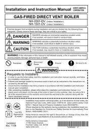
ROUTE TUBING TO PRESSURETAP PORT ON THEAQUASTAR BURNER MANIFOLD125X/B MODELSROUTE TUBING TO BURNERAREA OR ATMOSPHERIC VENTFIGURE AMANIFOLD TAPFIGURE BPRESSURE TAP-GAUGE PORT(WHERE AQUASTAR MANIFOLDPRESSURE CAN BE MEASURED)170VP MODELMANIFOLD TAPINSTRUCTIONS (SEE DIAGRAMS ABOVE)1. Mount gas pressure switch by securing it tothe chosen location with a screw in each oneof the four mounting holes.2. Use a tube cutter to make a clean cut (notcrimped) at each end of the two lengths of the1/4" aluminum tubing. One tube must be longenough to reach from the fitting marked"connect to gas valve" to the pressure tap porton the Aquastar burner manifold (Not to theinlet gas pressure port of the Aquastarsince there will be constant gas pressurethere). The second tube must be long enoughto reach from the gas pressure switch to theburner near (but not in) the pilot flame area.Allow enough slack <strong>for</strong> very gradual bends.(See Figure A).3. ATTENTION - Failure to follow the next seriesof <strong>instructions</strong> may result in breaking a part.a. Remove the brass pressure tap fitting fromthe burner manifold of the Aquastar. Observethe end of the fitting that screws into themanifold, notice that it is brass (soft metal).See Figure B. This fitting will not be required<strong>for</strong> reuse on 125X/B models.3b. On Aquastar 170vp model the pressuretap fitting has a brass hex cap. Separate thepressure tap fitting from the hex cap with twowrenches. See Figure B. Save the pressuretap fitting.c. Bend the 1/4" aluminum tubing so that itruns to where the fitting attaches to themanifold. Make gradual bends - do not crimpthe tube.d. On model Aquastar 170vp assemble the1/8" NPT male by 1/4" compression fittingwith nut <strong>and</strong> sleeve to aluminum tube. Tightenwith two wrenches.Do the same thing <strong>for</strong> Aquastar 125X/Bmodels with provided pressure tap fitting <strong>and</strong>1/4" compression nut with sleeve.e. Separate the joint just made in step 3.d.On Aquastar 170vp models connect the 1/8"NPT male by 1/4" compression fitting tomanifold pressure tap fitting as removed instep 3.a. Use an appropriate thread sealant.Snug up this joint while it is off the heater.
f. H<strong>and</strong> thread the pressure tap fitting (125X/B)or pressure tap fitting assembly (170vp) intothe Aquastar manifold. Use a small amountof an appropriate thread sealant <strong>for</strong> Aquastar125X/B models. Aquastar 170vp model has aflat washer that makes the seal <strong>for</strong> this joint soexcessive tightening is not necessary. Overtightening will break the pressure tapfitting.g. Guide the end of the tube into the compressionfitting. While using one wrench tohold back the pressure tap fitting, gently snugupthe compression nut with a second wrench.4. Bend the second piece of aluminum tubing(from step 2) so that it will reach from the gaspressure switch through the underneath of theAquastar to an area near the pilot head.Connect one end of the tube to the fittingmarked "warning" on the gas pressure switch.The other end of the tubing should now extendto burner area close to pilot. This tube shouldnot discharge into the flame nor should itextend above the upper edge of the burners.This tube <strong>vent</strong>s gas to the combustion chamber<strong>for</strong> ignition in case of a diaphragm failurein the gas pressure switch.NOTE: The gas pressure switch has a built inpressure tap marked "gauge port". Use thistap instead of the Aquastar manifold tap whenchecking manifold pressure. (See Figure A)Linear Spillage Sensing SwitchThis switch provides a means <strong>for</strong> safety shut down ofthe Aquastar in the e<strong>vent</strong> of flue blockage or <strong>power</strong><strong>vent</strong>er failure. If hot flue gasses spill from the draftdiverter, the draft spillage sensing switch will open thepilot safety circuit <strong>and</strong> shut off all gas to the Aquastar.The switch is normally closed <strong>and</strong> opens at temperaturesgreater than 185º F. It has a manual reset button.INSTRUCTIONS2. On Aquastar 170vp model the linear spillswitch should mount in a location where thetube can extend across the front of the draftdiverter while allowing the switch cables toeasily reach the overheat temperature sensor(ECO) connections. (See Figure C)On Aquastar 125X/B models the linear spillswitch should mount in a location where thetube can extend across the top of the draftdiverters while allowing the switch cables toreach the ECO. (See Figure D)3. Route the cables to the ECO switch inside theAquastar keeping the cables out of contactwith hot surfaces.SAFETY CIRCUITThe linear spill switch, when wired in series with theThermocouple <strong>and</strong> ECO of the Aquastar, <strong>for</strong>m theSafety Circuit. Aquastars have been manufacturedwith differing ECO locations. Depending on where theECO is in your Aquastar, you will need to followslightly different <strong>instructions</strong> <strong>for</strong> making the connections.1. On Aquastar 170vp models two ECO's aremounted on the left side of the heater,upper one is black <strong>and</strong> lower one is white.(See Figure C)a. Remove <strong>and</strong> discard heavy gauge wirefrom both upper <strong>and</strong> lower ECO's <strong>and</strong> attachone linear spill switch cable to upper ECOterminal <strong>and</strong> one to lower ECO.Note: remove the one 1/4" quick connectterminal <strong>and</strong> affix an eyelet terminal (notprovided) to make a secure connection ateither ECO that this cable is connecting to.On Aquastar model 170vp the copper capillarysensing tube should be attached across the front panelabove its large opening with the offset clips provided.See setup diagram on page 6.1. The entire length of the copper capillarysensing tube is heat sensitive. The idea is tosuspend the tube within close proximity of theAquastar's draft diverter. Offset clips areprovided <strong>for</strong> this purpose on model 170vp,not needed on 125X/B models. Note: do notcut the copper capillary sensing tube.4
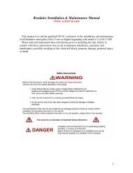
FIGURE CCONNECT THIS SPILL SWITCHLEAD TO ECO TERMINAL BYPUSHING IT ON OR CUTTING ANDREPLACING ITS END WITH ANEYELET TERMINAL.Aquastar 170vp ModelCONNECT SPILL SWITCHLEAD TO ECO TERMINALREMOVE HEAVYGAUGE WIRE FROMUPPER AND LOWERECO TERMINALS.3. On Aquastar 125X/B models the ECO ismounted on the lower left outlet waterpipe. (See figure D)a. Remove one lead connecting to ECOterminal, it does not matter which one isdisconnected.b. Attach 1/4" quick connect terminal end oflinear spill switch cable to now exposedterminal of the ECO.c. Remove the eyelet ended terminal fromthe other spill switch cable. Affix the push onmale spade connector, which is provided withthe AQ1, to this spill switch cable.d. Connect this male spade connector to theremoved lead wire from step 3.a.On Aquastar 125X/B models the linear spill switchshould be attached to the upper right-h<strong>and</strong> side on thedraft hood diverter (see figure E). There are two holesprovided <strong>for</strong> attachment on this diverter <strong>and</strong> only thefront most hole should need to be used. With the #12self tapping sheet metal screw securely mount thespill switch bracket to the diverter. For ease of accessposition it so the reset button faces outward <strong>and</strong> thenbend the bracket so the switch can st<strong>and</strong> vertically.The copper capillary sensing tube should then be directedto the left by looping it over the diverter opening,up in front of the 5" diameter <strong>vent</strong> pipe <strong>and</strong> then downacross the upper left h<strong>and</strong> draft diverter.FIGURE DECOFIGURE E125X/B ModelsDISCONNECT EITHER WIRE FROM ECO.PUSH ON ONE SPILL SWITCH LEAD CABLETO ECO AND OTHER (RETROFIT FIRST)INTO EITHER WIRE THAT WAS REMOVED.CAPILLARY SENSING TUBERESET BUTTONSPILL SWITCHCABLES5
COMMON SETUPSAquastar 170vp ModelLocation of Linear SpillageSwitch (Route Spillage SwitchCables behind back)125X & 125B ModelsMount gas pressureswitch against wallSee Figure E <strong>for</strong> location of Linear Spillage Switch6
NOTE: FOLLOW REQUIREMENTS IN FIGURES F & G ON THIS PAGE BEFOREINSTALLING VENT HOOD, THEN USE TEMPLATE ON PAGE 13 TO CUT HOLE.CAUTIONFailure to follow these <strong>installation</strong><strong>instructions</strong> may violate applicablenational <strong>and</strong>/or local codesThe <strong>vent</strong> system must terminate so that properclearances are maintained as cited in the National FuelGas Code, ANSI Z223.1"The exit terminals of mechanical <strong>vent</strong> system shall belocated not less than 7 feet above grade when locatedadjacent to a public walkway. The <strong>vent</strong>ing system shallterminate at least 3 feet above any <strong>for</strong>ced air inlet within 10feet. The <strong>vent</strong>ing system shall terminate at least 4 feetbelow, 4 feet horizontally from or 1 foot above any door,window or gravity air inlet into any building."Also, "The <strong>vent</strong> terminal shall also not be installed closerthan 3 feet from the inside corner of an L-shaped structure,or less than 1 foot above grade."FIGURE FPOWER VENT FAN AND MOTORCode RequirementsPower <strong>vent</strong> <strong>installation</strong> must be in accordance with thefollowing requirements of the National Fuel Gas Code:• All portions of the <strong>vent</strong> system under positivepressure during operations (on the outlet sideof the <strong>power</strong> <strong>vent</strong>er) shall be designed <strong>and</strong>installed so as to pre<strong>vent</strong> leakage of flue or<strong>vent</strong> gasses into building.• Provisions shall be made to interlock theappliance(s) to pre<strong>vent</strong> the flow of gas to themain burners when the draft system is notper<strong>for</strong>ming so as to satisfy the <strong>operating</strong>requirements of the equipment <strong>for</strong> safeper<strong>for</strong>mance.2. Power <strong>vent</strong>er must be mounted with motorshaft horizontal to pre<strong>vent</strong> motor bearingwear.3. Power <strong>vent</strong>er housing is single walled. A 6"clearance from combustible material must bemaintained. (See Figure G)4. Whenever possible, allow <strong>for</strong> a minimum of12" vertical rise off the top of the Aquastarbe<strong>for</strong>e the <strong>vent</strong> piping makes a 90º elbow tothe horizontal. Observing this guideline willhelp pre<strong>vent</strong> nuisance shut downs.FIGURE Gv6"vInstallation Restrictions1. Power <strong>vent</strong>er should be installed as close tothe termination of the <strong>vent</strong> system as possibleto obtain optimal appliance efficiency <strong>and</strong> topre<strong>vent</strong> flue gas leakage.v6"vv6"v7
INSTRUCTIONS(DO NOT BEGIN THESE PROCEDURESUNTIL VENT HOOD HAS BEEN IN-STALLED)1. Remove vibration mounts, nuts <strong>and</strong> washersfrom parts bag. Install on <strong>power</strong> <strong>vent</strong>er asshown in (Figure H).2. To pre<strong>vent</strong> vibration, securely support <strong>power</strong><strong>vent</strong>er from ceiling or joist using a plumber'sstrap or wire fastened to the vibration mounts.As an alternative means of support, a wallbracket may be used to support the undersideof the motor. (NOTE: Plumbers strap, wire orwall bracket must be supplied by installer.)6. Support the <strong>vent</strong> pipe in accordance with <strong>vent</strong>manufacturer's <strong>instructions</strong>. Vent pipe is notsupplied in the <strong>power</strong> <strong>vent</strong>er package, except<strong>for</strong> the 5" to 4" reducer <strong>vent</strong> pipe in the AQ-1.Observe the clearances associated with theclass of <strong>vent</strong> pipe used.FIGURE H3. Connect the <strong>power</strong> <strong>vent</strong>er outlet to the innersleeve of the <strong>vent</strong> hood. If you need to addsections of 4" Class B <strong>vent</strong> pipe between the<strong>power</strong> <strong>vent</strong>er <strong>and</strong> the <strong>vent</strong> hood, first check if itis permissable with local codes. Use the 4 prepunchedholes in the outlet collar of the <strong>power</strong><strong>vent</strong>er as a guide to drill 1/8" diameter holesinto the <strong>vent</strong> pipe. Fasten <strong>power</strong> <strong>vent</strong>er outletto the <strong>vent</strong> hood inlet using sheet metal screws.4. All <strong>vent</strong> pipe connections after the <strong>power</strong><strong>vent</strong>er will be under positive pressure duringoperation. These connections must be sealedwith high temperature silicone sealant oraluminum <strong>vent</strong> pipe tape supplied by theinstaller.5. Install properly sized <strong>vent</strong> pipe connectionsfrom the <strong>power</strong> <strong>vent</strong>er inlet to the Aquastar'soutlet avoiding elbows, wherever possible.Allow a minimum of 12" vertical rise off thetop of the Aquastar be<strong>for</strong>e the <strong>vent</strong> makes a90º elbow to the horizontal. Observe the <strong>vent</strong>pipe length restrictions mentioned earlier.NOTE: The AQ-1 provides a 5" to 4" reducer<strong>vent</strong> pipe which is applicable to Aquastar125X/B models only. The AQ-2 does notprovide a 6" to 4" reducer <strong>vent</strong> pipe <strong>and</strong> mustbe provided by the installer.Installation - Electrical1. Route the control cable from the <strong>power</strong> <strong>vent</strong>erfan along the ceiling or joists down to the gaspressure switch, taking care not to comecloser than 6" to the <strong>vent</strong> pipe or any otherpotentially hot surface. In many cases, thegas supply piping can be used as a routingpath from the ceiling down to the controls,using the supplied nylon ties to secure thecable.2. Connect the BLUE wire from the jacketed<strong>power</strong> <strong>vent</strong> cable onto the normally openterminal of the gas pressure switch.(See Figure I)8
FIGURE I3. Connect the RED wire from the jacketed cableonto the common terminal of the gas pressureswitch. (See Figure I)NOTE: If the distance between the <strong>power</strong><strong>vent</strong>er <strong>and</strong> the gas pressure switch isgreater than the length of the cable, splicea section of 2 conductor, PVC sheathed,105º C thermostat cable to the suppliedcable. Make sure that the colored leadsremain consistent.TROUBLE-SHOOTING, MAINTENANCEAND TEST PROCEDURESVent System MaintenanceThe <strong>vent</strong> system must be inspected at regular 3 monthintervals. Points of inspection are as follows:1. Screened opening of the <strong>vent</strong> hood should befree from <strong>for</strong>eign material <strong>and</strong> cleaned asnecessary.2. Check all <strong>vent</strong> system connections <strong>for</strong> leakage<strong>and</strong> reseal where needed. If any <strong>vent</strong>pipe shows signs of deterioration, replaceimmediately <strong>and</strong> check new connections <strong>for</strong>possible leaks. Reseal using General ElectricalRTV 106 Red HiTemp Silicone Sealer orequivalent.Gas Pressure Switch Test1. Follow the Aquastar <strong>operating</strong> <strong>instructions</strong>to light the pilot.2. Open a hot water outlet. This should energizethe <strong>power</strong> <strong>vent</strong> system. Next close the hotwater outlet to de-energize the <strong>vent</strong>er.3. Repeat step 2 to assure proper operation.4. If <strong>power</strong> <strong>vent</strong>er does not energize, check thatthe gas pressure switch tubes are properlyconnected <strong>and</strong> that the tube ends are notpinched closed.95. Make sure pressure switch is mounted in sucha way that the diaphragm is oriented vertically.Combustion Air Test1. Close all doors <strong>and</strong> windows of the building.If the Aquastar is installed in a utility room orcloset, close the entrance door to this room.Close fireplace dampers.2. Turn on any clothes dryers. Turn on allexhaust fans, such as a range hood, bathroom exhaust fans <strong>and</strong> whole house fans, tomaximum speeds. (Do not turn on any fansused strictly <strong>for</strong> summer exhausting).3. Open a hot water tap to full flow.4. Allow all fans <strong>and</strong> the Aquastar to operate <strong>for</strong>five (5) minutes.5. Tripping of the spillage switch circuit duringthe 5 minute Aquastar operation indicates anunsafe <strong>operating</strong> condition. Turn off gassupply to Aquastar <strong>and</strong> DO NOT OPERATEUNTIL UNSAFE VENTING CONDITION ISINVESTIGATED BY PROFESSIONALCONTRACTOR OR UTILITY SERVICEPERSONNEL.6. Return all windows, doors <strong>and</strong> fans to theirprevious condition of use.
SAFETY INTERLOCK TEST1. Open the gas supply to the Aquastar.2. Remove the <strong>vent</strong> pipe from the <strong>vent</strong> connectoron the top of the Aquastar.5. Per<strong>for</strong>m the operation circuit test <strong>and</strong> safetycircuit check. (See Safety Interlock Test)3. Block the <strong>vent</strong> connector with sheet metal orother noncombustible material.4. Turn on the hot water supply to allow theburner to activate. Hot flue gasses will spillfrom the draft diverter momentarily. In lessthan three (3) minutes, the linear spillageswitch should trip, opening the electric circuitto the electromagnet valve <strong>and</strong> halting theflow of gas to the burner.NOTE: If spillage switch does not shut off thegas, check that you have made the propersafety circuit connections. If the switch stilldoes not trip, contact Controlled EnergyCorporation at 800 642 3111 or TjernlundProducts at 800 255 4208.5. After the burners shut off, turn off hot watersupply <strong>and</strong> wait 2-3 minutes...then push thereset button on the linear spillage switch.CAUTION: If <strong>for</strong> any reason the systemhas shut down during operation, the causeof the system failure should be investigated<strong>and</strong> corrected be<strong>for</strong>e resetting the safetyswitches <strong>and</strong> lighting the pilot.If you have any questions with regard to this <strong>installation</strong>,please call Controlled Energy at 800 642 3111 orTjernlund Products at 800 255 4208.6. Light pilot on Aquastar <strong>and</strong> repeat SafetyInterlock Test, (Step 1-5)7. Reconnect the <strong>vent</strong> pipe to the <strong>vent</strong>ingsystem when complete.CAUTION: Metal <strong>vent</strong> pipe <strong>and</strong> <strong>vent</strong>blockage metal will be hot.In the E<strong>vent</strong> of Pilot Outage1. Push the reset button located in the center ofthe linear spillage sensing switch.2. Verify that there is 115V <strong>power</strong> provided to thePower Venter. This can be done by checkingthe circuit breaker <strong>and</strong> electrical connections.3. Visually verify that all the connections of thecontrol cord circuit are intact.4. Follow Aquastar <strong>installation</strong> <strong>and</strong> <strong>operating</strong><strong>instructions</strong> <strong>for</strong> relighting the Aquastar.10
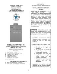
AQUASTAR SAFETY INTERLOCK DIAGRAMECO11
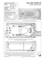
AQUASTAR SAFETY INTERLOCK DIAGRAMUPPER ECOLOWER ECO12
1. Attach this template to the interior of the wallthe Vent Hood will be penetrating.2. Ensure that proposed <strong>vent</strong> termination clearancesare met be<strong>for</strong>e cutting opening throughwall. Using a 1/2" drill bit, drill two pilot holeswhere noted on this template. The drill bit mustbe long enough to penetrate to the buildingexterior.3. Attach this template to the building exterioraligning the pilot holes on the template withthe pilot holes drilled in step 2.4. Using a reciprocating saw, cut a hole throughthe building siding, wall board, etc., followingthe appropriate lines of this template.5. Slide the <strong>vent</strong> hood through the opening <strong>and</strong>fasten to exterior wall using provided screws.6. Once Power Venter is completely installed <strong>and</strong>secured, apply a bead of exterior rated caulkbetween Vent Hood flange <strong>and</strong> exterior ofbuilding.VH1-4 (SQUARE) VENT HOOD INSTALLATION TEMPLATECUT HOLE THROUGH WALLTEMPLATEPILOTHOLEPILOTHOLEBUILDINGEXTERIORWASHER (4)SHEET METAL SCREW (4)NOTE: HARDWARE SHOWN INCLUDEDWITH VENT HOOD13