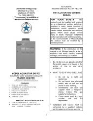
installation and operating instructions for aq-1 and aq-2 power vent ...
installation and operating instructions for aq-1 and aq-2 power vent ...
installation and operating instructions for aq-1 and aq-2 power vent ...

You also want an ePaper? Increase the reach of your titles
YUMPU automatically turns print PDFs into web optimized ePapers that Google loves.
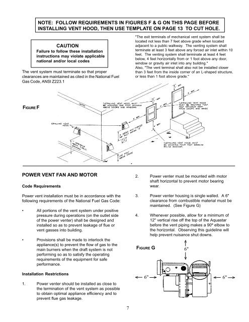
NOTE: FOLLOW REQUIREMENTS IN FIGURES F & G ON THIS PAGE BEFOREINSTALLING VENT HOOD, THEN USE TEMPLATE ON PAGE 13 TO CUT HOLE.CAUTIONFailure to follow these <strong>installation</strong><strong>instructions</strong> may violate applicablenational <strong>and</strong>/or local codesThe <strong>vent</strong> system must terminate so that properclearances are maintained as cited in the National FuelGas Code, ANSI Z223.1"The exit terminals of mechanical <strong>vent</strong> system shall belocated not less than 7 feet above grade when locatedadjacent to a public walkway. The <strong>vent</strong>ing system shallterminate at least 3 feet above any <strong>for</strong>ced air inlet within 10feet. The <strong>vent</strong>ing system shall terminate at least 4 feetbelow, 4 feet horizontally from or 1 foot above any door,window or gravity air inlet into any building."Also, "The <strong>vent</strong> terminal shall also not be installed closerthan 3 feet from the inside corner of an L-shaped structure,or less than 1 foot above grade."FIGURE FPOWER VENT FAN AND MOTORCode RequirementsPower <strong>vent</strong> <strong>installation</strong> must be in accordance with thefollowing requirements of the National Fuel Gas Code:• All portions of the <strong>vent</strong> system under positivepressure during operations (on the outlet sideof the <strong>power</strong> <strong>vent</strong>er) shall be designed <strong>and</strong>installed so as to pre<strong>vent</strong> leakage of flue or<strong>vent</strong> gasses into building.• Provisions shall be made to interlock theappliance(s) to pre<strong>vent</strong> the flow of gas to themain burners when the draft system is notper<strong>for</strong>ming so as to satisfy the <strong>operating</strong>requirements of the equipment <strong>for</strong> safeper<strong>for</strong>mance.2. Power <strong>vent</strong>er must be mounted with motorshaft horizontal to pre<strong>vent</strong> motor bearingwear.3. Power <strong>vent</strong>er housing is single walled. A 6"clearance from combustible material must bemaintained. (See Figure G)4. Whenever possible, allow <strong>for</strong> a minimum of12" vertical rise off the top of the Aquastarbe<strong>for</strong>e the <strong>vent</strong> piping makes a 90º elbow tothe horizontal. Observing this guideline willhelp pre<strong>vent</strong> nuisance shut downs.FIGURE Gv6"vInstallation Restrictions1. Power <strong>vent</strong>er should be installed as close tothe termination of the <strong>vent</strong> system as possibleto obtain optimal appliance efficiency <strong>and</strong> topre<strong>vent</strong> flue gas leakage.v6"vv6"v7