
Create successful ePaper yourself
Turn your PDF publications into a flip-book with our unique Google optimized e-Paper software.
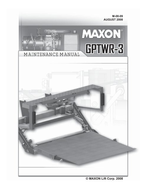
M-08-09AUGUST <strong>2008</strong>MAINTENANCE MANUAL© MAXON Lift Corp. <strong>2008</strong>
LIFT CORP.11921 Slauson Ave.Santa Fe Springs, CA. 90670CUSTOMER SERVICE:TELEPHONE (562) 464-0099 TOLL FREE (800) 227-4116FAX: (888) 771-7713NOTE: For latest version of all Manuals (and replacements), download theManuals from <strong>Maxon</strong>’s website at www.maxonlift.com.WARRANTY/ RMA POLICY & PROCEDURELIFTGATE WARRANTYType of Warranty:Term of Warranty:Full Parts and LaborStandard Liftgates - 2 years from ship date or 6,000 cyclesPremium Liftgates - 2 years from ship date or 10,000 cyclesThis warranty shall not apply unless the product is installed, operated and maintained in accordance with MAXON Lift’s specifi cations as set forth inMAXON Lift’s Installation, Operation and Maintenance manuals. This warranty does not cover normal wear, maintenance or adjustments, damage ormalfunction caused by improper handling, installation, abuse, misuse, negligence, or carelessness of operation. In addition, this warranty does notcover equipment that has had unauthorized modifi cations or alterations made to the product.MAXON agrees to replace any components which are found to be defective during the fi rst 2 years of service, and will reimburse for labor based onMAXON’s Liftgate Warranty Flat Rate Schedule. (Copy of the Flat Rate is available at www.maxonlift.com.)All warranty repairs must be performed by an authorized MAXON warranty facility. For any repairs that may exceed $500, including parts and labor,MAXON’s Technical Service Department must be notifi ed and an “Authorization Number” obtained.All claims for warranty must be received within 30 Days of the repair date, and include the following information:1. Liftgate Model Number and Serial Number2. The End User must be referenced on the claim3. Detailed Description of Problem4. Corrective Action Taken, and Date of Repair5. Parts used for Repair, Including MAXON Part Number(s)6. MAXON R.M.A. # and/or Authorization # if applicable (see below)7. Person contacted at MAXON if applicable8. Claim must show detailed information i.e. Labor rate and hours of work performedWarranty claims can also be placed online at www.maxonlift.com. Online claims will be given priority processing.All claims for warranty will be denied if paperwork has not been received or claim submitted via <strong>Maxon</strong> website for processing by MAXON’s WarrantyDepartment within 30 days of repair date.All components may be subject to return for inspection, prior to the claim being processed. MAXON products may not be returned without prior writtenapproval from MAXON’s Technical Service Department. Returns must be accompanied by a copy of the original invoice or reference with originalinvoice number and are subject to a credit deduction to cover handling charges and any necessary reconditioning costs. Unauthorized returns will berefused and will become the responsibility of the returnee.Any goods being returned to MAXON Lift must be pre-approved for return, and have the R.M.A. number written on the outside of the package in plainview, and returned freight prepaid. All returns are subject to a 15% handling charge if not accompanied by a detailed packing list. Returned partsare subject to no credit and returned back to the customer. Defective parts requested for return must be returned within 30 days of the claim date forconsideration to:MAXON Lift Corp.10321 Greenleaf Ave., Santa Fe Springs, CA 90670Attn: RMA#__MAXON’s warranty policy does not include the reimbursement for travel time, towing, vehicle rental, service calls, oil, batteries or loss of income due todowntime. Fabrication or use of non <strong>Maxon</strong> parts, which are available from MAXON, are also not covered.MAXON’s Flat Rate Labor Schedule takes into consideration the time required for diagnosis of a problem.All Liftgates returned are subject to inspection and a 15% restocking fee. Any returned Liftgates or components that have been installed or not returnedin new condition will be subject to an additional reworking charge, which will be based upon the labor and material cost required to return the Liftgate orcomponent to new condition.PURCHASE PART WARRANTYTerm of Warranty: 1 Year from Date of Purchase.Type of Warranty: Part replacement only. MAXON will guarantee all returned genuine MAXON replacement parts upon receipt and inspection of partsand original invoice.All warranty replacements parts will be sent out via ground freight. If a rush shipment is requested, all freight charges will be billed to the requestingparty.
TABLE OF CONTENTSWARNINGS ........................................................................................................................... 6SAFETY INSTRUCTIONS .................................................................................................... 6LIFTGATE TERMINOLOGY .................................................................................................. 9PERIODIC MAINTENANCE ................................................................................................ 10PERIODIC MAINTENANCE CHECKS ................................................................................ 10PERIODIC MAINTENANCE CHECKLIST ............................................................................11CHECKING HYDRAULIC FLUID ........................................................................................ 12CHANGING HYDRAULIC FLUID ........................................................................................ 14REPLACING PLATFORM TORSION SPRING ................................................................... 16PLATFORM ADJUSTMENT ................................................................................................ 17PARTS BREAKDOWN ....................................................................................................... 19MAIN ASSEMBLY (ALUMINUM PLATFORM) ..................................................................... 19EXTENSION PLATE ASSEMBLY ........................................................................................ 20MAIN FRAME ASSEMBLY .................................................................................................. 22PLATFORM & FLIPOVER ASSEMBLY (ALUMINUM)......................................................... 26PLATFORM & FLIPOVER ASSEMBLY WITH CART STOPS (ALUMINUM)....................... 27PLATFORM ASSEMBLY (ALUMINUM)............................................................................... 28FLIPOVER WITH SINGLE CART STOP (ALUMINUM) ...................................................... 30FLIPOVER WITH DUAL CART STOPS (ALUMINUM)........................................................ 32DOCK BUMPER .................................................................................................................. 34PUMP ASSEMBLY .............................................................................................................. 35HYDRAULIC COMPONENTS - POWER DOWN ................................................................ 3612 VDC POWER UNIT ........................................................................................................ 38CONTROL SWITCH AND POWER CABLE ........................................................................ 41DECALS .............................................................................................................................. 42
SYSTEM DIAGRAMS ......................................................................................................... 45PUMP & MOTOR SOLENOID OPERATION ....................................................................... 45HYDRAULIC SCHEMATIC (POWER DOWN) .................................................................... 46ELECTRICAL SCHEMATIC (POWER DOWN) ................................................................... 47TROUBLESHOOTING ........................................................................................................ 48PLATFORM WILL NOT RAISE & MOTOR WILL NOT RUN ............................................... 48PLATFORM WILL NOT RAISE, BUT MOTOR RUNS ......................................................... 49PLATFORM RAISES BUT LEAKS DOWN .......................................................................... 50PLATFORM RAISES PARTIALLY AND STOPS .................................................................. 52LIFTGATE WILL NOT LIFT RATED CAPACITY .................................................................. 53PLATFORM RAISES SLOWLY ........................................................................................... 54PLATFORM WILL NOT LOWER, LOWERS TOO SLOWLY OR TOO QUICKLY ................ 56PLATFORM BEGINS TO LOWER ON LH SIDE, BUT WILL NOT LOWER ON RH SIDE .. 58PLATFORM WILL NOT TILT DOWN TO THE GROUND .................................................... 61
Comply with the following WARNINGS and SAFETY INSTRUCTIONS while maintainingLiftgates. See Operation Manual for operating safety requirements.WARNINGS!WARNING• Do not stand, or allow obstructions, under the platform when lowering the Liftgate. Be sure yourfeet are clear of the Liftgate.• Keep fingers, hands, arms, legs, and feet clear of moving Liftgate parts (and platformedges) when operating the Liftgate.• Correctly stow platform when not in use. Extended platforms could create a hazard forpeople and vehicles passing by.11921 Slauson Ave. Santa Fe Springs, CA. 90670 (800) 227-4116 FAX (888) 771-7713• Disconnect Liftgate power cable from battery before repairing or servicing Liftgate.• If it is necessary to stand on the platform while maintaining the Liftgate, keep your feet and anyobjects clear of the inboard edge of the platform. Your feet or objects on the platform can becometrapped between the platform and the Liftgate extension plate.• Recommended practices for welding on steel parts are contained in the current AWS (AmericanWelding Society) D1.1 Structural Welding Code - Steel. Damage to Liftgate and/or vehicle, andpersonal injury could result from welds that are done incorrectly.• Recommended practices for welding on aluminum parts are contained in the current AWS(American Welding Society) D2.1 Structural Welding Code - Aluminum. Damage to Liftgateand/or vehicle, and personal injury could result from welds that are done incorrectly.SAFETY INSTRUCTIONSSAFETY INSTRUCTIONS• Read and understand the instructions in this Maintenance Manual before performing maintenanceon the Liftgate.• Before operating the Liftgate, read and understand the operating instructions in OperationManual.• Comply with all WARNING and instruction decals attached to the Liftgate.• Keep decals clean and legible. If decals are illegible or missing, replace them. Free replacementdecals are available from <strong>Maxon</strong> Customer Service.• Consider the safety and location of bystanders and location of nearby objects when operating theLiftgate. Stand to one side of the platform while operating the Liftgate• Do not allow untrained persons to operate the Liftgate.• Wear appropriate safety equipment such as protective eyeglasses, faceshield and clothing whileperforming maintenance on the Liftgate and handling the battery. Debris from drilling and contactwith battery acid may injure unprotected eyes and skin.• Be careful working by an automotive type battery. Make sure the work area is well ventilated andthere are no fl ames or sparks near the battery. Never lay objects on the battery that can short theterminals together. If battery acid gets in your eyes, immediately seek fi rst aid. If acid gets on yourskin, immediately wash it off with soap and water.6
• If an emergency situation arises (vehicle or Liftgate) while operating the Liftgate, release the controlswitch to stop the Liftgate.• A correctly installed Liftgate operates smoothly and reasonably quiet. The only noticeable noiseduring operation comes from the power unit while the platform is raised. Listen for scraping, gratingand binding noises and correct the problem before continuing to operate Liftgate.• Use only <strong>Maxon</strong> Authorized Parts for replacement parts. Provide Liftgate model and serial numberinformation with your parts order. Order replacement parts from:MAXON LIFT CORP. Customer Service11921 Slauson Ave., Santa Fe Springs, CA 90670Online: www.maxonlift.comExpress Parts Ordering: Phone (800) 227-4116 ext. 4345Email: Ask your Customer Service representative11921 Slauson Ave. Santa Fe Springs, CA. 90670 (800) 227-4116 FAX (888) 771-77137
11921 Slauson Ave. Santa Fe Springs, CA. 90670 (800) 227-4116 FAX (888) 771-7713THIS PAGE INTENTIONALLY LEFT BLANK8
LIFTGATE TERMINOLOGYDOCKBUMPERPLATFORMLIFTCYLINDEREXTENSIONPLATEPARALLELARMWEDGE FLIPOVERICCBUMPERRAMP BOXMAINFRAMECONTROLSWITCHTORSIONSPRINGPLATFORMOPENERLIFTARMPUMPBOXHYDRAULICLOCK11921 Slauson Ave. Santa Fe Springs, CA. 90670 (800) 227-4116 FAX (888) 771-77139
PERIODIC MAINTENANCEPERIODIC MAINTENANCE CHECKS!WARNINGNever operate the Liftgate if parts are loose or missing.11921 Slauson Ave. Santa Fe Springs, CA. 90670 (800) 227-4116 FAX (888) 771-7713NOTE: Make sure vehicle is parked on level ground while performing themaintenance checks.Quarterly or 1250 Cycles (whichever occurs first)Check the hydraulic fl uid level in the pump reservoir. Refer to the CHECKING HYDRAULICFLUID procedure in the PERIODIC MAINTENANCE section.If hydraulic fl uid appears contaminated, refer to the CHANGING HYDRAULIC FLUIDprocedure in the PERIODIC MAINTENANCE section.Keep track of the grade of hydraulic fl uid in the pump reservoir and never mix two differentgrades of fl uid.Check all hoses and fi ttings for chafi ng and fl uid leaks. Tighten loose fi ttings or replaceparts as required.Check electrical wiring for chafi ng and make sure wiring connections are tight and free ofcorrosion. Use dielectric grease to protect electrical connections.Check that all WARNING and instruction decals are in place. Also, make sure decals arelegible, clean and undamaged.Check that all bolts, nuts, and roll pins are in place. Make sure roll pins protrude evenlyfrom both sides of hinge pin collar. Replace fasteners and roll pins if necessary.CAUTIONDamaged cylinder seals and contaminated hydraulic fluid can result from paintingthe polished portion of the cylinder rod. To prevent damage, protect theexposed polished portion of the cylinder rod while painting.Check for rust and oily surfaces on Liftgate. If there is rust or oil on Liftgate, clean it off.Touch up the paint where bare metal is showing. MAXON recommends using the aluminumprimer touchup paint kit, P/N 908119-01.Semi-annually or 2500 Cycles (whichever occurs first)Visually check the platform hinge pins for excessive wear and broken welds. See PARTSBREAKDOWN section for replacement parts. Also, do the Quarterly or 1250 Cyclesmaintenance checks.10
PERIODIC MAINTENANCE CHECKLISTNOTE: Make sure vehicle is parked on level ground while performing maintenancechecks.Quarterly or 1250 Cycles (whichever occurs first)Check the level and condition of the hydraulic fl uid.Visually check all hoses and fi ttings for chafi ng and fl uid leaks. Tighten loose fi ttings orreplace parts as required.Check electrical wiring for chafi ng and make sure wiring connections are tight and freeof corrosion. Use dielectric grease to protect electrical connections.Check that all WARNING and instruction decals are in place. Also, make sure decalsare legible, clean, and undamaged.Check that all bolts, nuts, and roll pins are in place. Make sure roll pins protrude evenlyfrom both sides of hinge pin collar. Replace fasteners and roll pins if necessary.Check for rust and oily surfaces on Liftgate. If there is rust or oil on Liftgate or if theLiftgate is dirty, clean it off. Touch up the paint where bare metal is showing. Refer tothe paint system CAUTION and recommended touchup kit on the preceding page.Semi-annually or 2500 Cycles (whichever occurs first)Visually check the platform hinge pins for excessive wear and broken welds.Do the Quarterly or 1250 Cycles Checks on this checklist.11921 Slauson Ave. Santa Fe Springs, CA. 90670 (800) 227-4116 FAX (888) 771-771311
PERIODIC MAINTENANCECHECKING HYDRAULIC FLUIDCAUTIONKeep dirt, water and other contaminants from entering the hydraulic system.Before opening the hydraulic fluid reservoir filler cap, drain plug and hydrauliclines, clean up contaminants that can get in the openings. Also, protect theopenings from accidental contamination.NOTE: Use correct grade of hydraulic fl uid for your location.11921 Slauson Ave. Santa Fe Springs, CA. 90670 (800) 227-4116 FAX (888) 771-7713+50 to +120 Degrees F - Grade ISO 32Below + 70 Degrees F - Grade ISO 15 or MIL-H-5606See TABLES 13-1 & 13-2 for recommended brands.1. Unbolt and remove pump cover(FIG. 12-1).2. Check the hydraulic fl uid level inreservoir as follows. With Liftgatestowed, or platform at vehicle bedheight, level should be as shown inFIG. 12-2.NOTE: If the hydraulic fl uid in thereservoir is contaminated, dothe CHANGING HYDRAULICFLUID procedure in this section.3. If needed, add fl uid to the reservoir as follows.Pull out (no threads) fi ller cap (FIG.12-2). Fill the reservoir with hydraulic fl uiduntil reservoir looks about half full (FIG. 12-2). Reinstall fi ller cap (FIG. 12-2).CAUTIONPump cover must be correctly securedto prevent it from becominga hazard. To secure pump cover,the long side of the holder flatsmust butt against pump cover asshown in the illustration.4. Bolt on the pump cover as shown inFIG. 12-1. Torque the 5/16”-18 coverbolts from 10 to 14 lb-ft.POWERUNIT(REF)HEX NUTS(2 PLACES)FLATWASHERS(2 PLACES)PUMPCOVERLONG SIDE OFHOLDER FLATSBUTT AGAINSTCOVERCAP SCREWS(2 PLACES)UNBOLTING / BOLTING PUMP COVERFIG. 12-1FILLERCAPPOWER UNIT FLUID LEVELFIG. 12-2RESERVOIRHALFFULL12
ISO 32 HYDRAULIC OILRECOMMENDEDBRANDSPART NUMBERAMSOILAWH-05CHEVRON HIPERSYN 32KENDALLGOLDEN MVSHELL TELLUS T-32EXXON UNIVIS N-32MOBILTABLE 13-1TABLE 13-2DTE-13M, DTE-24,HYDRAULIC OIL-13ISO 15 OR MIL-H-5606 HYDRAULIC OILRECOMMENDEDBRANDSPART NUMBERAMSOILAWF-05CHEVRONFLUID A, AW-MV-15KENDALLGLACIAL BLUSHELL TELLUS T-15EXXONUNIVIS HVI-13MOBILDTE-11MROSEMEAD THS FLUID 1711111921 Slauson Ave. Santa Fe Springs, CA. 90670 (800) 227-4116 FAX (888) 771-771313
PERIODIC MAINTENANCECHANGING HYDRAULIC FLUIDCAUTIONKeep dirt, water and other contaminants from entering the hydraulic system.Before opening the hydraulic fluid reservoir filler cap, drain plug and hydrauliclines, clean up contaminants that can get in the openings. Also, protect theopenings from accidental contamination.11921 Slauson Ave. Santa Fe Springs, CA. 90670 (800) 227-4116 FAX (888) 771-7713NOTE: Use correct grade of hydraulic fl uid for your location.+50 to +120 Degrees F - Grade ISO 32Below + 70 Degrees F - Grade ISO 15 or MIL-H-5606See TABLES 13-1 & 13-2 for recommended brands.1. Unbolt and remove pump cover(FIG. 14-1). Place empty 5gallon bucket under drain plug(FIG. 14-2).2. Open and raise platform to vehicle bedheight. Pull out (no threads) drain plug(FIG. 14-2). Drain hydraulic fl uid.POWERUNIT(REF)HEX NUTS(2 PLACES) FLATWASHERS(2 PLACES)PUMPCOVERUNBOLTING PUMP COVERFIG. 14-1POWER UNITFIG. 14-2LONG SIDE OFHOLDER FLATSBUTT AGAINSTCOVERCAP SCREWS(2 PLACES)DRAIN PLUG14
NOTE: MAXON recommends usingdielectric grease on all electricalconnections.3. Disconnect the white wire (FIG. 15-1) fromstarter solenoid. Lower the platform whiledraining the remaining hydraulic fl uid fromsystem. Reinstall drain plug. Reconnect thewhite wire to starter solenoid.4. Pull out (no threads) fi ller cap (FIG.15-2). Add 1 gallon of hydraulic fl uidto reservoir. The reservoir should lookabout half full (FIG. 15-2). Reinstallfi ller cap (FIG. 15-2).5. Stow the lift and do the CHECKINGHYDRAULIC FLUID procedure in thissection of the manual.CAUTIONPump cover must be correctly securedto prevent it from becominga hazard. To secure pump cover,the long side of the holder flatsmust butt against pump cover asshown in the illustration.HEXNUTDISCONNECTING WHITE WIREFIG. 15-1POWERUNIT(REF)FILLERCAPPOWER UNITFIG. 15-2STARTERSOLENOIDWHITEWIRERESERVOIRDRAIN PLUGHALFFULLLONG SIDE OFHOLDER FLATSBUTT AGAINSTCOVER11921 Slauson Ave. Santa Fe Springs, CA. 90670 (800) 227-4116 FAX (888) 771-77136. Bolt on the pump cover as shown inFIG. 15-3. Torque the 5/16”-18 coverbolts from 10 to 14 lb-ft.HEX NUTS(2 PLACES) FLATWASHERS(2 PLACES)PUMPCOVERCAP SCREWS(2 PLACES)BOLTING ON PUMP COVERFIG. 15-315
PERIODIC MAINTENANCEREPLACING PLATFORM TORSION SPRINGNOTE: The following procedure shows how to replace torsion spring on RH side ofplatform. Use this procedure for replacing torsion spring on the LH side.11921 Slauson Ave. Santa Fe Springs, CA. 90670 (800) 227-4116 FAX (888) 771-77131. Manually fold fl ipover onto platform.2. Raise platform to a convenient work heightto gain access and release tension on thetorsion spring.!CAUTIONTo prevent injury and equipmentdamage, make sure there is notension on torsion spring beforeremoving hinge pin.3. Unbolt hinge pin from hinge bracket(FIG. 16-1). Remove bolt and lock nut.Drive the hinge pin inboard toward theshackle with a hammer and pin punch,just enough to free the torsion spring(FIG. 16-1). Remove spring from shackle.4. Install the torsion spring as shown inFIG. 16-2. Make sure the long legof the spring is inserted in the bracketlocated on shackle (FIG. 16-2). Makesure the short end of the spring is visibleand resting against the edge of thehinge bracket (FIG. 16-2).5. Drive the hinge pin into correct position(FIG. 16-2) through the hingebracket with a hammer and pinpunch. Line up the bolt hole in thehinge pin with the hole in the hingebracket. Bolt the hinge pin to hingebracket with bolt and lock nut (FIG.16-2).6. Operate the Liftgate to makesure it operates correctly.PLATFORM(REFERENCE)BOLTPLATFORM(REFERENCE)BOLT &LOCK NUTSHORTLEGHINGE PINLOCKNUTFIG. 16-1HINGE PINTORSIONSPRINGLONGLEGFIG. 16-2BRACKETHINGEBRACKETSHACKLEHINGEBRACKETSHACKLE16
PLATFORM ADJUSTMENTNOTE: Before doing the following procedure,make sure vehicle is parkedon level ground.1. With the platform and fl ipover unfolded,raise platform to bed level (FIG. 17-1).Measure how much the outboard edgeof platform rises above bed level (FIG.17-1). The outboard edge can be amaximum of 2” above bed level if bedheight is 48” to 53”. If bed height is 54”to 55” the outboard edge be level (FIG.17-1). If indication is correct, Liftgate isinstalled correctly and no adjustment isneeded. If the outboard edge is below bedlevel, do instructions 2, 3, and 6. If outboardedge is higher than 2”, do instructions4 through 6.2. Compare measurement “A” (FIG.17-2) with the distances and shimsin TABLE 17-1. For example: Ifmeasurement “A” (FIG. 17-2) is1” below level and you want to raiseoutboard edge of platform 1” abovelevel, use 1/8” shim to raise 2”(TABLE 17-1).RAISE PLATFORMEDGE (OUTBOARD)THIS DISTANCE (“A”)REQUIRED SHIMTHICKNESSWELD SIZE“W”1” 1/16” 1/16”2” 1/8” 1/8”3” 3/16” 3/16”4” 1/4” 1/4”“A”OUTBOARD EDGE2” MAX (48”-53” BED HT.0” LEVEL (54”-55” BED HT.)LEVEL LINELEVEL LINEPLATFORM EDGE AT ORABOVE BED LEVELFIG. 17-1PLATFORM EDGE BELOW BED LEVELFIG. 17-2SHACKLE(REF)EXTENSIONPLATE (REF)EXTENSIONPLATE (REF)VEHICLEFLOOR (REF)VEHICLEFLOOR (REF)11921 Slauson Ave. Santa Fe Springs, CA. 90670 (800) 227-4116 FAX (888) 771-7713TABLE 17-13. Weld shims (parts bag item) on bothplatform stops (FIG. 17-3) to raiseoutboard edge of platform to correctposition.17NEW SHIM(TABLE 17-1)2 PLACES“W”(TABLE 17-1)WELDING SHIMS (CURBSIDE SHOWN)FIG. 17-3
PLATFORM ADJUSTMENT - Continued11921 Slauson Ave. Santa Fe Springs, CA. 90670 (800) 227-4116 FAX (888) 771-77134. Compare measurement “B” (FIG.18-1) with the distances and grindingdepths in TABLE 18-1. For example:If measurement “B” (FIG. 18-1) is 3”above bed level and you want to lowerthe outboard edge of platform to 1”above bed level, grind 1/8” from eachplatform stop (TABLE 18-1).LOWER PLATFORMEDGE (OUTBOARD)THIS DISTANCE(“B”)GRIND METALFROM PLATFORMSTOP1” 1/16”2” 1/8”3” 3/16”4” 1/4”TABLE 18-15. Grind metal from platform stops (FIG.18-2) to lower outboard edge of platformto correct position.6. Lower the platform, then raise it to bedlevel. The outboard edge of platform shouldbe level or up to 2” maximum above bedlevel (FIG. 18-3).“B”LEVEL LINEPLATFORM EDGE ABOVE BED LEVELFIG. 18-1SHACKLE(REF)GRIND THIS FACE(SEE TABLE 18-1)GRINDING PLATFORM STOPS(CURBSIDE SHOWN)FIG. 18-2OUTBOARD EDGE2” MAX (48”-53” BED HT.0” LEVEL (54”-55” BED HT.)LEVEL LINEEXTENSIONPLATE (REF)VEHICLEFLOOR (REF)EXTENSIONPLATE (REF)VEHICLEFLOOR (REF)PLATFORM EDGE ABOVE BED LEVELFIG. 18-318
PARTS BREAKDOWNMAIN ASSEMBLY (ALUMINUM PLATFORM)REFER TO EXTENSIONPLATE ASSEMBLYREFER TO MAINFRAME ASSEMBLY1REFER TO PLATFORM &FLIPOVER ASSEMBLYREFER TO HYDRAULICCOMPONENTS & PUMPCOVER & MOUNTINGPLATE ASSEMBLY211921 Slauson Ave. Santa Fe Springs, CA. 90670 (800) 227-4116 FAX (888) 771-7713ITEM QTY. PART NO. DESCRIPTION1 1 265743 CHANNEL, 3” X 4” X 67” LG. (ICC BUMPER)2 2 264209 ANGLE, 2” X 2” X 1/4” X 14” LG. (ICC BUMPER)19
EXTENSION PLATE ASSEMBLY11921 Slauson Ave. Santa Fe Springs, CA. 90670 (800) 227-4116 FAX (888) 771-7713116938(2 PLACES)10(2 PLACES)1116151413(2 PLACES)18177172181245119218(2 PLACES)161513(2 PLACES)10(2 PLACES)14119113620
ITEM QTY. PART NO. DESCRIPTIONREF 1 282260-01 EXTENSION PLATE ASSEMBLY, 96”1 1 282253-01 EXTENSION PLATE WELDMENT, 96”2 2 900745-04 SOCKET SCREW, 1/2”-13 X 1-1/2” LG.3 2 267708-01 NYLON BUMPER4 1 282257-01 WALKRAMP, LATCH5 1 282258-01 DOUBLE TORSION SPRING6 2 900014-1 CAP SCREW, 3/8”-16 X 1-3/8” LG.7 1 900014-15 CAP SCREW, 3/8”-16 X 4-1/2” LG.8 4 901001 LOCK NUT, 5/16”-189 3 901002 LOCK NUT, 3/8”-1610 4 902000-8 FLAT WASHER, 3/16”11 5 902000-10 FLAT WASHER, 3/8”12 2 908094-01 FLANGE BEARING, 3/8” DIA. X 3/8” LG.13 4 900021-9 SOCKET SCREW, 5/16”-18 X 2-1/2” LG.14 2 282346-01 FLAT15 2 282348-01 SPACER FLAT16 2 282347-01 WALK RAMP PAD17 2 282344-01 STOPPER18 2 901010 LOCK NUT, 1/2”-1311921 Slauson Ave. Santa Fe Springs, CA. 90670 (800) 227-4116 FAX (888) 771-771321
MAIN FRAME ASSEMBLY3(2 PLACES) 5(10 PLACES)11921 Slauson Ave. Santa Fe Springs, CA. 90670 (800) 227-4116 FAX (888) 771-77131115231123A1410161046(6 PLACES)9101013221212220 119212 221072118814191211320151210101110171122
ITEM QTY. PART NO. DESCRIPTION1 8 030034 BOLT, 3/8”-24 X 1” LG.2 4 030035 BOLT, 3/8”-24 X 1-1/4” LG.3 2 040103-5 LOOM, 1/2” X 5” LG.4 1 050175 MAXON PLATE5 10 905322-01 PLASTIC TIE, 8” LG.6 6 207644 RIVET, 3/16” X .40”7 4 221416 ROLL PIN, 3/8” X 2” LG.8 1 226363-01 TORSION SPRING, RH, 1/2” X 5-3/4”9 1 226363-02 TORSION SPRING, LH, 1/2” X 5-3/4”10 10 226941 LOCK NUT, 3/8”-2411 2 229657 PIN WELDMENT12 2 250310 PIN WELDMENT13 2 253045 PIN WELDMENT14 2 253047 ROLLER, 1”15 2 262280 PIN WELDMENT16 1 262322-01 LIFT ARM WELDMENT, LH17 1 262322-02 LIFT ARM WELDMENT, RH18 1 262396-01 LIFT FRAME WELDMENT, NO ROLLER19 2 262437 BUSHING WELDMENT HOSE CLAMP20 2 262440 PIN WELDMENT21 2 264272 FLAT WASHER, 2-1/4”22 2 265807-01 PIN WELDMENT, 1-3/8” X 13-1/8” LG.23 1 265815-01 SHACKLE ASSEMBLY, LH23A 2 905112-06 SELF LUBE BEARING, 1-3/8” X 3/8”11921 Slauson Ave. Santa Fe Springs, CA. 90670 (800) 227-4116 FAX (888) 771-771323
MAIN FRAME ASSEMBLY - Continued11921 Slauson Ave. Santa Fe Springs, CA. 90670 (800) 227-4116 FAX (888) 771-771328B28A28C28E3028D28F283332313225263429342624A31242530323327D27A27C3227B27F2727E24
ITEM QTY. PART NO. DESCRIPTION24 1 265815-02 SHACKLE ASSEMBLY, RH24A 2 905112-06 SELF LUBE BEARING, 1-3/8” X 3/8”25 2 282446-01 PIN WELDMENT26 2 267704-01 ROLLER27 1 267712-02 PARALLEL ARM, RH27A 1 267708-01 NYLON BUMPER27B 1 900014-5 CAP SCREW, 3/8” -16 X 1-1/4” LG.27C 1 901002 LOCK NUT, 3/8”-1627D 1 902000-10 FLAT WASHER, 3/8”27E 1 905114-04 SELF LUBE BEARING, 1-1/4” X 1-1/2” LG.27F 1 905112-04 SELF LUBE BEARING, 1-3/8” X 1-1/2” LG.28 1 267712-01 PARALLEL ARM, LH28A 1 267708-01 NYLON BUMPER28B 1 900014-5 CAP SCREW, 3/8” -16 X 1-1/4” LG.28C 1 901002 LOCK NUT, 3/8”-1628D 1 902000-10 FLAT WASHER, 3/8”28E 1 905114-04 SELF LUBE BEARING, 1-1/4” X 1-1/2” LG.28F 1 905112-04 SELF LUBE BEARING, 1-3/8” X 1-1/2” LG.29 1 282462-01 MAIN FRAME WELDMENT30 2 902011-4 LOCK WASHER, 3/8”31 2 905033-5 ROLL PIN, 1/4” X 2” LG.32 4 905114-04 SELF LUBE BEARING, 1-1/4” X 1-1/2” LG.33 2 905115-02 SELF LUBE BEARING, 1-1/2” X 1-1/2” LG.34 2 907026 ROLL PIN, 3/16” X 2-1/4” LG.11921 Slauson Ave. Santa Fe Springs, CA. 90670 (800) 227-4116 FAX (888) 771-771325
PLATFORM & FLIPOVER ASSEMBLY (ALUMINUM)11921 Slauson Ave. Santa Fe Springs, CA. 90670 (800) 227-4116 FAX (888) 771-77134231ITEM QTY. PART NO. DESCRIPTION1 1 267719-01 FLIPOVER WELDMENT, 30” (WEDGE)1A 1 265819-01 HANDLE WELDMENT2 2 263602 HINGE PIN WELDMENT3 4 902020-1 FLAT WASHER, 1-5/16”4 2 905033-2 ROLL PIN, 1/4” X 1-1/4”1A4REFER TO PLATFORMASSEMBLY3226
PLATFORM & FLIPOVER ASSEMBLY WITH CART STOPS (ALUMINUM)312REFER TO FLIPOVER WITH SINGLECART STOP OR FLIPOVER WITH DUALCART STOPS (SINGLE IS SHOWN)REFER TO PLATFORMASSEMBLYITEM QTY. PART NO. DESCRIPTION1 2 263602 HINGE PIN WELDMENT2 4 902020-1 FLAT WASHER, NYLON, 3/4” I.D., 1-5/16” O.D.3 2 905033-2 ROLL PIN, 1/4” X 1-1/4” LG.32111921 Slauson Ave. Santa Fe Springs, CA. 90670 (800) 227-4116 FAX (888) 771-771327
PLATFORM ASSEMBLY (ALUMINUM)6(2 PLACES)5 49111921 Slauson Ave. Santa Fe Springs, CA. 90670 (800) 227-4116 FAX (888) 771-771337(2 PLACES)28ITEM QTY. PART NO. DESCRIPTIONREF 1 281510-01 PLATFORM ASSEMBLY, 30”1 1 281508-01 PLATFORM WELDMENT, 30”2 2 263608 HINGE BRACKET, INSIDE3 2 263609 HINGE BRACKET, OUTSIDE4 2 902011-6 LOCK WASHER, 1/2”5 2 900035-5 CAP SCREW, 1/2”-20 X 2” LG.6 4 900035-10 CAP SCREW, 1/2”-13 X 3-1/2” LG.7 4 902013-13 FLAT WASHER, 1/2”8 4 040066 LOCK NUT, 1/2”-139 4 260917-04 SELF LUBE BEARING, 1/2” LG.829347(2 PLACES)56(2 PLACES)28
THIS PAGE INTENTIONALLY LEFT BLANK11921 Slauson Ave. Santa Fe Springs, CA. 90670 (800) 227-4116 FAX (888) 771-771329
FLIPOVER WITH SINGLE CART STOP (ALUMINUM)11921 Slauson Ave. Santa Fe Springs, CA. 90670 (800) 227-4116 FAX (888) 771-77131477(4 PLACES)16 (4 PLACES)131921016 (4 PLACES)1A1314748856 3615114121130
FLIPOVER WITH DUAL CART STOPS (ALUMINUM)11921 Slauson Ave. Santa Fe Springs, CA. 90670 (800) 227-4116 FAX (888) 771-77139131347111014461211(4 PLACES)141617 (4 PLACES)121155217 (4 PLACES)161011121A413128314149134732
ITEM QTY. PART NO. DESCRIPTIONREF 1 282222-01 FLIPOVER ASSEMBLY, DUAL CART STOP 30”1 1 282221-01 FLIPOVER WELDMENT, DUAL CART STOP1A 1 265819-01 HANDLE WELDMENT2 1 262509-06 DUAL CART STOP RAMP WELDMENT, RH3 1 262481-02 OPENING AND CLOSING ARM, RH4 4 262515 METAL EYELET END FITING5 1 262509-05 DUAL CART STOP RAMP WELDMENT, LH6 1 262481-01 OPENING AND CLOSING ARM, LH7 2 262514 GAS SPRING, 90 LBS.8 1 262513-01 PIN, 80-5/8” LG.9 2 900047 SHOULDER SCREW, 1/2” X 3/4” LG.10 2 902022 WASHER, 1/2”11 6 253542 SELF LUBE BEARING, 1/2” X 1/2” LG.12 4 905135 CLEVIS PIN, 5/16” X 7/8” LG.13 4 030805 COTTER PIN, 1/8” X 1” LG.14 4 905122-02 SELF LUBE BEARING, 1/2” X 5/16” LG.15 1 030406 ROLL PIN, 1/8” X 1” LG.16 2 281536-01 STOP BLOCK17 8 903705-02 RIVET, BLIND, 1/4” X 5/8” LG.11921 Slauson Ave. Santa Fe Springs, CA. 90670 (800) 227-4116 FAX (888) 771-771333
DOCK BUMPEREXTENSION PLATE(REFERENCE)11921 Slauson Ave. Santa Fe Springs, CA. 90670 (800) 227-4116 FAX (888) 771-77135 (2 PLACES)417 (2 PLACES)8 (2 PLACES)26 (2 PLACES)ITEM QTY. PART NO. DESCRIPTION1 2 226856 DOCK BUMPER ANGLE X 23-1/2”2 1 266019-01 BRACE ANGLE L/H3 1 266019-02 BRACE ANGLE R/H4 2 222988 BUMPER5 4 900033-5 CAP SCREW, 1/2”-20 X 2” LG.6 4 901011-10 NUT, 1/2”7 4 902000-14 FLAT WASHER, 1/2”8 4 902011-6 LOCK WASHER, 1/2”547 (2 PLACES)1MAIN FRAME(REFERENCE)8 (2 PLACES)36 (2 PLACES)34
PUMP ASSEMBLY11(2 PLACES)12(2 PLACES)10(2 PLACES)8(2 PLACES)714(2 PLACES)REFER TO POWER CABLEREFER TO CONTROL SWITCHHYDRAULIC LOCK VALVE(REFER TO HYDRAULIC COMPONENTS)9HYDRAULIC LOCK VALVEHARNESS (REF)1556654(2 PLACES)3(2 PLACES)ITEM QTY. PART NO. DESCRIPTIONREF 1 267990-01 PUMP ASSY, HEAVY DUTY, POWER DOWN1 1 267992-01 PLATE, PUMP MOUNT2 1 281038-02 PUMP COVER3 2 900009-8 CAP SCREW, 5/16”-18 X 2” LG, GRADE 84 2 281062-02 FLAT, HOLDER5 2 901001 NYLON LOCK NUT, 5/16”-186 2 902013-10 FLAT WASHER, 5/16”7 2 902011-4 LOCK WASHER, 3/8”8 2 900064-03 BUTTON SCREW, 3/8”-16 X 3/4” LG.9 4 903400-02 EXTERNAL TOOTH WASHER, 3/8”10 2 901002 NYLON LOCK NUT, 3/8”-1611 2 902001-2 FLAT WASHER, 3/8”12 2 900014-5 HEX CAP SCREW, 3/8”-16 X 1-1/4” LG, GRADE 813 1 093203-10 NEOPRENE SEAL, 60” LG.14 2 266428-01 GROMMET, 1” O.D. X 3/16” I.D.15 1 266428-08 GROMMET, 1” O.D. WITH 3/16” & 5/16” HOLES16 8 208153 PLASTIC TIE, 4” LG. (CONTROL CABLE & PUMP WIRING)13116(8 PLACES)REFER TO 12 VDCPOWER UNIT211921 Slauson Ave. Santa Fe Springs, CA. 90670 (800) 227-4116 FAX (888) 771-771335
HYDRAULIC COMPONENTS - POWER DOWNCAUTIONIf the Liftgate is equipped with a bumper (ICC-type), replacement hydraulichoses must be routed with sufficient clearance from the bumper. The clearanceprevents the hoses from rubbing or getting caught on the bumper.11921 Slauson Ave. Santa Fe Springs, CA. 90670 (800) 227-4116 FAX (888) 771-7713NOTE: Replacement face seal fi ttingscome with required O-rings.20,20A,20B2(6 PLACES)REFER TO 12 VDCPOWER UNIT3NOTE: Hoses routed to each cylinderare secured with a spacer & ties.RH cylinder is shown below.1 6116191513 REFER TO1513PUMP15 COVER &15MOUNTING12 PLATE4157(3 PLACES)19111616921 1014841551817RHCYLINDER15(2 PLACES)LHCYLINDER36
CAUTIONTo prevent hydraulic lock from being damaged, torque replacement valvecartridge to 25 lbs.-ft. & coil nut to 4-6 lbs.-ft.ITEM QTY. PART NO. DESCRIPTION1 2266037-01 CYLINDER, 2-3/4” DIA. x 10” STROKE (<strong>GPTWR</strong>-3)266038-01 CYLINDER, 3” DIA. x 10” STROKE (<strong>GPTWR</strong>-4)2 6 902028-12 FLAT WASHER, 1-1/4” O.D. X 3/4” I.D.3 1 905162 ELBOW, BULKHEAD UNION, SAE #6, FACE SEAL O-RING4 2 906707-01 ELBOW, SAE #6, FACE SEAL O-RING, M-M5 1 268023-01 HOSE ASSY, 3/8” HP, SAE #6, 16” LG.6 1 267988-01 HOSE ASSY, 3/8” HP, SAE #6, 11” LG.7 1 267987-01 HOSE ASSY, 3/8” HP, SAE #6, 100” LG.8 1 267986-01 HOSE ASSY, 3/8” HP, SAE #6-#8, 110” LG.9 1 906810-01 BRANCH TEE, BULKHEAD, SAE #6, FACE SEAL O-RING10 1 906802-01 BRANCH TEE, SWIVEL NUT, SAE #6, FACE SEAL O-RING11 1 267994-01 HOSE ASSY, 3/8” HP, SAE #6-#8, 43” LG.12 1 267995-01 HOSE ASSY, 3/8” HP, SAE #6, 34” LG.13 2 906707-01 ELBOW, SAE #6, FACE SEAL O-RING, M-M14 1 906704-01 ELBOW, SAE #8, FACE SEAL O-RING, M-M15 11 906712-02 O-RING #6 (3/8” FACE SEAL TUBE-END)16 3 906712-03 O-RING #8 (1/2” FACE SEAL TUBE-END)17 2 906545-01 DUAL SWIVEL SPACER (HYDRAULIC HOSES)18 4 905322-01 PLASTIC TIE, 8”19 2 906762 CONNECTOR, #8 FACE SEAL, #6 O-RING, M-M20 1 282620-06 HYDRAULIC LOCK VALVE ASSEMBLY20A 1 906824-01 COIL, IMMERSION PROOF, 12 VDC (SEE CAUTION ABOVE.)20B 1 290044 CARTRIDGE VALVE (SEE CAUTION ABOVE.)21 1 906763-01 ELBOW, CONNECTOR, #8 O-RING M, #8 FACE SEAL F11921 Slauson Ave. Santa Fe Springs, CA. 90670 (800) 227-4116 FAX (888) 771-771337
12 VDC POWER UNITCAUTIONDo not over-tighten the terminal nuts on starter solenoid. For the loadterminals, torque nuts to 40 lbs.-in. max. Torque the nuts on #10-32 controlterminals 15-20 lbs.-in.11921 Slauson Ave. Santa Fe Springs, CA. 90670 (800) 227-4116 FAX (888) 771-7713CAUTIONTo prevent damage when installing 2-way valves, torque valve cartridgenut to 30 lbs.-in. max.MANIFOLD BLOCK(REF. ONLY)12119221810958207B7A206B6A763,171214151342,161138
ITEM QTY. PART NO. DESCRIPTIONREF 1 267991-01 12 VDC POWER UNIT1 1 268011-01 MOTOR, 12 VDC, HEAVY DUTY2 1 268021-01 PUMP ASSEMBLY3 1 268013-01 FILTER, PUMP INLET4 1 268020-01 RESERVOIR, SQUARE CUT, 1 GALLON5 1 268030-01 SWITCH, SOLENOID (12 VDC)6 1 290043 VALVE ASSEMBLY, 2-WAY (2-POLE)6A 1 290044 VALVE CARTRIDGE (2-WAY VALVE)6B 1 290045 COIL, DOUBLE SPADE (2-WAY VALVE)7 1 290046 VALVE ASSEMBLY, 4-WAY (2-POLE)7A 1 290047 VALVE CARTRIDGE (4-WAY VALVE)7B 1 290048 COIL, DOUBLE SPADE (4-WAY VALVE)8 1 268017-01 FLOW CONTROL VALVE, 4 GPM9 1 906738-02 RELIEF VALVE, ADJUSTABLE, 3200 PSI10 1 268174-01 RELIEF VALVE, ADJUSTABLE, 1100 PSI11 1 290061 SEAL, SQUARE CUT (FOR RESERVOIR)12 1 280806-01 FILLER, BREATHER CAP13 1 908016-01 GROMMET (FILLER CAP)14 1 908017-01 PLUG, DRAIN PORT15 1 908018-01 RUBBER GROMMET, 5/16” I.D. (DRAIN PLUG)16 1 260261 OIL SEAL, PUMP017 1 290020 O-RING (NOT SHOWN)18 1 261067 PLUG, O-RING, SAE #619 1 268027-01 WIRE ASSY, 18 GA (#10 RING & 5/16” RING TERMINALS)20 2 268016-01 WIRE ASSY (#10 RING & QUICK DISCONN. TERMINALS)21 1 280543 CABLE ASSEMBLY22 1 268019-01 CLAMP, STARTER SOLENOID11921 Slauson Ave. Santa Fe Springs, CA. 90670 (800) 227-4116 FAX (888) 771-771339
11921 Slauson Ave. Santa Fe Springs, CA. 90670 (800) 227-4116 FAX (888) 771-7713THIS PAGE INTENTIONALLY LEFT BLANK40
CONTROL SWITCH AND POWER CABLENOTE: Use switch to raise and lower Liftgate to make sure switchoperates as shown on the decal.(FOR REFERENCE-SEE DECALS)SHORT END TOVEHICLE BATTERY23NOTE: MAXON recommends using dielectricgrease on all electrical connections.1BLACKWHITEGREENITEM QTY. PART NO. DESCRIPTION1 1 264951-04 MOLD SWITCH ASSEMBLY2 2 900057-5 SCREW, SELF-TAPPING #10-24 X 1” LG.3 1 905206 SWITCH BOOT SEAL4 1 264422 CABLE ASSEMBLY, 200 AMPS, 38’ LG.5 1 264687 KIT, MEGAFUSE (200 AMP FUSE & HEATSHRINK TUBING)6 1 268170-01 CABLE ASSEMBLYTABLE 41-1FIG. 41-15REDBLACKWHITEGREEN611921 Slauson Ave. Santa Fe Springs, CA. 90670 (800) 227-4116 FAX (888) 771-77134WARNING!Do not attach cable to battery untilLiftgate repairs are completed.LONG END TO PUMPMOTOR SOLENOIDFIG. 41-241
DECALS11921 Slauson Ave. Santa Fe Springs, CA. 90670 (800) 227-4116 FAX (888) 771-7713PAINT DECALP/N 267338-01PLATFORM WARNING DECAL(2 PLACES)P/N 281189-01FIG. 42-1DECAL “C”DECAL “D”DECAL “I”DECAL “E”DECAL “B”DECAL “H”DECAL “G”DECAL “A”DECAL “F”PLATFORM LOADING DECAL(2 PLACES)P/N 281326-01SERIAL PLATEP/N 905246-242
DECAL SHEETP/N 268454-01FIG. 43-111921 Slauson Ave. Santa Fe Springs, CA. 90670 (800) 227-4116 FAX (888) 771-771343
11921 Slauson Ave. Santa Fe Springs, CA. 90670 (800) 227-4116 FAX (888) 771-7713THIS PAGE INTENTIONALLY LEFT BLANK44
SYSTEM DIAGRAMSPUMP & MOTOR SOLENOID OPERATIONMOTORPORT BPORT APOWER UNITFIG. 45-1STARTERSOLENOIDNOTE: Hydraulic lock valve is on the RH cylinder.POWER UNIT MOTOR & SOLENOID OPERATIONSOLENOID OPERATIONLIFTGATE( MEANS ENERGIZED)FUNCTION PORT VALVE VALVE LOCKMOTOR“A” “E” VALVE“E” VALVE“A” VALVE11921 Slauson Ave. Santa Fe Springs, CA. 90670 (800) 227-4116 FAX (888) 771-7713RAISE A - -LOWER B -REFER TO VALVES SHOWN ONHYDRAULIC SCHEMATICTABLE 45-145
SYSTEM DIAGRAMS - ContinuedHYDRAULIC SCHEMATIC (POWER DOWN)HYDRAULICLOCK VALVEHYDRAULICCYLINDERS11921 Slauson Ave. Santa Fe Springs, CA. 90670 (800) 227-4116 FAX (888) 771-7713PORT B - LOWER(POWER DOWN)MOTOR(REF)VALVE A4 GPM FLOWCONTROLVALVEVALVE EFILTERPORT A - RAISERELIEF VALVE 1(SET AT 2750 PSI)PUMPRESERVOIRDRAIN HOLE(PLUGGED)RELIEF VALVE 2(SET AT 1100 PSI)AUX. HANDPUMP PORT(PLUGGED)FIG. 46-146
ELECTRICAL SCHEMATIC (POWER DOWN)BLACK(UP)CONTROL SWITCHCABLEASSEMBLYSTARTERSOLENOIDGREENGREENTHERMALSWITCH(IN MOTORCASING)WHITEGREENRED(DOWN)WHITEWHITECABLE WITH200 AMP FUSEBLACKBLACKWHITESOLENOID,VALVE ABLACKWHITESOLENOID,LOCK VALVEBLACKREDSOLENOID,VALVE EBLACK11921 Slauson Ave. Santa Fe Springs, CA. 90670 (800) 227-4116 FAX (888) 771-7713BATTERYFIG. 47-147
TROUBLESHOOTINGPLATFORM WILL NOT RAISE & MOTOR WILL NOT RUN1. Connect voltmeter between motor solenoid terminal “B” and ground wires connectionon pump (FIG. 48-1). Verify that full battery voltage is at “B”. Recharge the battery ifvoltmeter indicates less than 12.4 volts dc.2. Touch a jumper wire to terminals “B” & “D” (FIG. 48-1). If motor runs, check controlswitch, the switch connections, and white wire. Check and correct wiring connectionsor replace the control switch.11921 Slauson Ave. Santa Fe Springs, CA. 90670 (800) 227-4116 FAX (888) 771-77133. Touch heavy jumper cables to terminals “A” & “B” (FIG. 48-1).a. If motor runs, replace the motor solenoid.b. If motor does not run, repair or replace the pump motor.TERMINAL “C”GROUND (-)GROUND (-) WIRECONNECTION(- VOLTMETERLEAD )TERMINAL “B”BATTERY (+)MOTORSOLENOIDTERMINAL “A”LOADTERMINAL “D”SWITCHED BATTERY (+)FIG. 48-148
PLATFORM WILL NOT RAISE, BUT MOTOR RUNS1. Do the CHECKING HYDRAULIC FLUIDprocedure in this manual. If necessary,add hydraulic fl uid.2. Check for the following. (Refer to ELECTRICAL SCHEMATIC.)• Ground connections are clean and tight at battery and pump.Clean and/or tighten if necessary.• The (+) and (-) battery cable connections are clean and tightat battery and pump. Clean and/or tighten if necessary.• Voltage drops on battery/power cables (use voltmeter)Clean and/or tighten connections or replace cables thatindicate voltage drops.3. Check for structural damage and replace worn parts.CAUTIONKeep dirt, water and other contaminants fromentering the hydraulic system. Before openingthe hydraulic fluid reservoir filler cap, drainplug and hydraulic lines, clean up contaminantsthat can get in the openings. Also, protectthe openings from accidental contaminationduring maintenance.NOTE: In most cases, you can avoid havingto manually bleed hydraulic system bycorrectly positioning Liftgate platformbefore disconnecting any lifting cylinderhigh pressure hydraulic lines.4. Check pump oil fi lter in the reservoir(FIG. 49-1). Clean or replace fi lter, ifnecessary.RELIEFVALVEADJUSTMENTCOVERRESERVOIR11921 Slauson Ave. Santa Fe Springs, CA. 90670 (800) 227-4116 FAX (888) 771-77135. Check for dirty raising relief valve (FIG.49-1). Clean or replace relief valve ifnecessary.CHECKING THE RAISINGRELIEF VALVEFIG. 49-149
PLATFORM RAISES BUT LEAKS DOWN11921 Slauson Ave. Santa Fe Springs, CA. 90670 (800) 227-4116 FAX (888) 771-77131. Check if the “A” (lowering) solenoidvalve is constantly energized.Connect voltmeter negative (-)lead to ground (-) wires connectionon pump and positive (+) leadto (+) terminal on the “A” (lowering)solenoid valve (FIG. 52-1). Ifvoltmeter reads battery voltage,check for faulty wiring or toggleswitch.CAUTIONMOTORKeep dirt, water and other contaminantsfrom entering the hydraulic system. Beforeopening the hydraulic fluid reservoir fillercap, drain plug and hydraulic lines, clean upcontaminants that can get in the openings.Also, protect the openings from accidentalcontamination during maintenance.NOTE: In most cases, you can avoid havingto manually bleed hydraulic systemby correctly positioning Liftgate platformbefore disconnecting any liftingcylinder high pressure hydraulic lines.2. Make sure platform is on the ground. Removelowering solenoid valve (FIG. 52-2). Push onthe plunger in the valve by inserting smallscrewdriver in the open end (FIG. 52-3). If theplunger does not move with a smooth, springloadedaction (approximately 1/8”), replace thevalve cartridge. Reinstall lowering solenoidvalve. Torque valve cartridge to 30 lbs.-ft.and hex nut to 30 lbs.-in.GROUND (-)WIRE CONNECTIONTERMINAL “D”SWITCHEDBATTERY (+)FIG. 50-1“A”(LOWERING)SOLENOIDVALVEVALVE CARTRIDGEBLACK WIRE(+) CONNECTIONVALVECARTRIDGECOILNUTREMOVING SOLENOID VALVEFIG. 50-21/8”CHECKING SOLENOID VALVEFIG. 50-350
3. Check the hydraulic cylinder. With the platformat vehicle fl oor level, remove the hydraulicline from the LOWER port on the cylinder(FIG. 51-1). Hold the control switchin the UP position for two seconds while youwatch for hydraulic fl uid at the LOWER port.A few drops of hydraulic fl uid escaping theport is normal. However, if fl uid streams out,piston seals are worn. Replace seals.LOWER PORTRAISE PORTFIG. 51-111921 Slauson Ave. Santa Fe Springs, CA. 90670 (800) 227-4116 FAX (888) 771-771351
PLATFORM RAISES PARTIALLY AND STOPS1. Lower the opened platform to the ground. Do theCHECKING HYDRAULIC FLUID procedure inthis manual. If necessary, add hydraulic fl uid.2. Use voltmeter to verify the battery voltage is 10.5volts or more under load from pump motor.11921 Slauson Ave. Santa Fe Springs, CA. 90670 (800) 227-4116 FAX (888) 771-77133. Check for structural damage and poor lubrication.Replace worn parts.CAUTIONKeep dirt, water and other contaminants fromentering the hydraulic system. Before openingthe hydraulic fluid reservoir filler cap, drainplug and hydraulic lines, clean up contaminantsthat can get in the openings. Also, protectthe openings from accidental contaminationduring maintenance.NOTE: In most cases, you can avoid havingto manually bleed hydraulic system bycorrectly positioning Liftgate platformbefore disconnecting any lifting cylinderhigh pressure hydraulic lines.4. Check for dirty raising relief valve (FIG.52-1). Clean or replace relief valve, ifnecessary.5. Check the hydraulic cylinder. With the platformat vehicle fl oor level, remove the hydraulicline from the LOWER port on the cylinder(FIG. 52-2). Hold the control switchin the UP position for two seconds while youwatch for hydraulic fl uid at the LOWER port.A few drops of hydraulic fl uid escaping theport is normal. However, if fl uid streams out,piston seals are worn. Replace seals.RELIEFVALVEADJUSTMENTCOVERLOWER PORTFIG. 52-1RAISE PORTRESERVOIR6. Check pump oil fi lter in the reservoir(FIG. 52-1). Clean or replace fi lter, ifnecessary.FIG. 52-252
LIFTGATE WILL NOT LIFT RATED CAPACITY1. Use voltmeter to verify the battery voltage is 10.5volts or more under load from pump motor.2. Check for structural damage or lack of lubrication.Replace worn parts.CAUTIONKeep dirt, water and other contaminants fromentering the hydraulic system. Before openingthe hydraulic fluid reservoir filler cap, drainplug and hydraulic lines, clean up contaminantsthat can get in the openings. Also, protectthe openings from accidental contaminationduring maintenance.NOTE: In most cases, you can avoid having tomanually bleed hydraulic system bycorrectly positioning Liftgate platformbefore disconnecting any lifting cylinderhigh pressure hydraulic lines.3. Check the 2750 PSI relief valve as follows. Withplatform on the ground, remove plug from handpump port (FIG. 53-1). Install 0-3000 PSI pressuregauge in the hand pump port (FIG. 53-1).Remove cover for access to relief valve. Hold thecontrol switch in the UP position. Adjust the reliefvalve until the gauge reads 2750 PSI (FIG. 53-1). Remove guage and reinstall plug in the port.Then, reinstall relief valve cover.4. Check if pump relief valve is dirty. Clean orreplace relief valve, if necessary.5. Check the hydraulic cylinder. With the platformat vehicle fl oor level, remove the hydraulic linefrom the LOWER port on the cylinder (FIG. 55-2).Hold the control switch in the UP position for twoseconds while you watch for hydraulic fl uid at theLOWER port. A few drops of hydraulic fl uid escapingthe port is normal. However, if fl uid streams out,piston seals are worn. Replace seals.6. If pump cannot produce 2750 PSI orlift the load capacity with a minimum of12.6 volts available, the pump is wornand needs to be replaced.PRESSUREGAUGEHANDPUMPPORTLOWER PORTADJUSTMENTCOVERFIG. 53-1RAISE PORTFIG. 53-22750PSIRELIEF VALVEADJUST SCREW11921 Slauson Ave. Santa Fe Springs, CA. 90670 (800) 227-4116 FAX (888) 771-771353
PLATFORM RAISES SLOWLY11921 Slauson Ave. Santa Fe Springs, CA. 90670 (800) 227-4116 FAX (888) 771-77131. Connect voltmeter between motor solenoid terminal“B” and ground (-) wires connection on pump (FIG.54-1). Verify that full battery voltage is at “B”.Recharge the battery if voltmeter indicates less than12.4 volts dc.CAUTIONKeep dirt, water and other contaminants fromentering the hydraulic system. Before openingthe hydraulic fluid reservoir filler cap, drainplug and hydraulic lines, clean up contaminantsthat can get in the openings. Also, protectthe openings from accidental contaminationduring maintenance.NOTE: In most cases, you can avoid having tomanually bleed hydraulic system bycorrectly positioning Liftgate platform beforedisconnecting any lifting cylinder highpressure hydraulic lines.2. Check the hydraulic cylinder. With the platform at vehiclefl oor level, remove the hydraulic line from theLOWER port on the cylinder (FIG. 54-2). Hold thecontrol switch in the UP position for two seconds whileyou watch for hydraulic fl uid at the LOWER port. A fewdrops of hydraulic fl uid escaping the port is normal.However, if fl uid streams out, piston seals are worn.Replace seals.CAUTIONTo prevent damage to flow control valve, do notdisassemble the valve.3. Check the fl ow control valve as follows. Removelowering solenoid valve and fl ow controlvalve (FIG. 54-3). Ensure the fl ow controlvalve operates with a smooth spring-loadedaction. Check for debris inside the valve. Cleanor replace the fl ow control valve, if necessary.Reinstall fl ow control valve (if good) or a replacement.Then, reinstall the lowering solenoidvalve. Reinstall lowering solenoid valve.Torque valve cartridge to 30 lbs.-ft. and hexnut to 30 lbs.-in.LOWER PORTGROUND (-) WIRESCONNECTIONTERMINAL “B”BATTERY (+)FIG. 54-1RAISE PORTFIG. 54-2VALVECARTRIDGEFLOW CONTROLVALVEFIG. 54-3COILNUT54
4. Verify the pump motor is grounded to vehicle frame.5. Check for leaking hoses and fi ttings. Tighten or replaceas required.6. Check for structural damage and poor lubrication.Replace worn parts.7. Check pump oil fi lter in the reservoir (FIG. 55-1).Clean or replace fi lter, if necessary.8. Check the 2750 PSI relief valve as follows. Withplatform on the ground, remove plug from handpump port (FIG. 55-1). Install 0-3000 PSI pressuregauge in the hand pump port (FIG. 55-1).Remove cover for access to relief valve. Hold thecontrol switch in the UP position. Adjust the reliefvalve until the gauge reads 2750 PSI (FIG. 55-1). Remove guage and reinstall plug in the port.Then, reinstall relief valve cover.ADJUSTMENTCOVERPRESSUREGAUGEHANDPUMPPORT2750PSIRELIEF VALVEADJUST SCREW11921 Slauson Ave. Santa Fe Springs, CA. 90670 (800) 227-4116 FAX (888) 771-7713FIG. 55-155
PLATFORM WILL NOT LOWER, LOWERS TOO SLOWLY OR TOO QUICKLY1. Connect voltmeter (+) lead to motor solenoidterminal “B” and the (-) lead to theground wires connection on pump (FIG.56-1). Verify that full battery voltage is at“B”. Recharge the battery if voltmeter indicatesless than 12.4 volts dc.GROUND (-) WIRECONNECTION11921 Slauson Ave. Santa Fe Springs, CA. 90670 (800) 227-4116 FAX (888) 771-77132. Check for structural damage or poorlubrication. Replace worn parts.3. Check if the “D” terminal and “A” (lowering)solenoid valve are getting battery voltage(FIG. 58-1). Connect voltmeter negative (-)lead to ground (-) wires connection on pumpand positive (+) lead to the “D” terminal(FIG. 58-1). Hold control switch in the DOWNposition. Then, connect voltmeter (+) lead to(+) terminal on the “A” (lowering) solenoidvalve (FIG. 58-1). Voltage may be as low as10.5 volts DC. If voltmeter shows a muchlower reading or a reading of 0 volts, checkfor faulty control switch and wiring, batterycable, ground wire connections in pump assembly,and pump motor.MOTORTERMINAL “B”BATTERY (+)FIG. 56-1TERMINAL “D”SWITCHEDBATTERY (+)“A”(LOWERING)SOLENOIDVALVE56
CAUTIONKeep dirt, water and other contaminants fromentering the hydraulic system. Before openingthe hydraulic fluid reservoir filler cap, drainplug and hydraulic lines, clean up contaminantsthat can get in the openings. Also, protectthe openings from accidental contaminationduring maintenance.NOTE: In most cases, you can avoid having tomanually bleed hydraulic system bycorrectly positioning Liftgate platform beforedisconnecting any lifting cylinder highpressure hydraulic lines.4. Make sure platform is on the ground. Check thefl ow control valve as follows. Remove loweringsolenoid valve and fl ow control valve (FIG. 57-1). Ensure the fl ow control valve operates witha smooth spring-loaded action. Check for debrisinside the valve. Clean or replace the fl ow controlvalve, if necessary. Reinstall fl ow control valve (ifgood) or a replacement.CAUTIONTo prevent damage to flow control valve, do notdisassemble the valve.VALVECARTRIDGEFLOW CONTROLVALVEFIG. 57-1COILNUT11921 Slauson Ave. Santa Fe Springs, CA. 90670 (800) 227-4116 FAX (888) 771-77135. Check the lowering solenoid valve as follows.Check if fi ltering screen is plugged. Cleancarefully if required. Push on the plunger inthe valve by inserting small screwdriver in theopen end (FIG. 57-1). If the plunger does notmove with a smooth, spring-loaded action (approximately1/8”), replace the valve cartridge.Reinstall lowering solenoid valve (if good) ora replacement. Torque valve cartridge to 30lbs.-ft. and hex nut to 30 lbs.-in.57VALVE CARTRIDGE1/8”CHECKING SOLENOID VALVEFIG. 57-2
PLATFORM BEGINS TO LOWER ON LH SIDE,BUT WILL NOT LOWER ON RH SIDE11921 Slauson Ave. Santa Fe Springs, CA. 90670 (800) 227-4116 FAX (888) 771-77131. Check for battery voltage at the hydraulic lockas follows. Disconnect wiring harness from coilon the lock valve (FIG. 58-1). Then, connectvoltmeter (+) and (-) leads to connector contacts1 and 2 on the wiring harness (FIG. 58-2).Hold control switch in the DOWN position justlong enough to get a reading. Voltmeter shouldread at least 11 volts dc. If voltage reading islower or “0”, go to step 4.2. Connect ohmmeter (+) and (-) leadsto connector contacts 1 and 2 on thecoil (FIG. 58-3). Ohmmeter shouldread about 7 to 8 ohms. If ohmsreading is higher or lower, replacethe coil on hydraulic lock valve.LOCK VALVE2 (-)CONNECTORCONNECTORWIRINGHARNESSLOCK VALVE WIRINGHARNESS CONNECTORFIG. 58-11 (+)WIRINGHARNESSMEASURING VOLTAGE AT LOCK VALVEWIRING HARNESS CONNECTORFIG. 58-2COILLOCK VALVECONNECTOR21MEASURING COIL RESISTANCEFIG. 58-358
CAUTIONKeep dirt, water and other contaminants fromentering the hydraulic system. Before openingthe hydraulic fluid reservoir filler cap, drainplug and hydraulic lines, clean up contaminantsthat can get in the openings. Also, protectthe openings from accidental contaminationduring maintenance.3. Suport the platform to prevent it from dropping.Remove solenoid valve (FIG. 59-1).Ensure the valve operates with a smoothspring-loaded action (FIG. 59-2). Checkfor debris inside the valve. If necessary,clean or replace the cartridge valve. Reinstallcartridge valve (if good) or install areplacement.4. Unbolt and remove pump cover(FIG. 59-3).POWERUNIT(REF)NUTCOILVALVECARTRIDGEREMOVING SOLENOID VALVEFIG. 59-1VALVE CARTRIDGE1/8”CHECKING SOLENOID VALVEFIG. 59-2LONG SIDE OFHOLDER FLATSBUTT AGAINSTCOVER11921 Slauson Ave. Santa Fe Springs, CA. 90670 (800) 227-4116 FAX (888) 771-7713HEX NUTS(2 PLACES) FLATWASHERS(2 PLACES)PUMPCOVERCAP SCREWS(2 PLACES)UNBOLTING PUMP COVERFIG. 59-359
PLATFORM BEGINS TO LOWER ON LH SIDE,BUT WILL NOT LOWER ON RH SIDE - Continued5. Disconnect white wires from the “A”(lowering) solenoid valve (FIG. 60-1).Do resistance checks on the lock valvewiring harness as follows.LOCK VALVEWIRING HARNESS(REF)DUAL WHITE WIRESQUICK DISCONNECT11921 Slauson Ave. Santa Fe Springs, CA. 90670 (800) 227-4116 FAX (888) 771-7713• Connect ohmmeter (+) and (-)leads to the dual white wires quickdisconnect and contact 1 on thewiring harness connector(FIG. 60-2). Reading should be 0.5ohm or less.NOTE: Ensure ground bolt andground wiring connections onthe pump are clean and tight(FIG. 60-1).• Connect ohmmeter (+) and (-) leadsto the black ground wire and contact 2 on the wiring harness connector(FIG. 60-2). Reading should be0.5 ohm or less.• If any readings are more than0.5 ohm, check crimped quickdisconnect or ring terminal.Repair wiring harness if possibleor replace the entire lock valveassembly if necessary.6. Before completing this procedure,ensure lock valve wiring is reconnectedto “A” (lowering) solenoidvalve, ground bolt, control switchwire, and lock valve coil.DISCONNECTING LOCK VALVE WIRINGFROM LOWERING SOLENOID VALVEFIG. 60-12QUICKDISCONNECT (REF,(CONTROL SWITCH)DUAL WHITEWIRESQUICKDISCONNECT(LOWERING VALVE)1CONNECTORWIRINGHARNESSBLACK WIRE(GROUND)“A”(LOWERING)SOLENOIDVALVERING TERMINAL& GROUND BOLT7. Bolt on pump cover (FIG. 59-3).Torque the 5/16”-18 cover boltsfrom 10 to 14 lb-ft.MEASURING RESISTANCE ON LOCKVALVE WIRING HARNESSFIG. 60-260
PLATFORM WILL NOT TILT DOWN TO THE GROUNDNOTE: If the Liftgate is not damaged, the 1100 psi (lowering) pressure relief valve inthe pump may need to be adjusted as follows.1. Lower the platform until shackles touch theground (FIG. 61-1).2. Unbolt and remove pump cover(FIG. 61-2).SHACKLEPLATFORM LOWERED WITH SHACKLESTOUCHING THE GROUNDFIG. 61-1POWERUNIT(REF)HEX NUTS(2 PLACES) FLATWASHERS(2 PLACES)PUMPCOVERLONG SIDE OFHOLDER FLATSBUTT AGAINSTCOVERCAP SCREWS(2 PLACES)UNBOLTING PUMP COVERFIG. 61-211921 Slauson Ave. Santa Fe Springs, CA. 90670 (800) 227-4116 FAX (888) 771-771361
PLATFORM WILL NOT TILT DOWN TO THE GROUND - Continued11921 Slauson Ave. Santa Fe Springs, CA. 90670 (800) 227-4116 FAX (888) 771-77133. Adjust the 1100 PSI relief valve as follows.With platform on the ground, removeplug from hand pump port (FIG.62-1). Install 3000 PSI pressure gaugein the hand pump port (FIG. 62-1).Remove cover for access to relief valve.Hold the control switch in the DOWN position.Adjust the relief valve until the gaugereads 1100 PSI (FIG. 62-1). Removeguage and reinstall plug in the port. Then,reinstall relief valve cover.CAUTIONPump cover must be correctly securedto prevent it from becominga hazard. To secure pump cover,the long side of the holder flatsmust butt against pump cover asshown in the illustration.4. Bolt on the pump cover as shown inFIG. 62-2. Torque the 5/16”-18 coverbolts from 10 to 14 lbs.-ft.1100 PSIRELIEF VALVEADJUST SCREWPOWERUNIT(REF)PRESSURE GAUGE(HAND PUMP PORT)ADJUSTMENTCOVERADJUSTING RELIEF VALVEFIG. 62-1HEX NUTS(2 PLACES) FLATWASHERS(2 PLACES)PUMPCOVERLONG SIDE OFHOLDER FLATSBUTT AGAINSTCOVERCAP SCREWS(2 PLACES)BOLTING ON PUMP COVERFIG. 62-262