M-12-11 INSTRUCTION for LVTS KIT ( P/N 286160-01) - Maxon
M-12-11 INSTRUCTION for LVTS KIT ( P/N 286160-01) - Maxon
M-12-11 INSTRUCTION for LVTS KIT ( P/N 286160-01) - Maxon
- No tags were found...

You also want an ePaper? Increase the reach of your titles
YUMPU automatically turns print PDFs into web optimized ePapers that Google loves.
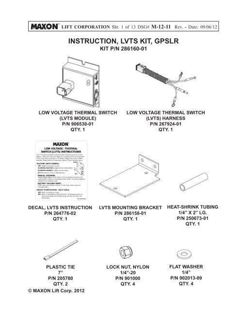
LIFT CORPORATION Sht. 1 of 13 DSG# M-<strong>12</strong>-<strong>11</strong> Rev. - Date: 09/06/<strong>12</strong><strong>INSTRUCTION</strong>, <strong>LVTS</strong> <strong>KIT</strong>, GPSLR<strong>KIT</strong> P/N <strong>286160</strong>-<strong>01</strong>LOW VOLTAGE THERMAL SWITCH(<strong>LVTS</strong> MODULE)P/N 906530-<strong>01</strong>QTY. 1LOW VOLTAGE THERMAL SWITCH(<strong>LVTS</strong>) HARNESSP/N 267924-<strong>01</strong>QTY. 1DECAL, <strong>LVTS</strong> <strong>INSTRUCTION</strong>P/N 264776-02QTY. 1<strong>LVTS</strong> MOUNTING BRACKETP/N 286158-<strong>01</strong>QTY. 1HEAT-SHRINK TUBING1/4” X 2” LG.P/N 250673-<strong>01</strong>QTY. 1PLASTIC TIE7”P/N 205780QTY. 2© MAXON Lift Corp. 20<strong>12</strong>LOCK NUT, NYLON1/4”-20P/N 9<strong>01</strong>000QTY. 4FLAT WASHER1/4”P/N 902<strong>01</strong>3-09QTY. 4
LIFT CORPORATION Sht. 4 of 13 DSG# M-<strong>12</strong>-<strong>11</strong> Rev. - Date: 09/06/<strong>12</strong>3. Remove pump cover to gainaccess to wiring connections(FIG. 4-1).PUMP COVERLATCHES(2 PLACES)REMOVING PUMP COVERFIG. 4-1RHSIDE4. If equipped, remove plugs fromholes (FIG. 4-2).PLUGSREMOVING PLUGSFIG. 4-2RHSIDE© MAXON Lift Corp. 20<strong>12</strong>
LIFT CORPORATION Sht. 5 of 13 DSG# M-<strong>12</strong>-<strong>11</strong> Rev. - Date: 09/06/<strong>12</strong>5. If not equipped with plugged holes,measure and mark two holes onpump mounting plate (FIG. 5-1).Drill two holes in pump mountingplate to mount the <strong>LVTS</strong> bracket(FIG. 5-1).5”6”9/32” DIA. HOLES(2 PLACES)7-1/2”DRILL HOLES IN PUMP BOX(RH SIDE)FIG. 5-1© MAXON Lift Corp. 20<strong>12</strong>
LIFT CORPORATION Sht. 6 of 13 DSG# M-<strong>12</strong>-<strong>11</strong> Rev. - Date: 09/06/<strong>12</strong>6. Attach <strong>LVTS</strong> mounting bracket,(Kit item) to RH pump box plate(FIG. 6-1). Then, Attach <strong>LVTS</strong> module(Kit item) to the <strong>LVTS</strong> mountingbracket (FIG. 6-1).RH PUMPBOX PLATEFLAT WASHER1/4”(2 PLACES)LOCK NUT1/4”-20(2 PLACES)LOCK NUT1/4”-20(2 PLACES) CAP SCREW1/4”-20 X 3/4”, GR8(2 PLACES)FLAT WASHER1/4”(2 PLACES)<strong>LVTS</strong>MODULEPAN HEAD SCREW1/4”-20 X 3/4”(2 PLACES)ATTACH MOUNTING BRACKET AND <strong>LVTS</strong>MODULE TO PUMP BOXFIG. 6-1© MAXON Lift Corp. 20<strong>12</strong>
LIFT CORPORATION Sht. 7 of 13 DSG# M-<strong>12</strong>-<strong>11</strong> Rev. - Date: 09/06/<strong>12</strong>NOTE: MAXON recommends using dielectric greaseon all electrical connections.7. Connect <strong>LVTS</strong> harness(Kit item) to <strong>LVTS</strong> module(FIGS. 7-1 and 7-2).FIG. 7-1CONNECTORS<strong>LVTS</strong> HARNESSCATCH<strong>LVTS</strong> MODULELATCHCONNECTING <strong>LVTS</strong> HARNESSTO <strong>LVTS</strong> MODULEFIG. 7-2© MAXON Lift Corp. 20<strong>12</strong>
LIFT CORPORATION Sht. 8 of 13 DSG# M-<strong>12</strong>-<strong>11</strong> Rev. - Date: 09/06/<strong>12</strong>! CAUTIONRoute electrical wires clear of the pump cover and any sharp edges. Avoidmaking sharp bends in wiring. Connect wiring only as shown in the instructionsthat follow.8. Cut white wire from pump control wiring harness(FIG. 8-1). Then, remove ring terminal and discardunused portion of white wire (FIG. 8-1).CUT WHITEWIREPUMP CONTROLWIRING HARNESSRING TERMINAL(+) COIL POSTDISCARD UNUSEDWHITE WIRECUTTING WHITE WIREFIG. 8-1<strong>LVTS</strong>WHITE WIRE© MAXON Lift Corp. 20<strong>12</strong>
LIFT CORPORATION Sht. 9 of 13 DSG# M-<strong>12</strong>-<strong>11</strong> Rev. - Date: 09/06/<strong>12</strong>9. Crimp pump control harness white wire to malebullet on <strong>LVTS</strong> white wire (FIGS. 9-1, 9-2 and 10-1). Then, apply heat shrink (kit item) as shown inFIGS. 9-1, 9-2 and 10-1.PUMP CONTROLWIRING HARNESSWHITEWIRE<strong>LVTS</strong>WHITE WIREFIG. 9-1WHITEWIREMALEBULLETHEATSHRINK<strong>LVTS</strong>HARNESSPUMP CONTROLHARNESSWHITE WIRECONNECTING WHITE WIREFIG. 9-2© MAXON Lift Corp. 20<strong>12</strong>
LIFT CORPORATION Sht. 10 of 13 DSG# M-<strong>12</strong>-<strong>11</strong> Rev. - Date: 09/06/<strong>12</strong>!CAUTIONTo prevent damage to metal case starter solenoid, hold bottom terminalnut securely when loosening and tightening top terminal nut. Do not overtightenthe terminal nuts. For the 5/16” load terminals, torque nuts 40 lbs.-in.Torque the nuts on #10-32 control terminals 15-20 lbs.-in.10. Connect <strong>LVTS</strong> BLACK, GREEN and RED wires to starter switch as shown inFIG. 10-1.RELAY ASSEMBLY/CONTROLLERWHITE WIRE(MALE BULLET)STARTERSWITCH(+) COILPOST(-) COILPOSTMOTORPUMP CONTROLWIRE HARNESSWHITE WIRE(<strong>LVTS</strong> HARNESS)HEATSHRINKBLUE, YELLOW,GREEN, BLACK & REDWIRE CONNECTIONSNOT SHOWNBATTERYPOWERPOSTRED WIRE<strong>LVTS</strong>MODULEBLACK WIREGREEN WIRECONNECTING <strong>LVTS</strong> HARNESSFIG. 10-1© MAXON Lift Corp. 20<strong>12</strong>
LIFT CORPORATION Sht. <strong>11</strong> of 13 DSG# M-<strong>12</strong>-<strong>11</strong> Rev. - Date: 09/06/<strong>12</strong>! CAUTIONFor cover gasket to seal correctly, each <strong>LVTS</strong> decal must be attached clearof the gasket sealing surface.NOTE: <strong>LVTS</strong> instruction decal must be attached to the inside of pump cover & mustbe readable with cover removed.<strong>11</strong>. Attach <strong>LVTS</strong> instruction decal (FIG. <strong>11</strong>-1)to inside wall of pump cover (FIG. <strong>11</strong>-2).<strong>LVTS</strong> <strong>INSTRUCTION</strong> DECALFIG. <strong>11</strong>-1DECAL ATTACHED INSIDE PUMP COVERFIG. <strong>11</strong>-2© MAXON Lift Corp. 20<strong>12</strong>
LIFT CORPORATION Sht. <strong>12</strong> of 13 DSG# M-<strong>12</strong>-<strong>11</strong> Rev. - Date: 09/06/<strong>12</strong><strong>12</strong>. Connect negative (-) battery cableto negative (-) stud on the battery(FIG. <strong>12</strong>-1). Reinstall and tightennut (FIG. <strong>12</strong>-1).NEGATIVE (-)BATTERY CABLENEGATIVE (-)STUDNUTRECONNECTING BATTERYFIG. <strong>12</strong>-<strong>11</strong>3. Use the <strong>LVTS</strong> instruction decal(FIG. <strong>12</strong>-2) to ensure <strong>LVTS</strong> andLiftgate function correctly.<strong>LVTS</strong> <strong>INSTRUCTION</strong> DECALFIG. <strong>12</strong>-2© MAXON Lift Corp. 20<strong>12</strong>
LIFT CORPORATION Sht. 13 of 13 DSG# M-<strong>12</strong>-<strong>11</strong> Rev. - Date: 09/06/<strong>12</strong>14. When kit installation and <strong>LVTS</strong> checkare completed, reinstall pump cover(FIG. 13-1).REINSTALLING PUMP COVERFIG. 13-1© MAXON Lift Corp. 20<strong>12</strong>