Shure UA845 User Guide English - J&H Licht en Geluid
Shure UA845 User Guide English - J&H Licht en Geluid
Shure UA845 User Guide English - J&H Licht en Geluid
- No tags were found...

You also want an ePaper? Increase the reach of your titles
YUMPU automatically turns print PDFs into web optimized ePapers that Google loves.
Model <strong>UA845</strong> <strong>User</strong> <strong>Guide</strong>ANTENNA DISTRIBUTION SYSTEMUSER'S GUIDE©2006, <strong>Shure</strong> Incorporated27AS8862 (Rev.1)Printed in U.S.A.
POWERING ON/POWERING OFF THE <strong>UA845</strong>Last powered onFirst powered offTo avoid damaging internal compon<strong>en</strong>ts, the <strong>UA845</strong> amplifiershould be the last compon<strong>en</strong>t in your system to be powered on.To avoid damaging internal compon<strong>en</strong>ts, the <strong>UA845</strong> amplifiershould be the first compon<strong>en</strong>t in your system to be powered off.CONNECTING ANTENNA CABLESAccid<strong>en</strong>tally connecting the c<strong>en</strong>ter cable pin (power supply) to the cable housing (ground) may cause internal compon<strong>en</strong>t damage. Usecaution wh<strong>en</strong> installing cables.SAFETY INFORMATION! IMPORTANT SAFETY INSTRUCTIONS !1. READ these instructions.2. KEEP these instructions.3. HEED all warnings.4. FOLLOW all instructions.5. DO NOT use this apparatus near water.6. CLEAN ONLY with dry cloth.7. DO NOT block any v<strong>en</strong>tilation op<strong>en</strong>ings. Install in accordance with the manufacturer'sinstructions.8. DO NOT install near any heat sources such as radiators, heat registers, stoves,or other apparatus (including amplifiers) that produce heat.9. DO NOT defeat the safety purpose of the polarized or grounding-type plug. Apolarized plug has two blades with one wider than the other. A grounding typeplug has two blades and a third grounding prong. The wider blade or the thirdprong are provided for your safety. If the provided plug does not fit into youroutlet, consult an electrician for replacem<strong>en</strong>t of the obsolete outlet.10. PROTECT the power cord from being walked on or pinched, particularly at plugs,conv<strong>en</strong>i<strong>en</strong>ce receptacles, and the point where they exit from the apparatus.11. ONLY USE attachm<strong>en</strong>ts/accessories specified by the manufacturer.12.USE only with a cart, stand, tripod, bracket, or tablespecified by the manufacturer, or sold with theapparatus. Wh<strong>en</strong> a cart is used, use caution wh<strong>en</strong>moving the cart/apparatus combination to avoidinjury from tip-over.13. UNPLUG this apparatus during lightning storms or wh<strong>en</strong> unused for long periods oftime.14. REFER all servicing to qualified service personnel. Servicing is required wh<strong>en</strong> theapparatus has be<strong>en</strong> damaged in any way, such as power-supply cord or plug is damaged,liquid has be<strong>en</strong> spilled or objects have fall<strong>en</strong> into the apparatus, the apparatushas be<strong>en</strong> exposed to rain or moisture, does not operate normally, or has be<strong>en</strong>dropped.15. DO NOT expose the apparatus to dripping and splashing. DO NOT put objects filledwith liquids, such as vases, on the apparatus.This symbol indicates that dangerous voltage constituting arisk of electric shock is pres<strong>en</strong>t within this unit.This symbol indicates that there are important operating andmaint<strong>en</strong>ance instructions in the literature accompanying this unit.TABLE OF CONTENTSSAFETY INFORMATION . . . . . . . . . . . . . . . . . . . . . . . . . . . . . . . . . . . . . . . . . . . . . . . . . . . 3SYSTEM FEATURES . . . . . . . . . . . . . . . . . . . . . . . . . . . . . . . . . . . . . . . . . . . . . . . . . . . . . 4CONTROLS AND CONNECTORS . . . . . . . . . . . . . . . . . . . . . . . . . . . . . . . . . . . . . . . . . . . 5SYSTEM INSTALLATION . . . . . . . . . . . . . . . . . . . . . . . . . . . . . . . . . . . . . . . . . . . . . . . . . . 6CONNECTING RECEIVERS . . . . . . . . . . . . . . . . . . . . . . . . . . . . . . . . . . . . . . . . . . . . . . . . 7SPECIFICATIONS . . . . . . . . . . . . . . . . . . . . . . . . . . . . . . . . . . . . . . . . . . . . . . . . . . . . . . . . 9LICENSING AND WARRANTY INFORMATION . . . . . . . . . . . . . . . . . . . . . . . . . . . . . . . . 103
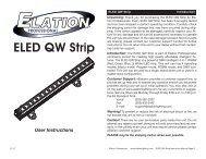
MODEL <strong>UA845</strong> ANTENNA DISTRIBUTION SYSTEMpower<strong>UA845</strong>UHF Ant<strong>en</strong>na Distribution SystemThe <strong>Shure</strong> Model <strong>UA845</strong> is an amplified, UHF Ant<strong>en</strong>na DistributionSystem that expands a wireless microphone system by splittingone pair of ant<strong>en</strong>nas to multiple <strong>Shure</strong> U4 or <strong>Shure</strong> UC4 wirelessreceivers. It also amplifies RF signals to comp<strong>en</strong>sate for insertionloss due to splitting signal power to mulitple output connectors.Each <strong>UA845</strong> allows up to four receivers to use the same ant<strong>en</strong>nas.CASCADE connectors allows connections to a fifth receiver or asecond <strong>UA845</strong>. There are also power connectors for powering<strong>Shure</strong> UHF and UC Wireless systems.Each system contains the following items:• <strong>UA845</strong> Ant<strong>en</strong>na Distribution System• Rack-mounting hardware• Surface-mounting hardware• Front-mounting ant<strong>en</strong>na hardware• 18-in. Power OUTPUT Cord• Power Cord• Ant<strong>en</strong>na cables for receiver connections• DC power cables for receiver connections to DC power connectorson UC receivers.The <strong>Shure</strong> Model <strong>UA845</strong> <strong>en</strong>sures maximum s<strong>en</strong>sitivity and signalprocessing capability, providing the widest radio range possiblefor the largest number of wireless receivers. To get the most fromthis system, follow these guidelines:• Wh<strong>en</strong> using long runs of cable for remote-mounted ant<strong>en</strong>nas,use the UA830 In-Line RF Amplifier and the <strong>Shure</strong> ModelUA825 or UA850 Remote Ant<strong>en</strong>na Ext<strong>en</strong>sion cables (RG-8/Xor equival<strong>en</strong>t), which have low loss at UHF operatingfrequ<strong>en</strong>cies• Locate multiple transmitters more than 3 m [10 ft] fromreceiving ant<strong>en</strong>nasSYSTEM FEATURES• Expandability. The <strong>UA845</strong> UHF Ant<strong>en</strong>na Distribution Systemis designed for large UHF wireless systems. Each unit allowsup to four wireless receivers to use the same two ant<strong>en</strong>nas,and the CASCADE ports allow connection to a fifth receiver ora second <strong>UA845</strong>.• Compatibility. The <strong>UA845</strong> is compatible with all <strong>Shure</strong> wirelessmicrophone receivers operating within a compatible frequ<strong>en</strong>cyrange (see UHF Carrier Frequ<strong>en</strong>cy Ranges in theSpecifications section).• CASCADE Ports. Two 50 Ω, BNC-type ant<strong>en</strong>na CASCADEports allow an additonal <strong>UA845</strong> unit or a fifth wireless receiver.A large wireless system can be run off of a single pair of ant<strong>en</strong>nas.• Power OUTPUT and OUT Connectors. Up to five (5) U4 receiverscan be daisy-chained and powered from a singlesource via the Power OUTPUT connectors. Up to four (4) UC4receivers can be powered from the <strong>UA845</strong> using the 12 VdcOUT connectors.• Low Noise and Intermodulation Distortion. The <strong>UA845</strong>maintains clean signals with minimal distortion.• Insertion Loss Comp<strong>en</strong>sation. Wh<strong>en</strong>ever a signal is split tomultiple output ports, there is a loss in signal str<strong>en</strong>gth. The<strong>UA845</strong> amplifies signals to comp<strong>en</strong>sate, <strong>en</strong>suring a strong signalto the receivers.• Front-Mounted Ant<strong>en</strong>nas. The <strong>UA845</strong> comes with hardwareto front-mount the ant<strong>en</strong>nas, if desired.ENGLISH4
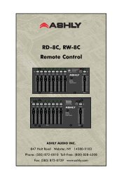
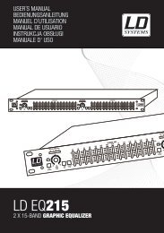
CONTROLS AND CONNECTORSFront Panel<strong>UA845</strong>UHF ANTENNA DISTRIBUTION SYSTEM1 2FRONT PANELFIGURE 1POWER INDICATORPOWER ON/OFFSWITCHBack Panel6 61 2 3 4 5 3 4 5BACK PANELFIGURE 2123AC Power INPUT Connector.AC Power OUTPUT Connector. Each <strong>UA845</strong> has aPower OUTPUT connector for daisy-chaining up to five(5) <strong>Shure</strong> Model U4 UHF Diversity Single or Dual Receiversto a single power source.NOTE: This connector does not work for <strong>Shure</strong> UC4Receivers.ANTENNA IN Ports, Channel A & B. BNC-type connectorsfor ant<strong>en</strong>nas.456RF CASCADE Connectors (Output connector 5),Channel A & B. BNC-type connectors for adding a fifthreceiver, or additional <strong>UA845</strong>'s, permitting more wirelessreceivers to be connected.RF OUTPUT Connectors, Channel A & B. BNC-typeconnectors for up to four wireless receivers.12 Vdc OUT Connectors. These power connectors aredesigned to power up to four (4) <strong>Shure</strong> UC4 Wirelesssystems.5 ENGLISH
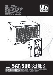
<strong>UA845</strong>UHF Ant<strong>en</strong>na Distribution System<strong>UA845</strong>UHF Ant<strong>en</strong>na Distribution System<strong>UA845</strong>UHF Ant<strong>en</strong>na Distribution SystemSYSTEM INSTALLATIONInstalling Front-Mounted Ant<strong>en</strong>nasThe <strong>UA845</strong> comes equipped for front-mounted ant<strong>en</strong>nas.Front-mounting improves RF performance of the system by movingthe ant<strong>en</strong>nas to the front of the rack. Wh<strong>en</strong> a unit is located in arack, ant<strong>en</strong>nas should be either front- or remote-mounted.1. Insert the bulkhead adapters through the holes in each bracket,and secure them from each side, using the supplied hardware.Mounting the <strong>UA845</strong> in an Equipm<strong>en</strong>t RackNOTE: If front mounting the ant<strong>en</strong>nas, connect them beforemounting the <strong>UA845</strong> in the rack. Once in the rack, it is moredifficult to insert the bulkhead adapters and connect theant<strong>en</strong>na cables.1. Insert the unit into a 19-inch equipm<strong>en</strong>t rack.2. Using the screws supplied, secure the unit to the rack.power<strong>UA845</strong>UHF Ant<strong>en</strong>na Distribution SystemINSERTING BULKHEAD ADAPTERSFIGURE 32. Connect the supplied ant<strong>en</strong>na cables to the receiver ant<strong>en</strong>nainputs and adapters.RACK MOUNTINGFIGURE 63. If the ant<strong>en</strong>nas are remote mounted from the back of the rack,insert the supplied plastic plugs into the holes on the front of thebrackets.Installing Remote Ant<strong>en</strong>nasRemote-mounted ant<strong>en</strong>nas have the advantage of being freefrom the unit and closer to the transmitters. They can be placed anywherewithin the recomm<strong>en</strong>ded cable l<strong>en</strong>gth, creating a much widerradio reception range and further reducing the possibility of signaldropout. Wh<strong>en</strong> remote-mounted ant<strong>en</strong>nas are desirable, pleaseask your <strong>Shure</strong> dealer for information on the UA830 In-Line RF Amplifier.Cables are available in UA825 (7.5 m [25 ft]) and UA850 (15m [50 ft]) versions.CONNECT ANTENNA CABLESFIGURE 43. Install the ant<strong>en</strong>nas onto the bulkhead adapters protrudingthrough the front panel. See 5.<strong>UA845</strong>RECEIVERSpowerpowerpower<strong>UA845</strong>UHF Ant<strong>en</strong>na Distribution SystempowerATTACH ANTENNAS TO THE ADAPTERSFIGURE 5NOTE: For the best results, point the ant<strong>en</strong>nas up and awayfrom each other at 45° angles from vertical. This <strong>en</strong>sures thebest possible reception and greatly reduces the possibility ofsignal dropout. Always perform a walk-through test of thesystem in the performing area before using a wireless system.REMOTE-MOUNTED ANTENNASFIGURE 7ENGLISH6
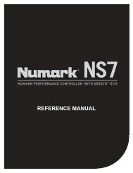
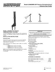
CONNECTING RECEIVERSSingle <strong>UA845</strong> Setup1. Using low-loss, 50 Ω coaxial cables (RG-58 or equival<strong>en</strong>t), connectthe right and left (Channels 1 through 4, A and B) RFOUTPUT ports on the <strong>UA845</strong> to the corresponding left andright ant<strong>en</strong>na inputs on each receiver. Use the CASCADE portsto connect a fifth receiver.2. Using the supplied power cable, connect the <strong>UA845</strong> to a poweroutlet.3. To daisy-chain U4 Receivers together with Power OUTPUTcables, connect the Power OUTPUT connector of the <strong>UA845</strong> tothe Power INPUT connector of one receiver. Connect theremaining receivers similarly. Connect the POWER INPUT ofthe unit to a power supply.NOTE: No more than five (5) <strong>Shure</strong> UHF receivers should bepowered through a daisy-chain from a single <strong>UA845</strong>.4. To power <strong>Shure</strong> UC4 receivers, connect the power input ports ofthe UC4 receivers to the 12 Vdc OUT of the <strong>UA845</strong>. Up to fourUC4 Receivers can be powered.12 VDC POWER CONNECTORANT B INAC PWR OUTPUTAC PWR INPUT<strong>UA845</strong>CASCADE B CASCADE AANT B OUTS12 VDC POWER CONNECTORANT A INANT A OUTSTO POWER SUPPLYTORECEIVERSTORECEIVERSAC PWR OUTPUTAC PWR INPUTANT B INU4 RECEIVERANT A IN12 VDC PWR INPUTU4 RECEIVERANT A INANT B IN<strong>UA845</strong>TO POWER SUPPLYTO RECEIVERSTORECEIVERSU4 RECEIVERTO <strong>UA845</strong> ANT B INTO <strong>UA845</strong>ANT A INMULTIPLE <strong>UA845</strong> SETUPFIGURE 87 ENGLISH
SPECIFICATIONSUHF Carrier Frequ<strong>en</strong>cy Range<strong>UA845</strong>-UA ............................................................782–806 MHz<strong>UA845</strong>-UB ............................................................692–716 MHz<strong>UA845</strong>-MA ............................................................782–810 MHz<strong>UA845</strong>-MB ............................................................800–830 MHz<strong>UA845</strong>-KK.............................................................838–862 MHz<strong>UA845</strong>-MC............................................................774–782 MHz<strong>UA845</strong> US.............................................................500–900 MHz<strong>UA845</strong> UK.............................................................500–900 MHz<strong>UA845</strong> E ...............................................................500–900 MHzDistributed Output Level (Gain)Models <strong>UA845</strong>-UA, UB, MA, MB, KK, MC:3.5 dB typical, 2.0 dB to 5.0 dB from ant<strong>en</strong>na input(Output ports 1–4).0.5 dB typical, –1.0 dB to 2.0 dB from ant<strong>en</strong>na input(Cascade port)Models<strong>UA845</strong> US, UK and E:3 dB typical, 0 dB to 3.5 dB from ant<strong>en</strong>na input(Output ports 1–4)1 dB typical, –1.6 dB to +1.8 dB from ant<strong>en</strong>na input(Cascade port)Output Connector IsolationGreater than 25 dBThird Order Intercept Point (3 OIP)Typical 24 dBmInput/Output AC Line Voltage100 to 240 Vac, 50/60 Hz, unswitchedDC Output Voltage12 Vdc, 4 connectorsMaximun Curr<strong>en</strong>t Supply from DC Outputs1.1 AmpsImpedance50 ΩOperating Temperature Range–7° C (+20° F) to 49° C (+120° F)Overall Dim<strong>en</strong>sions44.5 mm high x 482.6 mm wide x 295.3 mm deep(1 3/4 x 19 5/8 x 11inches)Net Weight3.32 Kg (7 lbs, 5 oz)Input/Output Ant<strong>en</strong>na Connector TypeBNC-typeAC Power Consumption15 W per unit typical. Wh<strong>en</strong> used with 4 UC4's, 55 W max.Certification<strong>UA845</strong>: LISTED by UL and CUL (U.S. and Canada), IC andFCC; IC Certified (Canada). Meets applicable European directivesfor CE marking eligibility. VDE GS-Certified. Meets Requirem<strong>en</strong>tsof EMC Standard and 301 489 Parts 1 and 9. Meetsthe ess<strong>en</strong>tial requirem<strong>en</strong>ts of the European R&TTE Directive99/5/EC and are eligible to carry the CE marking.N108Furnished Accessories2 ft. Coaxial Ant<strong>en</strong>na Cable (RG-58) (12) ....................... UA802Optional Accessories1/2-Wave Ant<strong>en</strong>naUA820A ..............................................................(774–865 MHz)UA820B ..............................................................(690–746 MHz)UA820C..............................................................(662–698 MHz)UA820D..............................................................(554–590 MHz)UA820E ..............................................................(746–784 MHz)25 ft. Coaxial Cable (RG-8/X).......................................... UA82550 ft. Coaxial Cable (RG-8/X).......................................... UA85030.4 m (100 ft.) Ant<strong>en</strong>na Ext<strong>en</strong>sion Cable.................... UA8100In-Line RF AmplifierUA830A ..............................................................(782–810 MHz)UA830UB............................................................(692–716 MHz)UA830C..............................................................(800–830 MHz)UA830D..............................................................(774–782 MHz)UA830KK............................................................(838–862 MHz)UA830WB...........................................................(470–900 MHz)Active Directional Ant<strong>en</strong>naUA870A .............................................................(782–810 MHz)UA870MB ...........................................................(800–830 MHz)UA870MC...........................................................(774–782 MHz)UA870KK............................................................(838–862 MHz)UA870UB............................................................(692–716 MHz)UA870WB...........................................................(470–900 MHz)Replacem<strong>en</strong>t PartsHardware Kit.............................................................. 90XN1371Bulkhead Adapters .......................................................95A8994120 VAC Power Line Cord............................................95B8389230 VAC Power Line Cord............................................95C8247240 VAC Power Line Cord (U.K.) .................................95A8713230 VAC Power Line Cord (AZ)....................................95B9128AC Jumper Power Cord (AZ)........................................95B9129120 VAC, 16-in. Power-Through Cord..........................95B8576230 VAC, 18-in. Power-Through Cord..........................95B867812 Vdc Power Cables ...................................................95B8420THIS RADIO EQUIPMENT IS INTENDED FOR USE IN MUSICAL PROFESSIONAL ENTERTAINMENT AND SIMILARAPPLICATIONS.NOTE: THIS RADIO APPARATUS MAY BE CAPABLE OF OPERATING ON SOME FREQUENCIES NOT AUTHORIZED INYOUR REGION. PLEASE CONTACT YOUR NATIONAL AUTHORITY TO OBTAIN INFORMATION ON AUTHORIZEDFREQUENCIES FOR WIRELESS MICROPHONE PRODUCTS IN YOUR REGION9 ENGLISH
LICENSING AND WARRANTY INFORMATIONWarranty. <strong>Shure</strong> Incorporated (“<strong>Shure</strong>”) hereby warrants that these products will be free from defects in material and workmanship fora period of two years from the date of purchase. At its option, <strong>Shure</strong> will repair or replace the defective product and promptly return it to you,or refund the purchase price. Retain proof of purchase to validate the purchase date and return it with any warranty claim. If you believe thisproduct is defective within the warranty period, carefully repack the unit, insure it, and return it postpaid to:<strong>Shure</strong> IncorporatedAtt<strong>en</strong>tion: Service Departm<strong>en</strong>t5800 W. Touhy Av<strong>en</strong>ueNiles, IL 60714-4608 U.S.A.For service outside the United States, return the product to your authorized <strong>Shure</strong> Distribution C<strong>en</strong>ter.All claims of defects or shortage should be directed to the above address. Please furnish model number, operating frequ<strong>en</strong>cy, and date,place and proof of purchase (such as a copy of your sales receipt) to establish warranty. Your letter should include all pertin<strong>en</strong>t details includingapplicable model or part numbers and a brief description of the problem. Do not mail any units or parts to <strong>Shure</strong> unless requestedto do so by <strong>Shure</strong>'s Service Departm<strong>en</strong>t. Any returned items must have prior authorization. Unauthorized returns are delayed in handling;these delays can be avoided by contacting <strong>Shure</strong> in advance and furnishing the necessary information.<strong>Shure</strong> reserves the right to make design changes and product improvem<strong>en</strong>ts on any previously manufactured products. <strong>Shure</strong> also reservesthe right to ship new and/or improved products which are similar to the form, fit and function of the originally ordered products.Lic<strong>en</strong>sing. Changes or modifications not expressly approved by <strong>Shure</strong> Incorporated could void your authority to operate the equipm<strong>en</strong>t.Lic<strong>en</strong>sing of <strong>Shure</strong> wireless microphone equipm<strong>en</strong>t is the user's responsibility, and lic<strong>en</strong>sability dep<strong>en</strong>ds on the user's classification andapplication, and on the selected frequ<strong>en</strong>cy. <strong>Shure</strong> strongly urges the user to contact the appropriate telecommunications authority concerningproper lic<strong>en</strong>sing, and before choosing and ordering frequ<strong>en</strong>cies other than standard frequ<strong>en</strong>cies.ENGLISH10
SHURE Incorporated http://www.shure.com미국 , 캐나다 , 중남미 , 카리브해 지역5800 W. Touhy Av<strong>en</strong>ue, Niles, IL 60714-4608, U.S.A.전화 : 1-847-600-2000 미국 팩스 : 1-847-600-1212국제 팩스 : 847-600-6446유럽 , 중동 , 아프리카 :<strong>Shure</strong> Europe GmbH, 전화 : 49-7131-72140 팩스 : 49-7131-721414아시아 , 태평양 :<strong>Shure</strong> Asia Limited, 전화 : 852-2893-4290 팩스 : 852-2893-4055SHURE Incorporated http://www.shure.com米 国 、 カナダ、 中 南 米 、 カ リ ブ 海 諸 国 :5800 W. Touhy Av<strong>en</strong>ue, Niles, IL 60714-4608, U.S.A.Tel:847-600-2000 米 国 内 Fax:847-600-1212海 外 からの Fax: 847-600-6446ヨ ーロ ッ パ、 中 東 、 ア フ リ カ :<strong>Shure</strong> Europe GmbH, Tel:49-7131-72140 Fax: 49-7131-721414アジア 太 平 洋 :<strong>Shure</strong> Asia Limited, Tel:852-2893-4290 Fax: 852-2893-4055SHURE Incorporated http://www.shure.com美 国 、 加 拿 大 、 拉 丁 美 洲 、 加 勒 比 海 地 区 :5800 W. Touhy Av<strong>en</strong>ue, Niles, IL 60714-4608, U.S.A.电 话 :847-600-2000 美 国 传 真 :847-600-1212国 际 传 真 : 847-600-6446欧 洲 、 中 东 、 非 洲 :<strong>Shure</strong> Europe GmbH, 电 话 :49-7131-72140 传 真 : 49-7131-721414亚 太 地 区 :<strong>Shure</strong> Asia Limited, 电 话 :852-2893-4290 传 真 : 852-2893-4055SHURE Incorporated http://www.shure.comUnited States, Canada, Latin America, Caribbean:5800 W. Touhy Av<strong>en</strong>ue, Niles, IL 60714-4608, U.S.A.Phone: 847-600-2000 U.S. Fax: 847-600-1212Intl Fax: 847-600-6446Europe, Middle East, Africa:<strong>Shure</strong> Europe GmbH, Phone: 49-7131-72140 Fax: 49-7131-721414Asia, Pacific:<strong>Shure</strong> Asia Limited, Phone: 852-2893-4290 Fax: 852-2893-4055