Wood Design for Architects: AIA Statement AIA ... - WoodWorks
Wood Design for Architects: AIA Statement AIA ... - WoodWorks
Wood Design for Architects: AIA Statement AIA ... - WoodWorks
- No tags were found...

Create successful ePaper yourself
Turn your PDF publications into a flip-book with our unique Google optimized e-Paper software.
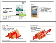
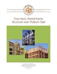
<strong>Wood</strong> <strong>Design</strong> <strong>for</strong> <strong>Architects</strong>:Engineering <strong>for</strong> the Non-engineer<strong>AIA</strong> <strong>Statement</strong>“The <strong>Wood</strong> Products Council” is a Registered Provider with TheAmerican Institute of <strong>Architects</strong> Continuing Education Systems(<strong>AIA</strong>/CES). Credit(s) earned on completion of this program will bereported to <strong>AIA</strong>/CES <strong>for</strong> <strong>AIA</strong> members. Certificates of Completion <strong>for</strong>both <strong>AIA</strong> members and non-<strong>AIA</strong> members are available upon request.This program is registered with <strong>AIA</strong>/CES <strong>for</strong> continuing gprofessionaleducation. As such, it does not include content that may be deemedor construed to be an approval or endorsement by the <strong>AIA</strong> of anymaterial of construction or any method or manner of handling, using,distributing, or dealing in any material or product.Karyn A. Beebe, P.E. , LEED APkaryn.beebe@apawood.org (858) 560-1298 www.apawood.orgQuestions related to specific materials, methods, and services will beaddressed at the conclusion of this presentation.Copyright MaterialsThis presentation is protected by US andInternational Copyright laws. Reproduction,distribution, display and use of the presentationwithout written permission of the speaker isprohibited.© The <strong>Wood</strong> Products Council 2012Learning ObjectivesAt the end of this program, participants will be able to:1. Define the design criteria such as lateral loads in the region, understand howthey impact buildings, and consequently be better prepared to design <strong>for</strong>them.2. Identify the latest changes to the International Codes with respect toengineered wood provisions3. Through h working design examples, apply their new knowledge to buildingdesign.4. Utilize design resources (APA literature and a list of websites andg (publications) addressing the challenges facing today’s wood building designer
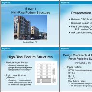
Presentation Agenda<strong>Wood</strong> as a Structural Material• <strong>Wood</strong> as a structural t material• <strong>Design</strong> Criteria• Building Elements• The Unified Structure• <strong>Design</strong> Examples<strong>Wood</strong> has a strength direction<strong>Wood</strong> as a structural materialLoad parallelto grainLoad perpendicularto grainCompression• Parallel – columns, posts, truss chords• Perpendicular – de<strong>for</strong>mation of memberTension• Parallel – Highest strength – beams, panels• Perpendicular – Weakest capacity - connectionsStrongerWeaker
Mechanical Properties of <strong>Wood</strong>Maximum DeflectionLoad, w:Deflection,∆:xLLimited to reduce floor bounce and prevent cracking offinish materials such as drywall and tile(CBC Table 1604.3)ConstructionRoof membersw/drywall clg.Live loaddeflectionTotal loaddeflectionL/240 L/180∆ max =5w*L 4 /(384*E*I)LFloor L/360 L/240membersI – joists* L/480*Per APA <strong>for</strong>m E30, pg 26Mechanical Properties of <strong>Wood</strong>Mechanical Properties of <strong>Wood</strong>Shear stress• Critical at connections, reactions, point loads• Typically not failure mode in flexural members• May control in short spans with heavy loading,cantilever, or continuous spans• Avoid stress concentrations at notches or changes incross section• Calculate maximum shear <strong>for</strong>ce• Allowable Shear Stress = Fv >= 1.5V/A• V = maximum shear• A = Cross Sectional Area• Typical units <strong>for</strong> Shear are pounds (lbs)Load, w:Shear, V:xV=w(L/2-x)LV max =wL/2
Tension Perpendicular to GrainLoad Path Continuity<strong>Wood</strong> splits from:• notches• hanging loads• restraint by connector• Spread out loads from fastenersConsider alternative(large single fastener)Best(multiple small fasteners)Load Path ContinuityNotchingTension perpendicular to grain
Connecting <strong>Wood</strong>Do Not Mix I-joists withDimension i Lumber<strong>Wood</strong>, like other materials, moves in varyingenvironmentsDispersal of Strength ReducingCharacteristics<strong>Wood</strong> as a Structural Material• I-Joist vs. Lumber• Both at 16" o.c.•36% less wood fiber• I-Joist at 19.2" o.c &Lumber at 16" o.c.•46% less wood fiberVS.I-JoistLumber
<strong>Design</strong> Criteria: LoadsVertical Load• Dead Loads (permanent)– structure, partitions, finishes• Live Loads– people, furniture, snow• Wind and Seismic• Impact loads(The effect of loads are lessened with shorter duration)Loads(2010 CBC Chapter 16 & CRC Section R301)Dead Loads (Section 1606)• Weight of permanent loads: construction materials, fixedequipment• Increases from joists to beamsDeadLoads?Live Loads (Table 1607.1)• Live Load Reduction (1607.9)• Reduction in Roof Live Loads (1607.11.2)• Based on supported area, slope roof• Decreases from joists to beams
Loads(2010 CBC Chapter 16 & CRC Section R301.2)Lateral LoadClimatic Loads• Snow (Section 1608)• Rain (Section 1611)Lateral Loads• Wind (Section 1609)• Seismic (Section 1613)Lateral a Loads: National a IssueLoads(2010 CBC Chapter 16 & CRC Section R301)Wind HazardEarthquake HazardLoad Combinations (Section 1605)• 21 EquationsM t h k ll bi ti f i l di• Must check all combinations <strong>for</strong> maximum loading• Examples:• D + L + (L r or S or R)• D + L + ωW• 0.9D + E/1.4
Adjustment FactorsCapacity +/- based on:• Duration of Load• Moisture• Temperature• Chemical Treatments(Found in the National <strong>Design</strong> Specification <strong>for</strong> <strong>Wood</strong>Construction (NDS) published by the American Forest &Paper Association)Load Duration Factor<strong>Wood</strong> capacity greater <strong>for</strong> short time loadingLOAD DURATIONLoad DurationTypical LoadsFactor - CDPermanent 0.9 Dead LoadTen years 1.0 Floor live loadTwo months 1.15 Snow loadSeven days 1.25 Construction loadTen minutes 16 1.6 Wind/EarthquakeImpact 2.0 VehiclesThese factors are applied to member capacity<strong>Design</strong> ConsiderationsEnd restraint conditions:• Simple span has 2 supports• Continuous has 3 or more supports• Cantilevered has 1 support• Supports may be beams, columns, walls…<strong>Design</strong> ConsiderationsLoading Conditions:• Uni<strong>for</strong>m: Dead load, Live loads, pounds per lineal feet (plf)xLSimpleContinuous• Point: Interior Columns, walls, pounds (lbs)CantileveredxL
Building ElementsWhy Engineer?When a building, or portion, doesn’t meet conventionalrequirements it must be engineered(CBC 2308.4, CRC R301.1.3)Gravity <strong>Design</strong>• Horizontal members• Panels• Joists• Beams•Vertical members• Studs• Columns<strong>Wood</strong> Structural PanelsBuilding Elements: PanelsFaceCoreCenterCoreBack
Building Elements: PanelsBuilding Elements: PanelsOSB layers are engineered <strong>for</strong>strength.Roof Span• Deflection = L/240• Live load = 30 psf• Dead load=10psfFloor Span• Deflection = L/360• Live load= 100 psf• Dead load = 10 psfBuilding Elements: PanelsBuilding Elements: Panels• Rated Sheathing• Floor, wall or roof• Plywood or OSBA PARATED SHEATHING32/16SIZED FOR SPACINGEXPOSURE 1THICKNESS 0.451 IN.000PS 2-10 SHEATHINGPRP-108 HUD-UM-4015/32 CATEGORYRoofCovering• Rated Sheathing• Floor, wall or roof• Plywood or OSBA PARATED SHEATHING32/16SIZED FOR SPACINGEXPOSURE 1THICKNESS 0.451 IN.000PS 2-10 SHEATHINGPRP-108 HUD-UM-40PRP-108 HUD-UM-4015/32 CATEGORY
Building Elements: Panels• Sturd-I-Floor• Combined subfloor & underlayment• Resistant to concentrated & impact loads• Plywood or OSBA PARATED STURD-I-FLOOR20 ocSIZED FOR SPACINGT & G NET WIDTH 47-1/2EXPOSURE 1THICKNESS 0.578 IN.000PS 2-10PRP-10819/32 CATEGORYSINGLE FLOORHUD-UM-40Carpet& padAPA Form E30 Table 30Span Rating ConditionsAPA Form E30 Table 33Strength th axisperpendicular tosupportsContinuous across 2 or morespans
Building Elements: JoistsBuilding Elements: Joists• I-joist• Used <strong>for</strong> floor & roof framing• Long lengths availableUni<strong>for</strong>m LoadFlange(LVL or lumber)CompressionTensionWeb(OSB)LCForces are Max. atLCBuilding Elements: JoistsUni<strong>for</strong>m LoadShear ForceC BB CRule of Thumb: Hole size inverselyproportional to shear <strong>for</strong>ce
Building Elements: Rim BoardBuilding Elements: Beams• Laminated Veneer Lumber (LVL)• Veneers bonded together• Beams, headers, rafters& scaffold plankingConstructabilityField Notching and Drilling of LVL(Form G535)Horizontal Hole DrillingAll grain parallelto length
Vertical HolesStrength reduction= 1.5 x Hole diameter/beam width(Forms S560 and G535)Example:• 6” Beam width• 1” diameter vertical holeReduction = 1 x 1.5/6Reduction = 025 0.25Beam is 75% of original strengthSide-loaded Multi-ply BeamsConnection of plies is specified in the NDS andindividual LVL manufacturer literaturePre-engineered engineered ConnectorsGlulamJoist and beam hangers• Top and face mount• Product specific• Use correct nail• Fill all holes• Ensure properpfastener penetrationGlulam
Engineered Lay-upsTOP StampCompression zoneInner zoneTension zoneCritical Tension ZoneBuilding Elements: BeamsStock Beams – Camber is not an issueCamber in stock beams is usually zero or based on a 3500’ or5000’ radius where a 20’ beam has a curvature of 1/8” or lessConstructabilityField Notching and Drilling of Glulam(Form S560)Horizontal Hole Drilling3500’ radiusZero camber
Building Elements: BeamsBuilding Elements: Beams• Preservativetreatment• Naturallydurable woodspecies• Alaskan YellowCedar• Port Or<strong>for</strong>dCedarExposed ConditionsTreated Beams and Columns <strong>for</strong> DecksLVL Hybrid Glulam with LVLOuter Laminations• Full length with nofinger joints required• LVL has greatertensile strengthcompared to lumber• 30F-2.1E stress levelachieved• Direct substitute t <strong>for</strong>many SCL productsLVL LaminationsBuilding Elements: BeamsArchitectural Appearance+ Full Framing Width+ IJC Depths• Maximize versatility –exposed or not• Ease of construction –no shimming requiredStud CapacityBuckling capacity usually controlsBuckling controlled by:• Stud lengthBuckled shape• Stud size (2x4 vs. 2x6)• Stud grade (No.1, No. 2, Stud)• Bracing in weak direction (blocking,drywall)Strong directionWeak direction
Stud BendingBuilt-up up Lumber ColumnsLateral <strong>for</strong>ce onstuds furtherreduces thebuckling capacity.This controls thedesign of exteriorstuds subjected tolateral wind orseismic <strong>for</strong>ces.Buckled shapeMulti-ply columns• Guidance provided in NDS <strong>for</strong>:• Nailed or bolted laminated columns• Nailed K f = 0.60• Bolted K f = 0.75Built-up up Lumber ColumnsBuilding ElementsNail spacing dictated by NDS <strong>for</strong> reduced KfLateral <strong>Design</strong>• Horizontal members• Diaphragms•Vertical members• Shear Walls
Lateral Load PathGravity Load PathLateral Load Path<strong>Design</strong>ing <strong>Wood</strong> Structures to ResistLateral LoadsConventional Light Frame Construction• Prescriptive, uses bracing• Limited as defined by provisionsEngineered Lateral Force Resisting System• Uses shear walls, diaphragms, collectors, etc.
Blocked DiaphragmUnblocked DiaphragmEngineered Shear WallsSpecificstud species<strong>Wood</strong>structuralpanels ofspecific gradeand thicknessHeight to width ratio(SDPWS Table 4.3.4)•For F shear walls andper<strong>for</strong>ated shear walls• h:w must not exceed 2:1or 3.5:1 ratioHold-downanchorsSpecific nailsize andspacingrequirementsBase shear anchor bolts
Max. Shear WallAspect Ratios (2305.3.4)Aspect ratio = height-to-width ht t idth ratio• Height = bottom of bottom plate to top of top plate• Width = sheathed width of wall<strong>Design</strong>1997UBC2000IBC2003-2006 IBCWind 3.5:1 3.5:1 3.5:1Zone 4 2:1 -- --SeismicZone 0-3 3.5:1 -- --SDC D-F -- 2:1 2:1 aSDC A-C -- 3.5:1 2:1 aa. May be reduced to 3.5:1 if allowable shear is reduced by 2w/hShear Wall <strong>Design</strong>(SDPWS 4.3)Segmented Force Transfer Per<strong>for</strong>ated1. Aspect Ratio <strong>for</strong>seismic 2:12. Aspect ratio up to3.5:1, if allowableshear is reducedby 2w/h1. Code does notprovide guidance<strong>for</strong> this method2. Differentapproaches usingrational analysiscould be used1. Code providesspecificrequirements2. The capacity isdetermined basedon empiricalequations andtablesHold-Down PlacementTraditionalHold-Down PlacementPer<strong>for</strong>ated
The Unified StructureLateral Loads(Wind)F = PAEf<strong>for</strong>t is devoteddto determining:P – wind pressureLateral Loads(Seismic)General Modes of FailureF = maEf<strong>for</strong>t is devoteddto determining:a – accelerationUpliftBase ShearRackingOverturning
Breached Building Envelope -F-2 TornadoEasy Upgrade!Reference: APA Report – Midwest Tornados 2003Bottom Plate to Foundation
Lateral Force Resisting SystemsHold-down down hardwareLateral connection strengthdepends on:The Unified Structure• Crushing g( (bearing) strength ofwood• Size of wood pieces• Fastener size and strength• Plus appropriate end useadjustment factors (i.e. Wetservice, edge distance, end grain,etc.)The Unified StructureConsistency CountsWithdrawal ConnectionStrength Depends On:• Depth of penetration• <strong>Wood</strong> density• Fastener size and type• Plus appropriate end useadjustment factors i.e. wetservice, edge distance, endgrain, etc.• Nail sizes• Are you using the right nail?• Specify pennyweight, type,diameter and length• Ex: 8d common = 0.131” x 2-1/2”Type8d Nail SizesLength(in.)Wire Dia.(in.)Finish 2-1/2" 0.099Box & casing 2-1/2" 0113 0.113Siding 2-3/8" 0.106Cooler 2-3/8" 0.113Common 2-1/2" 0.131Ring- or0.120 or2-1/2"screw-shank 0.131
Consistency CountsConsistency Counts• Overdriven fastenersOverdriven FastenersOverdrivenNot OverdrivenOverdrivenFastenersOverdrivenDistanceAction< 20% 1/8"Add 1 <strong>for</strong> everytwo overdrivenAPA Publication TT-012Consistency CountsPre-engineered engineered ConnectorsOverdriven FastenersJoist and beam hangersOverdrivenFastenersAnyOverdrivenDistanceDue toThicknessSwellingActionNone• Top and face mount• Product specific• Use correct nail• Fill all holes• Ensure proper fastenerpenetrationAPA Publication TT-012
Consistency CountsInconsistent Spacing & SpanVariable Spacing …Be Careful !Inconsistent feel &per<strong>for</strong>manceConsistency CountsConsistent Spacing & SpanFloor Sheathing ExampleAnswer:• From Table 12, APA <strong>for</strong>m E30 (pg 33):• For 16” oc spacing= 7/16” 32/16 wood structural panel (WSP)• For 24” oc spacing = 23/32” or ¾” 48/24 WSPGiven:• Span = 16” and 24”• Live load = 40 psf• Dead load = 10 psf<strong>Design</strong> reference: APA <strong>for</strong>m E30
APA Form E30 Table 12Joist ExampleAnswer:• From Table 8, APA <strong>for</strong>m E30 (pg 26):• For 16” oc spacing= 9-1/2” PRI-20• For 24” oc spacing = 9-1/2” PRI-60 or 11-7/8” PRI-20Given:•Spacing = 16” and 24”• Live load = 40 psf• Dead load = 10 psf• Simple Span = 15’<strong>Design</strong> reference: APA <strong>for</strong>m E30APA Form E30 Table 8Beam ExampleAnswer:• From Table 3A, APA <strong>for</strong>m EWS X440B (pg 18):• 3-1/8 x 16-1/2• 3-1/2 x 15• 5-1/8 x 12• Or 5-1/2 x12Given:• Span = 16’-3”• Span roof trusses = 24’• Live load = 40 psf• Dead load = 10 psf<strong>Design</strong> reference: APA <strong>for</strong>m EWSX440B
Beam SizingGiven:Span = 22'Floor live load = 40 psfFloor dead load = 15 psfTributary Width = 18’Find:Beam size <strong>for</strong> l/360deflectionAnswer:From Glulam Floor Beam, APA <strong>for</strong>m C415• For 24F-1.8E beams, see Table 1a (pg 3):5-1/8 x 22-1/2, 5-1/2 x 22-1/2, or 6-3/4 x 21• For IJC 24F-1.8E beams, see Table 2a (pg 5):3-1/2x24, 5-1/2 x 20 or 7 x 18•For 30F-1.8E beams, see Table 3a (pg 8):3-1/2x22, 5-1/2 x 18 or 7 x 18
Beam SizingStructural calculations:1. Define design criteria2. Check maximum bending3. Check Shear4. Check deflection1. Span = 22‘ Floor live load = 40 psfFloor dead load = 15 psfTributary Width = 18’Max. Deflection = l/360Uni<strong>for</strong>m load = W = (D + L)*Tributary Width= 18’*(40 + 15)psf = 990plfSelect 6-3/4 x 21 beam to begin designAPA Form Y117 Table 5Structural calculations:2. Check maximum bendingBeam SizingM max = wl 2 /8 = 990*(22) 2 /8= 59,895 lb-ftFrom APA Form Y117 (pg 12),Moment Capacity = M = 99,225 lb-ftSince M max < M, OK
Structural calculations:3. Check maximum shearBeam SizingV max = wl/2 = 990*(22)/2 = 10,890 lbFrom APAForm Y117 (pg 12),Shear Capacity = V = 25,043 lbBeam SizingStructural calculations:4. Check maximum deflection∆ max = 5wl 4 /(384EI)= 5*990plf*(22’) 4 /(384*9377x10 6 lb-in 2 )*(12”/1’) 3= 0.56”From APA Form Y117(pg 12), EI = 9377x10 6 lb-in 2∆ = l/360 = 22’/360*(12”/1’) = 0.73”Since ∆ max < ∆, OKSince V max
APA Form C415 Table 5ATo <strong>Wood</strong>For 24F-1.8E Glulams:• See Table 4a, APA <strong>for</strong>m EWS C415 (pg 11):3-1/2x15, 5-1/2x13-1/2, or 7x10⁻¹/21/2For 30F-2.1E Glulams:• See Table 5a, APA <strong>for</strong>m EWS C415 (pg 13):3-1/2x14, 5-1/8x11-7/8, or 7x9-1/2Given:ShearWalls:Windv Wind v. Seismic•7/16” OSB•8d commonV5’-4”•3”/ 6” edge/field 8’nail spacing•Gypsum onopposite faceHvHShearWalls:Windv Wind v. Seismic•Wind d Capacity:• V=(450 plf x 1.4+100 plf) x 5.33’ = 3891 lbLength of wallFrom tableFor windS i i C it•Seismic Capacity:• V=450 plf x 5.33’ = 2399 lbFor gypsum from table
Shear Wall <strong>Design</strong> Examples Segmented Shear WallApproach Force Transfer AroundOpening Approach Per<strong>for</strong>ated Shear WallApproachV<strong>Design</strong> Example26’-0”3’-6” 3’-0” 4’-0” 6’-0” 4’-0” 2’-0” 3’-6”6’-8”2’-8” 2’-8”8’-0”V = 3,750 lbsSegmented ApproachSegmented ApproachV3’-6” 3’-0”4’-0” 6’-0” 4’-0” 2’-0” 3’-6”V3’-6” 3’-0”4’-0” 6’-0” 4’-0” 2’-0” 3’-6”6’-8”2’-8” 2’-8”8’-0”6’-8”2’-8” 2’-8”8’-0”Do not consider contribution ofwall below and above openingsH v H H v H H v H H v HCode LimitationV = 3,750 lbsHeight/width Ratio = 8:3.52w/h = (2)(3.5)/8 = 0.875
Segmented ApproachSegmented Approach1. Unit ShearV = V/L = 3,750/15 = 250 lbs/ft2. Allowable Shear 3’-6” wallsv allowable = 380 (0.875)=332 lbs/ft > 250 lbs/ft3. Allowable Shear 4’ walls (2:1 h:w)v allowable = 260lb/ft > 250 lbs/ft4. Hold-down <strong>for</strong>cesH = vh = 250 x 8 = 2,000 lbsNote: For simplicity Dead Load contributionand various footnote adjustments are omitted15/32” Rated Sheathing 8d @ 4”o.c. at 3.5’ walls15/32” Rated Sheathing 8d @ 6”o.c. @ 4’ walls8 – hold downs @ 2000+ lb capacityV15/32”RatedSheathing8d @4”o.c.3’-6” 3’-0” 4’-0” 6’-0” 4’-0” 2’-0”3’-6”6’-8”V = 3,750 lbsv = 250 lbs/ftH = 2,000 lbs2’-8” 2’-8”H v H H v H H v H H v H8 – hold downs @2000+ lb capacity8’-0”15/32” RatedSheathing 8d @ 6”o.c. Segmented Shear WallApproach Force Transfer Around Opening Approach Per<strong>for</strong>ated Shear Wall ApproachPer<strong>for</strong>ated Shear Wall ApproachV26’-0”3’-6” 3’-0” 4’-0” 6’-0” 4’-0” 2’-0” 3’-6”6’-8”2’-8” 2’-8”8’-0”Hv, tv, tv, t v, tHV = 3,750 lbsHeight/width Ratio = 8:3.52w/h = (2)(3.5)/8 = 0.875
Per<strong>for</strong>ated Shear Wall ApproachPer<strong>for</strong>ated Shear Wall Approach1 Unit shear in the wallv = 3,750/15 = 250 lb/ft• SDPWSTable4335ShearResistanceAdjustmentFactor 4.3.3.5 Shear Factor, C O2 Percent of Full-Height Sheathed15/26 = 0.57 (57%)3 Maximum opening height2H/3 = 6’-8”57% 0.61Per<strong>for</strong>ated Shear Wall ApproachPer<strong>for</strong>ated Shear Wall Approach4 Co – Shear Resistance Adjustment t FactorCo = 0.612 say 0.615 Adjusted Shear Resistancev allowable = 490 x 0.875 x 0.61 = 262 lbs/ft > 250 lbs/ft6. Uplift at Per<strong>for</strong>ated Shear Wall ends (hold downs)H = (250/0.61) x 8 = 3,280 lbs7. In-plane Shear AnchorageH = 250/0.61 = 410plf15/32” RatedSheathing8d @ 3”o.c.8. Uplift anchorage between shear wall endst = 250/0.61 = 410 plf (at full segments only)9. Deflection is determined based on the deflection ofany segment of the wall divided by C o
Segmented ApproachForce TransferPer<strong>for</strong>ated15/32” Rated sheathing 8d @4”o.c. (3’-6” walls),@ 6” o.c. (4’ walls)8 – hold downs @2000+ lb capacity15/32” Rated Sheathing8d @ 4”o.c.2 – hold downs @1,550 lb capacity2 Straps – 1,250 lb15/32” Rated Sheathing8d @ 3”o.c.2 – hold downs @3280 lb capacityQuestions/ Comments?This concludes The AmericanInstitute of <strong>Architects</strong> ContinuingEducation Systems CourseHv, tv, tv, t v, tHextensive plateanchorageKaryn A. Beebe, P.E. , LEED APkaryn.beebe@apawood.org (858) 560-1298 www.apawood.org<strong>Wood</strong> Products Council 866.966.3448 info@woodworks.org