Digital Receiver Handbook: Basics of Software Radio
Digital Receiver Handbook: Basics of Software Radio
Digital Receiver Handbook: Basics of Software Radio

You also want an ePaper? Increase the reach of your titles
YUMPU automatically turns print PDFs into web optimized ePapers that Google loves.
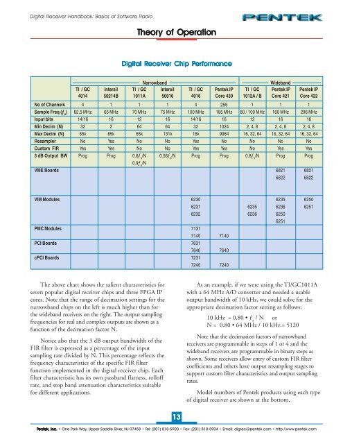
<strong>Digital</strong> <strong>Receiver</strong> <strong>Handbook</strong>: <strong>Basics</strong> <strong>of</strong> S<strong>of</strong>tware <strong>Radio</strong>Theory <strong>of</strong> Operation<strong>Digital</strong> <strong>Receiver</strong> Chip PererformanceNarrowbandWidebandTI / GC Intersil TI / GC Intersil TI / GC Pentek IP TI / GC Pentek IP Pentek IP4014 50214B 1011A 50016 4016 Core 430 1012A / B Core 421 Core 422No <strong>of</strong> Channels 4 1 1 1 4 256 1 1 1Sample Freq (ƒ s) 62.5 MHz 65 MHz 70 MHz 75 MHz 100 MHz 185 MHz 80 / 100 MHz 160 MHz 296 MHzInput bits 14/16 16 12 16 14/16 16 12 16 16Min Decim (N) 32 2 64 64 32 1024 2, 4, 8 2, 4, 8 2, 4, 8Max Decim (N) 65k 65k 65k 131k 16k 9984 16, 32, 64 16, 32, 64 16, 32, 64Resampler No Yes No No Yes No No No NoCustom FIR Yes Yes No No Yes Yes No Yes Yes3 dB Output BW Prog Prog 0.8ƒ s/N 0.56ƒ s/N Prog Prog 0.8ƒ s/N Prog Prog0.9ƒ s/NVME Boards 6821 68216822 6822VIM Modules 6230 6235 62506231 6235 6236 62516232 6236 62506251PMC Modules 71317140 7140PCI Boards 76317640 7640cPCI Boards 72317240 7240The above chart shows the salient characteristics forseven popular digital receiver chips and three FPGA IPcores. Note that the range <strong>of</strong> decimation settings for thenarrowband chips on the left is much higher than forthe wideband receivers on the right. The output samplingfrequencies for real and complex outputs are shown as afunction <strong>of</strong> the decimation factor N.Notice also that the 3 dB output bandwidth <strong>of</strong> theFIR filter is expressed as a percentage <strong>of</strong> the inputsampling rate divided by N. This percentage reflects thefrequency characteristics <strong>of</strong> the specific FIR filterfunction implemented in the digital receiver chip. Eachfilter characteristic has its own passband flatness, roll<strong>of</strong>frate, and stop band attenuation characteristics suitablefor different applications.As an example, if we were using the TI/GC1011Awith a 64 MHz A/D converter and needed a usableoutput bandwidth <strong>of</strong> 10 kHz, we could solve for theappropriate decimation factor setting as follows:10 kHz = 0.80 • ƒ s/ N orN = 0.80 • 64 MHz / 10 kHz = 5120Note that the decimation factors <strong>of</strong> narrowbandreceivers are programmable in steps <strong>of</strong> 1 or 4 and thewideband receivers are programmable in binary steps asshown. Some receivers allow entry <strong>of</strong> custom FIR filtercoefficients and others have output resampling stages tosupport custom filter characteristics and output samplingrates.Model numbers <strong>of</strong> Pentek products using each type<strong>of</strong> digital receiver are shown at the bottom.13Pentek, Inc. • One Park Way, Upper Saddle River, NJ 07458 • Tel: (201) 818-5900 • Fax: (201) 818-5904 • Email: digrec@pentek.com • http://www.pentek.com