Digital Receiver Handbook: Basics of Software Radio
Digital Receiver Handbook: Basics of Software Radio
Digital Receiver Handbook: Basics of Software Radio

Create successful ePaper yourself
Turn your PDF publications into a flip-book with our unique Google optimized e-Paper software.
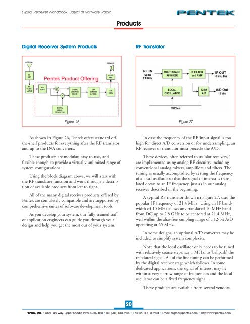
<strong>Digital</strong> <strong>Receiver</strong> <strong>Handbook</strong>: <strong>Basics</strong> <strong>of</strong> S<strong>of</strong>tware <strong>Radio</strong>Products<strong>Digital</strong> <strong>Receiver</strong> System ProductsRF TranslatorFigure 26Figure 27As shown in Figure 26, Pentek <strong>of</strong>fers standard <strong>of</strong>fthe-shelfproducts for everything after the RF translatorand up to the D/A converters.These products are modular, easy-to-use, andflexible enough to provide a virtually unlimited range <strong>of</strong>system configurations.Using the block diagram above, we will start withthe RF translator function and work through a description<strong>of</strong> available products from left to right.All <strong>of</strong> the many digital receiver products <strong>of</strong>fered byPentek are completely compatible and are supported bycomprehensive suites <strong>of</strong> s<strong>of</strong>tware development tools.As you develop your system, our fully-trained staff<strong>of</strong> application engineers can guide you through yourdesign and help you get the most out <strong>of</strong> your system.In case the frequency <strong>of</strong> the RF input signal is toohigh for direct A/D conversion or for undersampling, anRF receiver or translator must precede the A/D.These devices, <strong>of</strong>ten referred to as “slot receivers,”are implemented using analog RF circuitry includingconventional analog mixers, amplifiers and filters. Thetuning is usually accomplished by setting the frequency<strong>of</strong> a local oscillator so that the signal <strong>of</strong> interest is translateddown to an IF frequency, just as in our analogreceiver described in the beginning.A typical RF translator shown in Figure 27, uses thepopular IF frequency <strong>of</strong> 21.4 MHz. Using an IF bandwidth<strong>of</strong> 10 MHz allows any translated 10 MHz bandfrom DC up to 2.8 GHz to be centered at 21.4 MHz,well within the alias-free sampling range <strong>of</strong> a 12-bit A/Doperating at 65 MHz.In some designs, an optional A/D converter may beincluded to simplify system complexity.Note that the local oscillator only needs to be tunedwith relatively coarse steps, say 1 MHz, to ‘ballpark’ thetranslated signal. All <strong>of</strong> the fine tuning can be performedby the digital receiver stage which follows. In somededicated applications, the signal <strong>of</strong> interest may liewithin a very narrow range <strong>of</strong> frequencies and the localoscillator can be a fixed frequency signal.These products are available from several vendors.20Pentek, Inc. • One Park Way, Upper Saddle River, NJ 07458 • Tel: (201) 818-5900 • Fax: (201) 818-5904 • Email: digrec@pentek.com • http://www.pentek.com