Digital Receiver Handbook: Basics of Software Radio
Digital Receiver Handbook: Basics of Software Radio
Digital Receiver Handbook: Basics of Software Radio

Create successful ePaper yourself
Turn your PDF publications into a flip-book with our unique Google optimized e-Paper software.
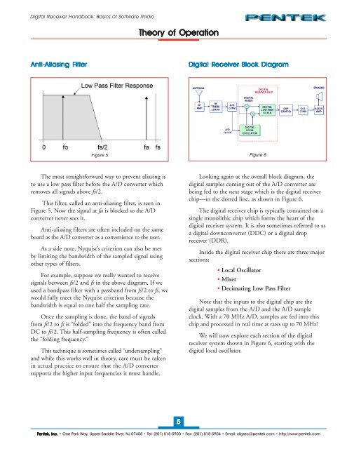
<strong>Digital</strong> <strong>Receiver</strong> <strong>Handbook</strong>: <strong>Basics</strong> <strong>of</strong> S<strong>of</strong>tware <strong>Radio</strong>Theory <strong>of</strong> OperationAnti-Aliasing Aliasing Filter<strong>Digital</strong> <strong>Receiver</strong> Block DiagramFigure 5 Figure 6The most straightforward way to prevent aliasing isto use a low pass filter before the A/D converter whichremoves all signals above fs/2.This filter, called an anti-aliasing filter, is seen inFigure 5. Now the signal at fa is blocked so the A/Dconverter never sees it.Anti-aliasing filters are <strong>of</strong>ten included on the sameboard as the A/D converter as a convenience to the user.As a side note, Nyquist’s criterion can also be metby limiting the bandwidth <strong>of</strong> the sampled signal usingother types <strong>of</strong> filters.For example, suppose we really wanted to receivesignals between fs/2 and fs in the above diagram. If weused a bandpass filter with a passband from fs/2 to fs, wewould fully meet the Nyquist criterion because thebandwidth is equal to one half the sampling rate.Once the sampling is done, the band <strong>of</strong> signalsfrom fs/2 to fs is “folded” into the frequency band fromDC to fs/2. This half-sampling frequency is <strong>of</strong>ten calledthe “folding frequency.”This technique is sometimes called “undersampling”and while this works well in theory, care must be takenin actual practice to ensure that the A/D convertersupports the higher input frequencies it must handle.Looking again at the overall block diagram, thedigital samples coming out <strong>of</strong> the A/D converter arebeing fed to the next stage which is the digital receiverchip—in the dotted line, as shown in Figure 6.The digital receiver chip is typically contained on asingle monolithic chip which forms the heart <strong>of</strong> thedigital receiver system. It is also sometimes referred to asa digital downconverter (DDC) or a digital dropreceiver (DDR).Inside the digital receiver chip there are three majorsections:• Local Oscillator• Mixer• Decimating Low Pass FilterNote that the inputs to the digital chip are thedigital samples from the A/D and the A/D sampleclock. With a 70 MHz A/D, samples are fed into thischip and processed in real time at rates up to 70 MHz!We will now explore each section <strong>of</strong> the digitalreceiver system shown in Figure 6, starting with thedigital local oscillator.5Pentek, Inc. • One Park Way, Upper Saddle River, NJ 07458 • Tel: (201) 818-5900 • Fax: (201) 818-5904 • Email: digrec@pentek.com • http://www.pentek.com