MODELS - EVAPCO.com
MODELS - EVAPCO.com
MODELS - EVAPCO.com

Create successful ePaper yourself
Turn your PDF publications into a flip-book with our unique Google optimized e-Paper software.
†<br />
A DVANCED T ECHNOLOGY IN<br />
INDUCED DRAFT, COUNTERFLOW COOLING TOWERS<br />
33 to 5,141 NOMINAL TONS<br />
(144 TO 22,596kW)<br />
T ECHNOLOGY FOR THE F UTURE...AVAILABLE T ODAY!<br />
† Mark owned by the Cooling Technology Institute<br />
Bulletin 331D
ince its founding in 1976, <strong>EVAPCO</strong>,<br />
SIncorporated has be<strong>com</strong>e an industry<br />
leader in the engineering and manufacturing<br />
of quality heat transfer products around<br />
the world. <strong>EVAPCO</strong>’s mission is to provide<br />
first class service and quality products for the<br />
following markets:<br />
� Industrial Refrigeration<br />
� Commercial HVAC<br />
� Industrial Process<br />
� Power<br />
<strong>EVAPCO</strong>’s powerful <strong>com</strong>bination of financial<br />
strength and technical expertise has established<br />
the <strong>com</strong>pany as a recognized manufacturer<br />
of market-leading products on a<br />
worldwide basis. <strong>EVAPCO</strong> is also recognized<br />
for the superior technology of their environmentally<br />
friendly product innovations in<br />
sound reduction and water management.<br />
<strong>EVAPCO</strong> is an employee owned <strong>com</strong>pany<br />
with a strong emphasis on research & development<br />
and modern manufacturing plants.<br />
<strong>EVAPCO</strong> has earned a reputation for technological<br />
innovation and superior product quality<br />
by featuring products that are designed<br />
to offer these operating advantages:<br />
� Higher System Efficiency<br />
� Environmentally Friendly<br />
� Lower Annual Operating Costs<br />
� Reliable, Simple Operation and<br />
Maintenance<br />
With an ongoing <strong>com</strong>mitment to Research<br />
& Development programs, <strong>EVAPCO</strong> provides<br />
the most advanced products in the industry–<br />
Technology for the Future, Available<br />
Today!<br />
<strong>EVAPCO</strong> products are manufactured in 19<br />
locations in 9 countries around the world<br />
and supplied through a sales network consisting<br />
of over 170 offices.<br />
THE ADVANCED TECHNOLOGY DESIGN PROVIDING<br />
©2012 <strong>EVAPCO</strong>, INC.<br />
<strong>EVAPCO</strong>, Inc., continues its dedication<br />
to advancements in induced draft,<br />
counterflow cooling tower technology<br />
and easy maintenance with the<br />
Advanced Technology Cooling Tower...The <strong>EVAPCO</strong> AT!<br />
The AT is the result of decades of engineering success based on<br />
easy maintenance, durable construction and a highly efficient<br />
design. The AT brings marquee features that make it the best<br />
choice in cooling towers.<br />
<strong>EVAPCO</strong> Power-Band Drive System<br />
Totally Enclosed Fan Motors<br />
Motors positioned for easy accessibility and<br />
extended serviceability.<br />
Assures long life.<br />
Five (5) Year motor warranty.<br />
Energy efficient/inverter capable<br />
motors standard on all motors.<br />
Optional space heaters to eliminate<br />
condensation while idle.<br />
The AT Cooling Tower features the highly successful, easy<br />
maintenance, heavy duty Power-Band Drive System.<br />
Standard heavy-duty pillow block bearings with a minimum<br />
L10 life of 75,000 hours.<br />
Extended lube lines.<br />
External motor/belt adjustment.<br />
Solid-Back Multi-Groove Power-Band Belts and Totally Enclosed<br />
motors are standard.<br />
Five (5) Year Motor and Drive Warranty.<br />
2<br />
Louver Access Door<br />
Hinged access panel with quick<br />
release mechanism.<br />
Allows easy access to perform<br />
routine maintenance and<br />
inspection of the makeup<br />
assembly, strainer screen and<br />
basin.<br />
Standard on models with louvers<br />
5 ft. or taller.<br />
Easy Field Assembly<br />
A new field assembly seam design<br />
which ensures easier assembly and<br />
reduced potential for field seam<br />
leaks.<br />
Self-guided channels guide the fan<br />
casing section into position<br />
improving the quality of the field<br />
seam.<br />
Eliminates up to 66% of fasteners<br />
<strong>com</strong>pared to old design.<br />
WST Air Inlet Louvers<br />
(Water and Sight Tight)<br />
Easily removable for access.<br />
Framed in same material as tower basin.<br />
Improved design to keep sunlight out–preventing<br />
biological growth.<br />
Keeps water in while keeping dirt and debris out.<br />
U.S. Patent No. 7,927,196<br />
† Mark owned by the Cooling Technology Institute<br />
†
E ASIER S OLUTIONS AND B ETTER C HOICES<br />
Available in 60 Cross Sections and a capacity range of 33 to 5,141 Nominal<br />
Tons (144 to 22,596 kW)! The AT has a model for every application.<br />
If there is an application for which the standard catalog product line does not work, <strong>EVAPCO</strong> will make a<br />
cooling tower that will fit your requirement! Consult your local <strong>EVAPCO</strong> Representative or the factory for<br />
all your cooling tower needs.<br />
CTI Certified-Standard 201<br />
Independent Certification.<br />
Eliminates necessity for costly field<br />
performance tests.<br />
Optional Motor Davit and<br />
Working Platform<br />
Motor Davit<br />
Motor davit and bracket option for<br />
easy motor removal.<br />
Also available for Gearbox removal.<br />
Platform<br />
Platform and ladder arrangement<br />
available as an option.<br />
Provides a robust self-supporting<br />
working surface for the service<br />
mechanic.<br />
Quick Connect Piping System<br />
All inlet and outlet piping connections are<br />
beveled for welding and grooved to accept<br />
a mechanical coupling device as standard,<br />
except on 4 ft. wide models which have<br />
MPT connections.<br />
Facilitates easy pipe connections for quick<br />
installation.<br />
Flanged connections are available as an<br />
option. (See page 10 Optional Equipment)<br />
3<br />
IBC and OSHPD Designs<br />
All standard models meet IBC requirements for<br />
< = 1.0 g seismic or 60 psf wind loads.<br />
Upgraded designs which meet up to 5.12 g seismic or<br />
145 psf wind loads are available for all models.<br />
Upgraded designs can also be used for projects<br />
requiring OSHPD approval.<br />
See pages 60-61 for more information about IBC<br />
and OSHPD.<br />
U.S. Patent Nos.7,938,373 and 7,963,492<br />
Smooth Flow Fan<br />
Soft-connect blade to<br />
hub design.<br />
Variable Frequency Drive<br />
friendly<br />
Eliminates critical blade<br />
passing frequencies at<br />
any speed.<br />
(Not available on 4 ft.<br />
wide models)<br />
See page 5 for more<br />
information.<br />
Exclusive 5 Year Motor<br />
& Drive Warranty<br />
Clean Pan Sloped Basin Design<br />
Covers the <strong>com</strong>plete drive system,<br />
including the motor.<br />
Covers all drive <strong>com</strong>ponents on belt<br />
or gear drive units.<br />
Standard on all AT Models.<br />
Upgraded 5 year<br />
Complete<br />
Product<br />
warranty on<br />
models with<br />
optional<br />
stainless steel<br />
construction.<br />
EVAPAK ® Fill<br />
Induces highly turbulent mixing of the air<br />
and water for superior heat transfer.<br />
Special drainage tips allow high water<br />
loading without excessive pressure drop.<br />
Flame spread rating of 5 per ASTM E84-81a.<br />
Can be used as an internal working platform.<br />
EvapJet Nozzle<br />
Water Distribution System<br />
Non-corrosive PVC construction with EvapJet nozzles.<br />
Large orifice nozzles prevent clogging and are threaded<br />
for easy removal and positive positioning.<br />
Each nozzle provides a large uniform spray pattern.<br />
System branches have threaded end caps to assist<br />
with debris removal.<br />
Designed to <strong>com</strong>pletely drain the cold water basin.<br />
Helps prevent buildup of sediment and biological film.<br />
Eliminates standing water after drain down.<br />
(See details of design on page 8)<br />
AT
E ASY S OLUTIONS, BETTER C HOICES!<br />
The Advanced Technology Design<br />
4<br />
D ESIGN A DVANTAGES<br />
The AT Cooling Tower product line is an Advanced Technology design which utilizes induced draft, counterflow technology–the<br />
most efficient in the industry and the best design for operation in a freezing climate. The counterflow design provides the AT<br />
Cooling Tower with inherently better operational and maintenance features. These features are described below.<br />
Drift<br />
Eliminators<br />
Cool ool<br />
Dry<br />
Entering ering<br />
Air Air<br />
* U.S. Patent No. 5,124,087<br />
** U.S. Patent No. 6,315,804<br />
Hot Saturated Discharge Air<br />
Hot<br />
Water<br />
In<br />
Cooled o<br />
Water<br />
Out<br />
Principle of Operation<br />
Warm water from the heat source is pumped to the water distribution<br />
system at the top of the tower. The water is distributed over the wet deck<br />
fill by means of large orifice nozzles. Simultaneously, air is drawn in<br />
through the air inlet louvers at the base of the tower and travels upward<br />
through the wet deck fill opposite the water flow. A small portion of the<br />
water is evaporated which removes the heat from the remaining water.<br />
The warm moist air is drawn to the top of the cooling tower by the fan<br />
and discharged to the atmosphere. The cooled water drains to the basin<br />
at the bottom of the tower and is returned to the heat source. For<br />
detailed layout information please consult <strong>EVAPCO</strong>’s Equipment Layout<br />
Guidelines Bulletin 311.<br />
Optimum Design for Freezing Climates<br />
The counterflow fill design used in the AT Cooling Tower is well suited<br />
for operation in freezing climates. The wet deck fill is totally encased<br />
and protected from freezing winds thus inhibiting ice formation in the<br />
fill section. The bonded block structure and bottom supports eliminate<br />
fill collapse should ice form.<br />
The even temperature gradient of the counterflow design ensures all<br />
water is cooled to the same temperature. This makes the AT Cooling<br />
Tower the ideal unit for operation in freezing climates.<br />
EVAPAK ® Fill *<br />
The EVAPAK ® fill design used in the AT Cooling Tower is specially<br />
designed to induce highly turbulent mixing of the air and water for<br />
superior heat transfer. Special drainage tips allow high water loadings<br />
without excessive pressure drop. The fill constructed of inert polyvinyl<br />
chloride, (PVC), will not rot or decay, and is formulated to withstand<br />
water temperatures of 130°F (55°C). Because of the unique way in<br />
which the crossfluted sheets are bonded together, and the bottom<br />
support of the fill section, the structural integrity of the fill is greatly<br />
enhanced, making the fill usable as a working platform for internal<br />
access to the fan and drive system. The fill selected for the AT Cooling<br />
Tower has excellent fire resistant qualities. AT Cooling Tower fill has a<br />
flame spread rating of 5 per ASTM-E84-81a.<br />
A higher temperature fill is available for water temperatures exceeding<br />
130°F (55°C). Consult your <strong>EVAPCO</strong> representative for further details.<br />
Patented ** High Efficiency Drift Eliminators<br />
An extremely efficient drift eliminator system is standard on the AT<br />
Cooling Towers. The system removes entrained water droplets from the<br />
air stream to limit the drift rate to less than 0.001% of the recirculating<br />
water rate. With a low drift rate, the AT Cooling Tower saves valuable<br />
water and can be located in areas where minimum water carryover is<br />
critical, such as parking lots.<br />
The drift eliminators are constructed of an inert polyvinyl chloride (PVC)<br />
plastic material which effectively eliminates corrosion of these vital<br />
<strong>com</strong>ponents. They are assembled in sections<br />
to facilitate easy removal for inspection of<br />
the water distribution system.<br />
Thermal Performance Guarantee<br />
<strong>EVAPCO</strong> unequivocally guarantees the<br />
thermal performance of the AT Cooling<br />
Tower product line.
E ASY S OLUTIONS, BETTER C HOICES!<br />
D ESIGN A DVANTAGES<br />
Air Intake<br />
Splashout<br />
Sunlight<br />
Debris<br />
Smooth Flow Fans<br />
The AT Cooling Tower has three fan options, standard, low sound and<br />
super low sound.<br />
Standard fans for all units wider than 4’ are axial propeller-type<br />
constructed of aluminum alloy. Standard fans for 4’ wide units are also<br />
axial propeller type but have a high strength die cast aluminum hub and<br />
fiberglass reinforced polypropylene (PPG) wide chord blades. Each fan is<br />
statically balanced and installed in a closely fitted cowl with venturi air<br />
inlet for maximum efficiency. Fan screens are galvanized steel or optional<br />
Type 304 stainless steel and have steel frames bolted to the fan cowl.<br />
See page 12 for more information on the low sound fan and Super Low<br />
Sound Fan options.<br />
Pressurized Water Distribution System<br />
The water distribution system is made of schedule 40 PVC pipe and<br />
EvapJet ABS plastic water diffusers for corrosion protection in this key<br />
area. The piping is easily removable for cleaning. The wide orifice<br />
nozzles mounted on the side of the pipe<br />
used in the AT water distribution system<br />
help prevent clogging, reducing the<br />
maintenance costs of the water<br />
distribution system.<br />
EvapJet nozzle <strong>com</strong>pared<br />
to previous <strong>EVAPCO</strong> nozzles<br />
5<br />
The spray pressure for all AT Cooling<br />
Towers is between 1 and 6 psig (7 and 41<br />
kPa) at the inlet header. The actual<br />
spray pressure will be shown on the submittal<br />
which is prepared for each unit.<br />
Reduced Piping Costs<br />
Each cell of the AT Cooling Tower is furnished with one inlet and one<br />
outlet piping connection. This design reduces the amount of external<br />
piping and thereby lowers the installed cost of the cooling tower relative<br />
to crossflow cooling towers. The water distribution system is pressurized<br />
and self balancing. On single cell installations, field balancing is not<br />
required on the AT, and the need for flow balancing valves is eliminated,<br />
further reducing the cost of tower installation.<br />
Superior Air Inlet Louver and Screen Design ***<br />
<strong>EVAPCO</strong>’S WST Inlet Louvers keep water in and sunlight out of<br />
induced draft products. The unique non-planar design is made from<br />
light-weight framed PVC sections which have no loose hardware,<br />
enabling easy unit access.<br />
Developed with <strong>com</strong>putational fluid dynamics (CFD) software, the<br />
louver’s air channels are optimized to maintain fluid dynamic and<br />
thermodynamic efficiency and block all line-of-sight paths into the<br />
basin eliminating splash-out; even when the fans are off. Additionally,<br />
algae growth is minimized by blocking all sunlight.<br />
The <strong>com</strong>bination of easy access, no splash-out and minimized algae<br />
growth saves the end user money on maintenance hours, water<br />
consumption and water treatment costs.<br />
*** U.S. Patent No. 7,927,196<br />
AT
E ASY S OLUTIONS, BETTER C HOICES!<br />
D ESIGN A DVANTAGES<br />
The Advanced Technology POWER-BAND Design Advantages<br />
The AT Cooling Tower features the highly successful <strong>EVAPCO</strong> POWER-BAND Belt Drive System engineered for heavy-duty operation.<br />
The POWER-BAND Drive System has consistently provided trouble-free operation in the most severe duty cooling tower applications.<br />
In addition, the <strong>com</strong>plete drive system including the fan motor is standard with a (5) Five Year Motor & Drive Warranty.<br />
Fan Motors<br />
All AT Cooling Tower models utilize premium efficiency, inverter capable<br />
totally enclosed (T.E.F.C. or T.E.A.O.) fan motors designed specifically for<br />
cooling tower applications. In addition to the standard motors offered<br />
on each cooling tower, <strong>EVAPCO</strong> offers options to meet your specific<br />
needs, including:<br />
Multi-Speed Motors<br />
Space Heaters<br />
Thermistors<br />
Shaft Grounding Rings<br />
Power-Band Belt Drive<br />
The Power-Band drive is a solid-back multigroove belt system that has<br />
high lateral rigidity. The belt is designed for cooling tower service, and is<br />
constructed of neoprene with polyester cords. The drive belt is sized for<br />
150 percent of the motor nameplate horsepower ensuring long and<br />
trouble free operation.<br />
Drive System Sheaves<br />
Drive system sheaves located in the warm, moist atmosphere inside the<br />
cooling tower are constructed of an aluminum alloy. Models with T.E.F.C.<br />
motors have a steel driver sheave protected by a hinged cover.<br />
Fan Shaft Bearings<br />
The fan shaft bearings on the AT cooling tower are specially selected to<br />
provide long life, minimizing costly downtime. They are rated for a<br />
minimum L-10 life of 75,000 hours, making them the heaviest duty pillow<br />
block bearing in the industry used for cooling tower duty.<br />
Five Year Motor and Drive Warranty<br />
<strong>EVAPCO</strong> provides a standard 5 year motor and drive warranty on all<br />
Power-Band belt drive and optional gear drive AT Cooling Towers. This<br />
unique warranty is designed to offer the end user optimum protection<br />
against fan drive and motor failure. It is a <strong>com</strong>prehensive plan which<br />
in cludes the fan, fan shaft, belts, sheaves, fan bearings, gear box, flexible<br />
coupling, driveshaft and the motor.<br />
Fast, On-Time Shipments<br />
The AT is a <strong>com</strong>pletely factory assembled cooling tower manufactured<br />
by a dedicated professional workforce, expert in building cooling towers.<br />
Factory trained mechanics and <strong>EVAPCO</strong>’s strict quality control and<br />
inspection procedures guarantee the quality of every unit shipped.<br />
<strong>EVAPCO</strong>’s controlled factory environment ensures fast on-time shipments,<br />
allowing the AT to be available...<br />
6<br />
WHEN THE CUSTOMER WANTS IT!
E ASY S OLUTIONS, BETTER C HOICES!<br />
MAINTENANCE ADVANTAGES<br />
The Advanced Technology Easy Maintenance Drive System<br />
The <strong>EVAPCO</strong> POWER-BAND drive system utilized on the AT Cooling Tower is the easiest drive system to maintain in<br />
the industry. There is no need to stand inside the cold water basin to service the bearings, belts, gear reducers, floating<br />
shafts or electrical equipment. In addition, there is no need for fan deck handrails or safety cages, since all periodic maintenance<br />
can be safely performed from the side of the unit. The most important features of this design are listed below.<br />
Motor Mount, Power-Band Belt Adjustment and Bearing Lubrication<br />
Individual Cells 4’ wide to 8.5’ wide<br />
The fan motor and drive assembly are designed to allow easy servicing of the motor and adjustment of the belt tension from<br />
the exterior of the unit. The Totally Enclosed Fan Cooled, T.E.F.C. fan motor is mounted on the outside on these models and is<br />
protected from the weather by a cover which swings away for maintenance.<br />
A large hinged access door is located on the side of the unit for easy access to the fan drive system. The belt can be adjusted<br />
by tightening the J-Bolts on the motor base and the tension can be checked easily through the access door, all while standing<br />
at the side of the unit. The<br />
bearings can also be lubricated<br />
from the side of the<br />
unit. The bearing lubrication<br />
lines have been extended to<br />
the exterior casing and are<br />
located by the access door,<br />
thus making bearing lubrication<br />
easy.<br />
Sloped maintenance ladders<br />
and working platforms<br />
are available as an option<br />
to facilitate maintenance.<br />
See page 9, Optional<br />
Equipment, for details.<br />
Individual Cells wider than 8.5’<br />
The Totally Enclosed Air Over, T.E.A.O. fan motor is located inside the fan<br />
casing on the large AT Cooling Tower and is mounted on a rugged heavy<br />
duty motor base. The motor base is designed to swing <strong>com</strong>pletely to the<br />
outside of the unit through a very large hinged (14 square feet) (1.3<br />
square meters) access door greatly simplifying motor maintenance.<br />
The unique swinging motor mount designed for these models features<br />
easy belt adjustment from the exterior of the unit. The T.E.A.O. fan<br />
motor is mounted on an adjustable base which is supported by two heavy<br />
duty pipes. The belt is adjusted by tightening an all-thread which runs<br />
through the motor base.<br />
The innovative motor base features a unique locking mechanism for a<br />
positive belt adjustment and is also used to adjust the belt tension if a<br />
wrench is not available.<br />
Bearing lubrication fittings are extended<br />
to the side of the unit inside the access<br />
door to allow easy application of the bearing<br />
lubricant. This external location allows<br />
for easy servicing of the bearings and<br />
is another important advantage of<br />
<strong>EVAPCO</strong> equipment.<br />
To facilitate motor removal, an optional<br />
motor davit is available. See Optional<br />
Equipment on page 9 of this brochure.<br />
7<br />
AT
E ASY S OLUTIONS, BETTER C HOICES!<br />
MAINTENANCE ADVANTAGES<br />
The Advanced Technology Easy Maintenance Basin Design<br />
The cold water basin is the most important area of a cooling tower to maintain. As a result of the evaporation process and the<br />
direct contact of the water with air in a cooling tower, dirt and debris will collect in the basin and must be cleaned out on a<br />
regular basis. <strong>EVAPCO</strong>’s AT basin section is designed to allow quick and easy access—promoting routine maintenance of the<br />
cold water basin. The basin features the following:<br />
Easy Access<br />
The cold water basin section is easily accessible from ground level by simply<br />
loosening the (2) two Quick Release Fasteners on the inlet louver assemblies<br />
surrounding the cooling tower and lifting out the lightweight louver.<br />
The basin can be accessed from all (4) four sides of the cooling tower. The<br />
bottom of the fill section is a minimum of four (4) feet (1.2m) above the<br />
basin floor. This open basin design enables the AT basin to be easily cleaned.<br />
The 4' wide models are accessible on only two sides.<br />
Louver Access Door<br />
To aid in basin maintenance, most AT models can be equipped with an<br />
optional louver access door. This feature allows easy access to perform<br />
routine maintenance and inspection of the makeup assembly, strainer<br />
screen and basin without removing an entire inlet louver. This feature is<br />
standard on models with louvers 5’ or taller and optional on models with<br />
4' tall louvers.<br />
Easy, Removable Air Inlet Louvers with Quick<br />
Release Fasteners<br />
The AT features a Quick Release Fastener design consisting of (2) two large<br />
thumbscrews and a retaining bracket system. By loosening the thumbscrews,<br />
the retaining bracket lifts away from the louver frame, allowing<br />
the louver to be removed while the retaining bracket and thumbscrews stay<br />
on the cooling tower.<br />
Design allows quick removal of louvers.<br />
Louver fastener is large and easy to release.<br />
Louver fastener remains on the unit–eliminating the possibility of<br />
missing hardware.<br />
Clean Pan Basin Design<br />
The AT features a <strong>com</strong>pletely sloped basin from the upper to lower pan<br />
section. This “Clean Pan” design allows the water to be <strong>com</strong>pletely drained<br />
from the basin. The cooling tower water will drain from the upper section<br />
to the depressed lower pan section where the dirt and debris can be easily<br />
flushed out through the drain. This design helps prevent buildup of<br />
sedimentary deposits, biological films and minimizes standing water.<br />
Note: on 4' wide units, the pan is sloped without the step<br />
Stainless Steel Strainers<br />
The <strong>EVAPCO</strong> standard for many years, the stainless steel strainer is one<br />
<strong>com</strong>ponent of the cooling tower subject to excessive wear and corrosion.<br />
With the standard stainless steel construction, this <strong>com</strong>ponent will last the<br />
life of the cooling tower.<br />
8
E ASY S OLUTIONS, BETTER C HOICES!<br />
O PTIONAL E QUIPMENT<br />
Optional Equipment<br />
The standard design of the <strong>EVAPCO</strong> AT provides the customer with the easiest cooling tower to maintain in the industry.<br />
There are additional options which can make maintenance easier and extend the life of the cooling tower. These options<br />
are listed below.<br />
Sloped Maintenance Ladders<br />
The <strong>EVAPCO</strong> designed maintenance ladder features a sloped “ships<br />
type” ladder which provides visual inspection of the water distribution<br />
system and drive <strong>com</strong>ponents. All standard drive system maintenance<br />
can be performed from the ladder. A handrail is attached<br />
to the sloped ladder for safe and easy ascent and descent. There is<br />
no need for safety cages with this design. The ladder will ship<br />
loose and must be field mounted. The design is OSHA <strong>com</strong>pliant.<br />
Note: The sloped maintenance ladder is available on all models wider<br />
than 4’. A vertical ladder is available on all 4’ wide models.<br />
Working Platform & Ladder with Davit<br />
AT Cooling Towers are available with an external working platform<br />
and ladder to allow easy servicing of the fan motor and water<br />
distribution system. Providing a convenient platform to perform<br />
work, the heavy duty galvanized steel platform is self-supporting.<br />
A less expensive alternative to field erected catwalks, the working<br />
platform option uses a straight ladder as standard and ships in<br />
sections for easy installation. The working platform and ladder<br />
designs are OSHA <strong>com</strong>pliant.<br />
Note: The Working Platform is not available on 4 ft. wide models.<br />
The optional davit eliminates crane rentals and facilitates the removal<br />
of motors, gear drives and fans. The davit is constructed of aluminum.<br />
The galvanized steel bracket is mounted on the side of the unit. The<br />
davit ships loose and is installed in the field.<br />
Stainless Steel Water Touch Basin<br />
The AT Cooling Tower has a modular design which allows specific<br />
areas to be enhanced for increased corrosion protection. The basin<br />
area of the cooling tower experiences turbulent mixing of air and<br />
water, in addition to silt build-up. This option provides Type 304 or<br />
Type 316 stainless steel for the entire basin area including the support<br />
columns and plenum of the cooling tower and the louver frames.<br />
The basin section provides the structural support for the unit and is<br />
the most important part of the cooling tower. The Stainless Steel<br />
Water Touch Basin provides maximum corrosion protection.<br />
Basin Level Platform<br />
A basin level platform and ladder to allow easy servicing of the cold<br />
water basin is available on some box sizes. For cooling towers above<br />
ground level the basin level platform facilitates standard inspections<br />
and maintenance, such as float assembly adjustment and basin and<br />
suction strainer cleaning. The platform is supported from the unit,<br />
but the ladder requires field support. The platform and ladder ship<br />
in modules for easy installation.<br />
9<br />
AT
E ASY S OLUTIONS, BETTER C HOICES!<br />
Flanged Connections Bypass Connections with<br />
Diffuser Hood<br />
evapSelect ®<br />
evapSelect ® is a <strong>com</strong>puter selection program which allows the<br />
design engineer to choose <strong>EVAPCO</strong> models and optimize unit<br />
selections. The program allows the engineer to evaluate the<br />
equipment’s thermal performance, space and energy<br />
requirements. Once the model is selected and optional<br />
equipment features are inserted, the engineer may generate<br />
a <strong>com</strong>plete specification AND a unit drawing from this<br />
program. The software is designed to provide the user with<br />
maximum flexibility in analyzing the various selection<br />
parameters while in a friendly and familiar Windows format.<br />
The evapSelect ® software program may be accessed after<br />
contacting your local <strong>EVAPCO</strong> sales representative. Users may<br />
make Requests for Quotations through the website or by<br />
e-mailing <strong>EVAPCO</strong> at this address marketing@evapco.<strong>com</strong><br />
O PTIONAL E QUIPMENT<br />
Electric Heaters<br />
Electric immersion heaters are available as an option and are located in the<br />
basin of the tower. They are sized to maintain a +40° F (4.5°C) pan water<br />
temperature with the fans and system pumps off*. They are furnished with<br />
a thermostat and low water protection device to cycle the heater on when<br />
required and to prevent the heater elements from energizing unless they<br />
are <strong>com</strong>pletely submerged. All <strong>com</strong>ponents are enclosed in rugged,<br />
weather proof enclosures for outdoor use. Heater control packages that include<br />
contactor, transformer or disconnects are available, consult your local<br />
<strong>EVAPCO</strong> representative.<br />
* See page 11 for heater size information.<br />
Electronic Water Level Control (EWLC)<br />
<strong>EVAPCO</strong> cooling towers are available with an optional electronic water level<br />
control system in place of the standard mechanical makeup and float assembly.<br />
This package provides very accurate control for the basin water level and<br />
does not require field adjustment, even under varying operating conditions.<br />
The controls were designed by <strong>EVAPCO</strong> and are manufactured exclusively<br />
for <strong>EVAPCO</strong>. They consist of multiple heavy duty stainless steel electrodes.<br />
These electrodes are mounted on the outside of the unit in a vertical stand<br />
pipe which acts as a stilling chamber. For winter operation, the stand pipe<br />
must be wrapped with electric heating cable and insulated to protect it<br />
from freezing. Electronic water level control packages are available with 3<br />
or 5 probes. The 5 probe package provides high and low level alarms.<br />
The weather protected slow closing solenoid valve for the makeup water<br />
connection is factory supplied and is ready for piping to a water supply with<br />
a pressure between 5 and 125 psig (34 and 862 kPa).<br />
Equalizers and<br />
Flume Plates<br />
Technical Support Services<br />
10<br />
Other Options<br />
Vibration Switches<br />
Sump Sweeper Piping<br />
FM Approval<br />
Alternate Fills for dirty water/environment<br />
applications<br />
Bottom Inlet and Bottom Suction Connections<br />
Remote Sump Connections (see page 66 for more<br />
information)<br />
Materials for Higher Temperature Applications<br />
Titan-Pak Stainless Steel Fill<br />
<strong>EVAPCO</strong>’s Website<br />
Log on to <strong>EVAPCO</strong>’s website http://www.evapco.<strong>com</strong> for expanded<br />
product information. The website contains a multitude<br />
of information and resources including the following:<br />
Unit certified drawings (.pdf format)<br />
Steel support drawings (.pdf format)<br />
Scaled isometric views of towers in CAD (.dwg format)<br />
3-D models of towers in Revit (.rfa format)<br />
Product literature<br />
– Catalogs<br />
– Rigging instructions<br />
– Operation and Maintenance Instructions<br />
– Videos<br />
Logo apparel and merchandise.<br />
With evapSelect ® , equipment selections, written specifications,<br />
unit drawing files and <strong>EVAPCO</strong> on-line information are readily<br />
available from the <strong>com</strong>fort of your own office!
T ECHNOLOGY FOR THE F UTURE, AVAILABLE T ODAY!<br />
ELECTRIC BASIN HEATER SIZES<br />
Electric Basin Heaters<br />
Electric immersion heaters are available factory-installed in<br />
the basin of the towers. Standard Heaters are sized to<br />
maintain a +40°F pan water temperature with the fans off<br />
and an ambient air temperature of 0°F, -20°F or -40°F. The<br />
heater option includes a thermostat and low-water<br />
protection device to control the heater and to prevent it from<br />
energizing unless they are <strong>com</strong>pletely submerged. All<br />
<strong>com</strong>ponents are in weather proof enclosures for outdoor use.<br />
The heater power contactors and electric wiring are not<br />
included as standard.<br />
1- CELL<br />
AT Heater Sizes *<br />
0°F -20°F -40°F<br />
Model No. kW kW kW<br />
14-64 to14-94 2 3 4<br />
14-66 to 14-96 3 4 5<br />
14-69 to 14-99 4 5 7<br />
14-612 to 14-912 5 7 9<br />
19-56 to 19-96 5 7 9<br />
19-28 to 19-98 6 8 12<br />
19-59 to 19-99 7 10 15<br />
19-111 to 19-911 8 12 15<br />
19-412 to 19-912 (2) 4 (2) 7 (2) 9<br />
19-114 to 19-914 (2) 5 (2) 7 (2) 10<br />
110-112 to 110-912 (2) 5 (2) 8 (2) 10<br />
110-118 to 110-918 (2) 7 (2) 12 (2) 15<br />
112-012 to 112-912 (2) 6 (2) 9 (2) 12<br />
112-314 to 112-914 (2) 7 (2) 10 (2) 15<br />
112-018 to 112-918 (2) 9 (2) 15 (2) 18<br />
112-520 to 112-920 (2) 10 (2) 15 (2) 15<br />
114-0124 to114-1324 (2) 16 (3) 16 (3) 20<br />
114-526 to 114-926 (2) 16 (3) 16 (3) 20<br />
11<br />
2- CELL<br />
3- CELL<br />
4- CELL<br />
AT Heater Sizes *<br />
0°F -20°F -40°F<br />
Model No. kW kW kW<br />
26-517 to 26-917 (2) 5 (2) 7 (2) 9<br />
28-217 to 28-917 (2) 6 (2) 8 (2) 12<br />
29-318 to 29-918 (2) 6 (2) 9 (2) 12<br />
29-121 to 29-921 (2) 7 (2) 12 (2) 15<br />
29-024 to 29-924 (4) 4 (4) 7 (4) 9<br />
29-228 to 29-928 (4) 5 (4) 7 (4) 10<br />
210-124 to 210-924 (4) 5 (4) 8 (4) 10<br />
210-136 to 210-936 (4) 7 (4) 12 (4) 15<br />
212-59 to 212-99 (2) 5 (2) 7 (2) 9<br />
212-024 to 212-924 (4) 6 (4) 9 (4) 12<br />
212-128 to 212-928 (4) 7 (4) 10 (4) 15<br />
212-036 to 212-936 (2) 9 (2) 15 (2) 18<br />
214-0148 to214-1248 (4) 16 (6) 16 (6) 20<br />
214-552 to 214-952 (4) 16 (6) 16 (6) 20<br />
215-29 to 215-99 (2) 6 (2) 8 (2) 12<br />
217-59 to 217-99 (2) 7 (2) 10 (2) 15<br />
217-111 to 217-911 (2) 8 (2) 12 (2) 15<br />
217-412 to 217-912 (4) 4 (4) 7 (4) 9<br />
217-214 to 217-914 (4) 5 (4) 7 (4) 10<br />
220-112 to 220-912 (4) 5 (4) 8 (4) 10<br />
220-118 to 220-918 (4) 7 (4) 12 (4) 15<br />
224-018 to 224-918 (4) 9 (4) 15 (4) 18<br />
224-720 to 224-920 (4) 10 (4) 15 (4) 20<br />
228-0124 to 228-1024 (4) 16 (6) 16 (6) 20<br />
228-526 to 228-926 (4) 16 (6) 16 (6) 20<br />
39-336 to 39-936 (6) 4 (6) 7 (6) 9<br />
39-242 to 39-942 (6) 5 (6) 7 (6) 10<br />
310-136 to 310-936 (6) 5 (6) 8 (6) 10<br />
310-154 to 310-954 (6) 7 (6) 12 (6) 15<br />
312-036 to 312-936 (6) 6 (6) 9 (6) 12<br />
312-042 to 312-942 (6) 7 (6) 10 (6) 15<br />
312-054 to 312-954 (6) 9 (6) 15 (6) 18<br />
312-260 to 312-960 (6) 10 (6) 15 (6) 15<br />
314-0172 to 314-1272 (6) 16 (9) 16 (9) 20<br />
314-578 to 314-978 (6) 16 (9) 16 (9) 20<br />
342-526 to 342-926 (6) 16 (9) 16 (9) 20<br />
420-124 to 420-924 (4) 10 (4) 15 (4) 20<br />
420-136 to 420-936 (4) 15 (4) 15 (4) 20<br />
424-024 to 424-924 (4) 12 (4) 18 (6) 15<br />
424-028 to 424-928 (4) 15 (4) 20 (6) 18<br />
424-036 to 424-936 (4) 18 (6) 18 (8) 18<br />
428-0148 to 428-1348 (8) 16 (8) 16 (8) 20<br />
428-552 to 428-952 (8) 16 (12) 16 (12) 20<br />
456-526 to 456-926 (8) 16 (12) 16 (12) 20<br />
* Electric heater selection based on ambient air temperature shown.<br />
AT
E ASY S OLUTIONS, BETTER C HOICES!<br />
The Expanded Family of the <strong>EVAPCO</strong> Super Low Sound Fans!<br />
For more information see Sound Basics on pages 19-21.<br />
Super Low Sound Fan 9 – 15 dB(A) Reduction!<br />
The Super Low Sound Fan offered by <strong>EVAPCO</strong> utilizes an extremely wide chord<br />
blade design for sound sensitive applications where the lowest sound levels are<br />
desired. The fan is two-piece molded heavy duty FRP construction utilizing a forward<br />
swept blade design. The Super Low Sound fan is capable of reducing the<br />
unit sound pressure levels 9 dB(A) to 15 dB(A), depending on specific unit selection<br />
and measurement location <strong>com</strong>pared to the original AT fan. The Super Low<br />
Sound Fan will have no impact on unit thermal performance and is CTI certified.<br />
A Cooling Tower with a Super Low Sound Fan is designated as an UT, unless it is<br />
constructed of stainless steel in which case it is designated as an USS<br />
Note: The Super Low Sound Fan is not available on 4 ft wide models.<br />
Low Sound Fan* 4 – 7 dB(A) Reduction!<br />
The Low Sound Fan offered by <strong>EVAPCO</strong> is a wide chord blade design for sound sensitive<br />
applications where low sound levels are desired. The Low Sound Fan shall utilize<br />
a unique soft-connect blade-to-hub design that is <strong>com</strong>patible with Variable<br />
Speed Drives. Since the blades are not rigidly connected to the fan hub, no vertical<br />
vibration forces are transmitted to the unit structure which reduces sound pressure<br />
levels 4 dB(A) to 7 dB(A), depending on specific unit selection and measurement<br />
location. The fans are high efficiency axial propeller type and are CTI Certified on<br />
the AT line of Cooling Towers.<br />
See page 13 for low sound height and operating weight additions.<br />
The Low Sound Fan is NOT available on the UT Cooling Tower.<br />
* The CTI Certified Low Sound Fan will have a thermal performance derate up to<br />
3.5%. Consult the factory or evapSelect ® Program for actual thermal performance.<br />
Water Silencer–Reduces Water Noise in the Cold Water Basin up to 7 dB(A)!<br />
The water silencer option is available for all induced draft models and is located in<br />
the falling water area of the cold water basin. The water silencer will reduce the<br />
high frequency noise associated with the falling water and is capable of reducing<br />
overall sound levels 4 dB(A) to 7 dB(A) measured at 5 ft. from the side or end of<br />
the unit. The water silencers reduce overall sound levels 9 dB(A) to 12 dB(A) (depending<br />
on water loading and louver height) measured 5 ft. from the side or end<br />
of the unit when water is circulated with fans off.<br />
The water silencers are constructed of lightweight PVC sections and can be easily<br />
removed for access to the basin area. The water silencer will have no impact on<br />
unit thermal performance.<br />
The Water Silencer is available on AT, USS and UT Cooling Towers.<br />
Note: Water Silencers are not available on 4 ft. wide models.<br />
12<br />
LOW SOUND SOLUTIONS
T ECHNOLOGY FOR THE F UTURE, AVAILABLE T ODAY!<br />
LOW SOUND FAN<br />
ADDITIONAL HEIGHT & OPERATING<br />
WEIGHT ADDITIONS<br />
Low Sound Fan<br />
The Low Sound Fan offered by <strong>EVAPCO</strong> is a wide chord<br />
blade design for sound sensitive applications where low<br />
sound level is desired. This fan reduces sound pressure<br />
levels 4 db(a) to 7 db(A).<br />
The following table provides the height and operating<br />
weight additions that need to be considered when a<br />
Low Sound Fan is selected.<br />
Note: For similar information to the addition of the<br />
Super Low Sound Fan, please see the dimensional data<br />
table for each model.<br />
1- CELL<br />
2- CELL<br />
Model No.<br />
Height Addition<br />
for Low Sound<br />
Fan (in.)<br />
Operating Weight<br />
Addition for Low<br />
Sound Fan (lbs.)<br />
14-64 to14-94 0 0<br />
14-66 to 14-96 0 0<br />
14-69 to 14-99 0 0<br />
14-612 to 14-912 0 0<br />
19-56 to 19-96 4 0<br />
19-28 to 19-98 4 0<br />
19-59 to 19-99 4 0<br />
19-111 to 19-911 4 0<br />
19-412 to 19-912 4 0<br />
19-114 to 19-914 4 0<br />
110-112 to 110-912 0 0<br />
110-118 to 110-918 0 0<br />
112-012 to 112-912 0 0<br />
112-314 to 112-914 0 0<br />
112-018 to 112-918 7 225<br />
112-520 to 112-920 7 225<br />
114-0124 to114-1324 5 450<br />
114-526 to 114-926 7 450<br />
26-517 to 26-917 4 0<br />
28-217 to 28-917 4 0<br />
29-318 to 29-918 4 0<br />
29-121 to 29-921 4 0<br />
29-024 to 29-924 4 0<br />
29-228 to 29-928 4 0<br />
210-124 to 210-924 0 0<br />
210-136 to 210-936 0 0<br />
212-59 to 212-99 4 0<br />
212-024 to 212-924 0 0<br />
212-128 to 212-928 0 0<br />
212-036 to 212-936 7 450<br />
214-0148 to 214-1248 5 900<br />
214-552 to 214-952 7 900<br />
13<br />
2- CELL<br />
3- CELL<br />
4- CELL<br />
Model No.<br />
Height Addition<br />
for Low Sound<br />
Fan (in.)<br />
Operating Weight<br />
Addition for Low<br />
Sound Fan (lbs.)<br />
215-29 to 215-99 4 0<br />
217-59 to 217-99 4 0<br />
217-111 to 217-911 4 0<br />
217-412 to 217-912 4 0<br />
217-214 to 217-914 4 0<br />
220-112 to 220-912 0 0<br />
220-118 to 220-918 0 0<br />
224-018 to 224-918 7 450<br />
224-720 to 224-920 7 450<br />
228-0124 to 228-1024 5 900<br />
228-526 to 228-926 7 900<br />
39-336 to 39-936 4 0<br />
39-242 to 39-942 4 0<br />
310-136 to 310-936 0 0<br />
310-154 to 310-954 0 0<br />
312-036 to 312-936 0 0<br />
312-042 to 312-942 0 0<br />
312-054 to 312-954 7 675<br />
312-260 to 312-960 7 675<br />
314-0172 to 314-1272 5 1350<br />
314-578 to 314-978 7 1350<br />
342-526 to 342-926 7 1350<br />
420-124 to 420-924 0 0<br />
420-136 to 420-936 0 0<br />
424-024 to 424-924 0 0<br />
424-028 to 424-928 0 0<br />
424-036 to 424-936 7 900<br />
428-0148 to 428-1348 5 1800<br />
428-552 to 428-952 7 1800<br />
456-526 to 456-926 7 1800<br />
AT
IBC - International Building Code<br />
T ECHNOLOGY FOR THE F UTURE, AVAILABLE T ODAY!<br />
The International Building Code (IBC) is a <strong>com</strong>prehensive set of<br />
regulations addressing both the structural design and the installation<br />
requirements for building systems – including HVAC and industrial<br />
refrigeration equipment. All state and local jurisdictions<br />
have adopted the IBC or revised their local codes to mimic verbatim<br />
the IBC, including California’s Building Code (CBC).<br />
Provisions in the IBC require that evaporative cooling<br />
equipment attached to a building must be designed to<br />
withstand the same seismic and wind loads as the building.<br />
When the equipment is attached to a critical facility, its<br />
ability to withstand the seismic load must be independently<br />
certified by a professional approval agency.<br />
Structural Design Selection<br />
<strong>EVAPCO</strong> applies the seismic design and wind load information<br />
provided for the project to determine the equipment design<br />
necessary to meet IBC requirements. Based on the project zip<br />
code and site design factors, calculations are made to determine<br />
the equivalent seismic “g force” and wind load (in pounds<br />
per square foot, psf) on the unit. Whichever design force –<br />
seismic or wind- is more severe for the building, governs<br />
the design of the building and all attached equipment.<br />
The AT is offered with a choice of TWO structural design packages:<br />
Standard Structural Design – For projects with ≤ 1.0 g<br />
seismic or 60 psf wind loads<br />
Upgraded Structural Design – Required for projects with<br />
>1.0 g or 60 psf wind loads and designed to meet highest<br />
seismic, 5.12 g or wind loads, 145 psf identified by IBC.<br />
When using the <strong>EVAPCO</strong> selection software to make a selection,<br />
these calculations can be incorporated into the selection<br />
process. Simply enter the required factors and the Seismic<br />
Design Force and Wind Load will be calculated automatically.<br />
Note: IBC 2009 Section 1603 requires all necessary information<br />
for determining seismic (and wind) loads to be provided in the<br />
Engineer-supplied Construction Documents.<br />
U.S. Patent Nos. 7,938,373 and 7,963,492<br />
Independent Certification<br />
ALL installations – Seismic or Wind Load – must meet the loads<br />
as outlined in the code. Additionally the IBC requires<br />
independent seismic certification for a specific category of<br />
installations. Installations that have a dominant seismic load<br />
and meet additional criteria, such as essential Occupancy<br />
categories, must be independently certified.<br />
Equipment meeting the criteria must include all of the following:<br />
1) Independent certification by a qualified professional<br />
engineer;<br />
2) Labeling of the equipment;<br />
3) A certificate of <strong>com</strong>pliance by the manufacturer that is<br />
certified by the 3rd party engineer.<br />
<strong>EVAPCO</strong> supplies a certificate of <strong>com</strong>pliance as part of its<br />
submittal documents.<br />
14<br />
IBC–INTERNATIONAL BUILDING CODE<br />
In accordance with IBC 2009, <strong>EVAPCO</strong>’s product lines<br />
have been independently certified that they can<br />
withstand seismic loads up to 1.0g or wind loads up to<br />
60 psf in the standard design and 5.12g or 145 psf in<br />
the upgraded design.<br />
OSHPD - California’s Office of Statewide Health Planning and<br />
Development<br />
California’s Office of Statewide Health Planning and<br />
Development (OSHPD), which is responsible for interpretation<br />
of the CBC, issued a Code Application Notice (CAN 2-1708A.5,<br />
effective 10/31/2008 and latest revision 6/29/2009) where<br />
interpretations were detailed. OSHPD ruled that equipment<br />
with active <strong>com</strong>ponents (such as the fan/drive system in a<br />
cooling tower) must be shake table tested.<br />
<strong>EVAPCO</strong> used the OSHPD interpretation as an opportunity to<br />
take a leadership role in the industry. <strong>EVAPCO</strong> engaged two<br />
laboratories to perform multiple shake table tests between<br />
September 2009 and November 2010. The shake table test<br />
program validated our previous analysis and resulted in the<br />
independent certification and OSHPD approval of AT Cooling<br />
Towers with the upgraded structural design, OSP-0111-10.<br />
Please note, all units sold into OSHPD governed projects must<br />
include the upgraded (“5.12g”) design.<br />
For questions regarding IBC or OSHPD <strong>com</strong>pliance, please<br />
contact your local <strong>EVAPCO</strong> Representative or visit<br />
www.evapco.<strong>com</strong>.<br />
Seismic Design<br />
The chart shown below, from the US Geological Survey Website<br />
http://www.usgs.gov/ shows the potential seismic activity in the<br />
United States. Buildings constructed in the red, orange and<br />
yellow areas of the map are most likely to require the upgraded<br />
AT construction design based on the site seismic design factors.<br />
Critical use facilities, such as hospitals, are also more likely to<br />
require the upgraded design.<br />
Map courtesy US Geological Survey website<br />
Highest Hazard<br />
32+<br />
24-32<br />
16-24<br />
%g 8-16<br />
4-8<br />
2-4<br />
0-2<br />
Lowest Hazard
Seismic Design (cont.)<br />
The project architect or civil engineer is responsible for<br />
determining the seismic design factors to be used for the<br />
building design. A mechanical consulting engineer and/or<br />
design build contractor will then apply these factors to a series<br />
of charts and graphs to determine the appropriate seismic<br />
design factors based on the location of the installation and<br />
ultimately the “importance” of the facility.<br />
Design Facts:<br />
E ASY S OLUTIONS, BETTER C HOICES!<br />
IBC–INTERNATIONAL BUILDING CODE<br />
More than 80% of the United States has design criteria<br />
resulting in a seismic design force of 1.0g or below. These<br />
sites will be provided with the standard AT structural<br />
design.<br />
An upgraded structural design is available for installations<br />
with design criteria resulting in “g forces” greater than<br />
1.0g.<br />
The highest “g force” location in North America is 5.12g.<br />
Therefore, the upgraded structural design package option<br />
for the AT is designed for 5.12g the AT applicable to ALL<br />
building locations in North America.<br />
There is no good translation from “g” to other seismic<br />
scales, such as the Richter scale.<br />
Seismic Test Chamber<br />
15<br />
Wind Design<br />
The IBC 2009 code book includes a map of basic wind speed (3second<br />
gust) by contour lines. However, local regulations may<br />
be more stringent than these published speeds.<br />
Whichever design force - seismic or wind - is more severe for<br />
the building, governs the design of the building and all<br />
attached equipment.<br />
More than 80% of the United States has design criteria<br />
resulting in a wind load of 60 psf or below. These sites will<br />
be provided with the standard AT structural design.<br />
An upgraded structural design is available for installations<br />
with design criteria resulting wind loads greater than 60<br />
psf. These sites are most prevalent along the Gulf and<br />
Atlantic coast of the United Stated.<br />
The highest wind load shown on the IBC maps is (170 mph<br />
located in Guam) 150mph in the 50 states, which is<br />
approximately equal to 145 psf velocity pressure. Therefore,<br />
the upgraded structural design package option for the AT is<br />
designed to withstand 145 psf making the AT applicable to<br />
ALL building locations in North America.<br />
Wind Load Map Courtesy IBC 2009 Text –<br />
See full-sized map for location specific values<br />
AT
E ASY S OLUTIONS, BETTER C HOICES!<br />
Pulse~Pure ® Water Treatment System<br />
The AT is available with <strong>EVAPCO</strong>’s optional Pulse~Pure ®<br />
non-chemical water treatment system. The Pulse~Pure ®<br />
Water Treatment System utilizes pulsed-power technology<br />
to provide CHEMICAL FREE Water Treatment and is an<br />
environmentally responsible alternative for treating water<br />
in evaporative cooled equipment. It does not release<br />
harmful by-products to the environment and eliminates<br />
costly chemicals <strong>com</strong>pletely from tower drift and<br />
blowdown. The Pulse~Pure ® system delivers short, highfrequency<br />
bursts of low energy electromagnetic fields to<br />
the recirculating water in the AT and will:<br />
Control Bacteria to Levels Well Below Most Chemical<br />
Water Treatment Programs.<br />
Control the Formation of Mineral Scale on Heat-<br />
Exchange Surfaces.<br />
Save Water by Operating at Higher Cycles of<br />
Concentration.<br />
Yield Corrosion Rates Equivalent to Most Chemical<br />
Water Treatment Programs.<br />
<strong>EVAPCO</strong>’s Pulse~Pure ® Water Treatment System on the<br />
AT includes integral cutting edge conductivity control and<br />
blowdown packages that are contained in a single<br />
feeder panel.<br />
Conductivity Control Package – Measures Conductivity<br />
Utilizing a Non-Fouling Torodial Probe and Features:<br />
One power connection of 120, 230 or 460 volt is all<br />
that is required.<br />
USB port for downloadable 60 day audit trail of<br />
system operation.<br />
Motorized Blowdown Valve – Standard for the most<br />
reliable operation in bleed control. Two-way valve<br />
operation provides good bleed flow.<br />
Because ongoing water treatment service is an absolute<br />
requirement for any evaporative cooled system, each<br />
purchase of a Pulse~Pure ® Water Treatment System<br />
includes, as standard, a 1 year water treatment service and<br />
monitoring contract provided by your factory trained<br />
<strong>EVAPCO</strong> Service Representative.<br />
16<br />
OPTIONAL EQUIPMENT<br />
<strong>EVAPCO</strong>’s Pulse~Pure ® system offers<br />
AT owners a single-source of responsibility<br />
for equipment, water treatment<br />
and service.<br />
U.S. Patent Nos. 7,704,364 and 7,981,288
† Mark owned by the Cooling Technology Institute<br />
†<br />
T ECHNOLOGY FOR THE F UTURE, AVAILABLE T ODAY!<br />
17<br />
MADE IN USA<br />
UT & USS
T ECHNOLOGY FOR THE F UTURE, AVAILABLE T ODAY!<br />
ULTRA QUIET SUPER LOW SOUND FAN<br />
Solutions for Sound Sensitive Applications<br />
The ULTRA-QUIET ® Cooling Tower <strong>com</strong>es standard with Super Low Sound Fan that reduces the overall sound<br />
generated from the top of the cooling tower. The ULTRA-QUIET ® cooling tower provides deep sound reductions<br />
and can be used in <strong>com</strong>bination with Water Silencers to produce the lowest sound levels <strong>com</strong>mercially available.<br />
Consult <strong>EVAPCO</strong>'s evapSelect ® selection software for unit sound levels. If a detailed analysis or full octave<br />
band datasheet is required for your application, please consult your <strong>EVAPCO</strong> Sales Representative.<br />
10 dB(A) decrease is half as loud! The ULTRA-QUIET ® tower<br />
reduces noise pollution by more than 50%.<br />
(For more information see Sound Basics on pages 19-21)<br />
The Super Low Sound Fan<br />
Reduced Sound Levels versus Model AT Standard Fan<br />
<strong>EVAPCO</strong>'s Super Low Sound Fan on the ULTRA-QUIET ® cooling tower utilizes an<br />
extremely wide chord blade design available for sound sensitive applications where<br />
the lowest sound levels are desired. The fan is two-piece molded heavy duty FRP<br />
construction utilizing a forward swept blade design. The Super Low Sound Fan<br />
reduces sound levels 9 to 15 dB(A) <strong>com</strong>pared to the Model AT standard fan. (Not<br />
available on 4 ft. wide models)<br />
All of the<br />
same great<br />
features as an<br />
AT tower with<br />
a quieter fan.<br />
The Super Low Sound Fan on the ULTRA-QUIET ® Cooling<br />
Tower reduces sound levels and improves the sound quality!<br />
18<br />
Sound Pressure Level (dB)<br />
†<br />
Blade Passing Frequencies<br />
Frequencies<br />
CTI Certified-Standard 201<br />
Independent Certification.<br />
No costly field performance<br />
tests required.<br />
Improved Sound Quality versus<br />
Model AT Standard Fan<br />
The SUPER Low Sound Fan on the ULTRA-QUIET ®<br />
cooling tower reduces sound levels 9-15 dB(A) and<br />
eliminates audible blade passing frequencies<br />
indicative of straight bladed axial type fans.<br />
Refer to the Narrow Band Spectrum graph which<br />
shows how straight bladed axial fans produce blade<br />
passing frequencies – the same phenomena that<br />
produce the signature pulsating helicopter noise.<br />
The blade passing frequencies are audible spikes in<br />
sound pressure levels, but are not apparent in the<br />
octave band sound spectrum.<br />
Frequency (Hz)<br />
Standard Axial Fan<br />
Super Low Sound Fan<br />
Narrow Band Spectrum Analysis
S OUND B ASICS<br />
Sound<br />
E ASY S OLUTIONS, BETTER C HOICES!<br />
Sound is the alteration in pressure, stress, particle displacement<br />
and particle velocity, which is propagated in an elastic<br />
material. Audible sound is the sensation produced at<br />
the ear by very small pressure fluctuations in the air.<br />
Sound Pressure<br />
Sound pressure is the intensity of sound. Sound pressure,<br />
Lp in decibels is the ratio of measured pressure, P in the<br />
air to a reference sound pressure, PO =2x10 –5 Pascal following<br />
the following formula:<br />
Lp (dB) = 10 log10 ( P 2 / PO 2 )<br />
The most important point to understand about sound<br />
pressure level is that sound pressure level is what is<br />
actually being measured when sound data is<br />
recorded. Microphones that measure sound are pressure<br />
sensitive devices that are calibrated to convert the<br />
sound pressure waves into decibels.<br />
25<br />
Ft. Candles<br />
50<br />
Ft. Candles 100<br />
Ft. Candles<br />
100 ft. 50 ft. 25 ft.<br />
25 ft. 50 ft. 100 ft.<br />
0<br />
Sound Power<br />
Sound Power is the energy of sound. Sound power, Lw in<br />
decibels is the ratio of the calculated sound power, W to<br />
a reference power, Wo =1 picowatt, according to the<br />
following formula:<br />
Lw (dB) = 10 log10 (W/Wo)<br />
“SOUND PRESSURE”<br />
Similar to the intensity <strong>com</strong>ing from a light bulb<br />
which gets dimmer as one gets further and further<br />
away, sound pressure decreases in decibels as your<br />
ear gets further from the sound source.<br />
The most important point to remember about sound<br />
power level is that sound power level is not a meas-<br />
Background in Sound Basics<br />
19<br />
ured value, but is calculated based on the measured<br />
sound pressure.<br />
100W<br />
“SOUND POWER”<br />
Similar to the wattage of a light bulb that does not<br />
change the farther one is away from the light bulb,<br />
sound power does not vary with distance.<br />
Adding Multiple Sound Sources<br />
Since the decibel is a logarithmic function, the numbers<br />
are not added linearly. Therefore, two 73 dB sound<br />
sources added together do not equal 146 dB. The resultant<br />
sound would actually be 76 dB. The following table<br />
shows how to add decibels from two sound sources.<br />
Difference in Add to the higher<br />
dB Level dB Level<br />
0 to 1 3<br />
2 to 3 2<br />
4 to 8 1<br />
9 or greater 0<br />
76 dB(A)<br />
73 dB(A) 73 dB(A)<br />
UT & USS
Fan Noise<br />
Water<br />
Noise<br />
dB(A) Formula and Conversions:<br />
T ECHNOLOGY FOR THE F UTURE, AVAILABLE T ODAY!<br />
f=8000<br />
dB(A) =10 log10 10<br />
f=63<br />
Sound Science and Cooling Towers<br />
Low-Mid Frequencies<br />
Travel through and<br />
around Obstructions<br />
High Frequency<br />
Self Attenuating<br />
((dB+Cf) /10)<br />
Sound Frequency<br />
20<br />
Typical Sound Pressure Levels of<br />
Well Known Noises:<br />
S OUND B ASICS<br />
Fan Noise<br />
Low / Mid frequencies that travel long distances,<br />
through walls, and around obstructions.<br />
Very difficult to attenuate. Reduce fan noise by using<br />
Low Sound Fans.<br />
Dominates what is measured and heard at the<br />
cooling tower and at the sound sensitive location.<br />
Water Noise<br />
High frequencies that attenuate naturally with<br />
distance. Attenuated easily by walls, trees or<br />
other obstructions.<br />
Totally masked and drowned out by fan noise at a<br />
short distance away from the cooling tower.<br />
Sound Pressure – The A-Weighted Scale<br />
The A-weighted scale, dB(A) is a means to translate what a sound meter microphone<br />
measures to how the human ear perceives the sound.<br />
where: Cf = correction factor per band<br />
dB = measured sound pressure<br />
let: Zf = (dB + Cf)/10<br />
Band Center Frequency Sample Cf Zf<br />
Freq. (Hz) Range (Hz) Data (dB) (dB)<br />
1 63 44-88 68 -26.2 4.18<br />
2 125 89-175 76 -16.1 5.99<br />
3 250 176-350 77 -8.6 6.84<br />
4 500 351-700 73 -3.2 6.98<br />
5 1000 701-1400 70 0 7.00<br />
6 2000 1401-2800 68 +1.2 6.92<br />
7 4000 2801-5600 71 +1.0 7.20<br />
8 8000 5601-11200 73 -1.1 7.19<br />
Example calculation of the dB(A) formula using the Sample Data above.<br />
dB(A) = 10 log10 10 (Z1) + 10 (Z2) + 10 (Z3) + 10 (Z4) + 10 (Z5) + 10 (Z6) + 10 (Z7) + 10 (Z8)<br />
= 10 log10 (67114245.2) = 78.3 dB(A)<br />
Jet Airplane, 150 feet away 140 dB(A)<br />
Painful 130 dB(A)<br />
Very Un<strong>com</strong>fortable 120 dB(A)<br />
Circular Saw 110 dB(A)<br />
Nightclub 100 dB(A)<br />
Semi Truck 90 dB(A)<br />
Sidewalk of a Busy Road 80 dB(A)<br />
Household Vacuum, 3 feet away 70 dB(A)<br />
Normal Conversation 60 dB(A)<br />
Inside Average Home 50 dB(A)<br />
Quiet Library 40 dB(A)<br />
Bedroom at Night 30 dB(A)<br />
Notable Facts about Sound:<br />
+/- 1 dB(A) is inaudible to the human ear<br />
Decreasing a noise source by 10 dB(A) sounds half as<br />
loud to the human ear
S OUND B ASICS<br />
E ASY S OLUTIONS, BETTER C HOICES!<br />
Specifying Sound – A Performance Specification<br />
Specify sound pressure in dB(A) measured<br />
5 feet above the fan discharge during full<br />
speed operation.<br />
All manufacturers can meet a performance specification<br />
with Low Sound Options<br />
Fan noise is what matters. 5 feet above the fan is<br />
where it matters.<br />
Measurement Location<br />
Per Cooling Technology<br />
Institute Standard ATC-128<br />
Sound Microphone location<br />
5 feet above the<br />
cooling tower fan cowl<br />
edge at a 45° angle.<br />
This position assures<br />
accurate sound measurements<br />
by eliminating<br />
a source of<br />
uncertainty by taking<br />
the microphone out of<br />
the high velocity fan<br />
discharge air.<br />
Easy Verification<br />
At 5 feet from the cooling tower, a sound meter records<br />
only cooling tower noise. Interested parties can easily<br />
verify the actual noise <strong>com</strong>ing from the cooling tower<br />
against the specified sound data with good certainty.<br />
If sound were specified at 50 feet or some greater<br />
distance from the sound sensitive location, there is<br />
increased uncertainty in the measured data due to other<br />
possible sound sources within the 50 foot radius of the<br />
sound microphone.<br />
New<br />
Cooling<br />
Tower<br />
Existing<br />
Cooling<br />
Tower<br />
50 50 50 Feet Feet Feet 50 50 50 Feet Feet Feet<br />
Microphone<br />
50 50 50 Feet<br />
Feet 50 50 50 Feet<br />
Microphone<br />
Location<br />
5‘<br />
Rooftop<br />
Air<br />
Handler<br />
Road<br />
Traffic<br />
45°<br />
21<br />
Sound Quality<br />
Sound <strong>com</strong>ing from the top of the cooling tower is<br />
<strong>com</strong>prised of low- and mid-frequency fan noise. Low- and<br />
mid-frequency fan “rumble” is very difficult to attenuate.<br />
Fan rumble travels through everything and around<br />
everything and is what is audible at any sound sensitive<br />
location.<br />
Sound <strong>com</strong>ing from the sides of the cooling tower is<br />
<strong>com</strong>prised of high frequency water noise, is much less<br />
objectionable than fan noise and attenuates naturally<br />
with distance.<br />
Acoustical Shadow*<br />
“Subjective reactions to the overall noise generated by<br />
cooling towers indicate that as one walks away from a<br />
tower intake, a point is reached where the water noise is<br />
masked by the fan noise. The point coincides with the<br />
point at which one emerges from the acoustical shadow<br />
of the tower structure, which shields intake water noise<br />
from discharge fan noise.”<br />
*Seelbach & Oran, “What To Do About Cooling Tower<br />
Noise”, Industrial Acoustics Company.<br />
Sound measured at the side of a cooling tower is inside<br />
the acoustical shadow of the noise emitted from the top.<br />
Outside the acoustical shadow, the low- and mid-frequency<br />
fan noise <strong>com</strong>pletely masks the high frequency<br />
water noise.<br />
Fan Noise<br />
Water<br />
Noise<br />
Low-Mid Frequencies<br />
Travel through and<br />
around Obstructions<br />
Acoustical<br />
Shadow<br />
High Frequency<br />
Self Attenuating<br />
Specify fan noise because it matters!<br />
Specify fan noise where it matters!<br />
UT & USS
E ASY S OLUTIONS, BETTER C HOICES!<br />
<strong>EVAPCO</strong>, Inc., continues to set the standard in the cooling tower<br />
industry with the Ultra-SST. The Ultra-SST is the finest factory<br />
assembled cooling tower ever offered. It is the ONLY ALL<br />
Stainless Steel cooling tower offered with a Type 316 SS basin<br />
AS STANDARD! Constructed of the highest quality materials,<br />
the Ultra-SST provides the Ultimate in corrosion protection.<br />
The Ultra-SST is a 100% corrosion-resistant cooling tower<br />
constructed of stainless steel. The premium <strong>com</strong>ponents<br />
include:<br />
Type 316 Stainless Steel<br />
Cold water basin<br />
Vertical support columns<br />
Air inlet louver frames<br />
Plenum<br />
Complete 316 SS Construction Available<br />
For a small price addition, the Ultra-SST can be<br />
upgraded to <strong>com</strong>plete Type 316 SS construction.<br />
C ORROSION R ESISTANT T OWER<br />
A 100% CORROSION-RESISTANT DESIGN<br />
COMPLETE STAINLESS STEEL CONSTRUCTION<br />
Type 304 Stainless Steel<br />
Upper casing and structure<br />
Mechanical equipment support<br />
Fan Cowl and Fan Guard<br />
A 100% CORROSION-RESISTANT TOWER<br />
22<br />
304 SS Casing<br />
316 SS Basin<br />
†<br />
The same easy maintenance<br />
highly efficient design as an AT<br />
tower with even more durable<br />
construction.<br />
EEXCL LUUSSIIVVEE<br />
CTI Certified-Standard 201<br />
Independent Certification.<br />
No costly field performance<br />
tests required.<br />
PVC<br />
EVAPAK ® Fill<br />
Water distribution system<br />
Patented Air inlet louvers<br />
Patented Drift eliminators<br />
<strong>EVAPCO</strong> offers the Ultra-SST cooling<br />
tower with a standard Type 316 stainless<br />
steel cold water basin. Since the cold<br />
water basin provides the structural support<br />
for the unit and is the area most<br />
susceptible to corrosion, it is constructed<br />
with the highest quality materials. The<br />
Ultra-SST is the ONLY cooling tower in<br />
the industry that offers this protection<br />
as standard.<br />
Exclusive 5 Year Complete<br />
Product Warranty<br />
Covers the <strong>com</strong>plete drive system,<br />
including the motor, on belt or gear<br />
drive units.<br />
Covers the <strong>com</strong>plete cooling tower<br />
from the cold water basin to the fan<br />
discharge screen.<br />
Standard on all Ultra-SST Models.<br />
† Mark owned by the Cooling Technology Institute
23<br />
ENGINEERING DATA & DIMENSIONS
Product<br />
Type<br />
AT-215-89L<br />
# of<br />
Cells<br />
Unit<br />
Width<br />
Product Type<br />
AT – Indicates an AT tower<br />
UT – An AT with a Super Low Sound Fan<br />
USS - An AT tower with stainless steel construction, 304, 316 or a<br />
<strong>com</strong>bination. A USS tower may also include a Super Low Sound Fan.<br />
# of Cells<br />
Determined by the number of inlet connections, can be 1, 2, 3, or 4<br />
Unit Width<br />
The total width of the unit in feet, all cells included. The value is rounded<br />
up to the next whole number.<br />
Capacity Indicator<br />
Relative performance indicator, an AT-215-89 has more capacity than<br />
an AT-215-49.<br />
Unit Length<br />
The total length of the unit in feet, all cells included. The value is<br />
rounded up to the next whole number.<br />
Other<br />
Some, but not all units end with a letter.<br />
L – Indicates a reduced horsepower motor.<br />
S – Indicates a non-cataloged design.<br />
24<br />
Capacity<br />
Indicator<br />
Other<br />
Unit<br />
Length<br />
NOMENCLATURE
ENGINEERING DATA & DIMENSIONS<br />
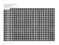
<strong>MODELS</strong>: AT/USS 14-64 to 14-96<br />
One-Cell Cooling Towers<br />
Weights (LBS) Dimensions<br />
Fan Air<br />
Model Nominal Heaviest Motor Flow<br />
No. Tonnage Shipping Operating Section✦ (HP) (CFM) H † T † P L<br />
AT 14-64 33 1,080 1,760 730 2 9,600 9' 6-1/2" 6' 5" 6' 3" 3' 11-3/4"<br />
AT 14-74 37 1,160 1,840 810 2 9,500 10' 6-1/2" 7' 5" 7' 3" 3' 11-3/4"<br />
AT 14-84 39 1,130 1,810 780 3 10,900 9' 6-1/2" 6' 5" 6' 3" 3' 11-3/4"<br />
AT 14-94 43 1,210 1,890 860 3 10,700 10' 6-1/2" 7' 5" 7' 3" 3' 11-3/4"<br />
AT 14-66 57 1,390 2,460 950 3 15,300 9' 6-1/2" 6' 5" 6' 3" 5' 11-3/4"<br />
AT 14-76 64 1,490 2,560 1,050 3 15,100 10' 6-1/2" 7' 5" 7' 3" 5' 11-3/4"<br />
AT 14-86 67 1,410 2,480 970 5 18,000 9' 6-1/2" 6' 5" 6' 3" 5' 11-3/4"<br />
AT 14-96 74 1,510 2,580 1,070 5 17,700 10' 6-1/2" 7' 5" 7' 3" 5' 11-3/4"<br />
NOTE: (1) An adequately sized bleed line must be installed in the cooling tower system to prevent build-up of impurities in the recirculated water.<br />
(2) Do not use catalog drawings for certified prints. Dimensions and weights are subject to change.<br />
(3) Adequate spacing must be allowed for access to the cooling tower. Refer to <strong>EVAPCO</strong>’s Equipment Layout Manual.<br />
(4) Nominal Tonnage is based on 3 gpm per ton at 95 degree entering water temperature, 85 degree leaving water temperature, and 78 degree wet-bulb temperature.<br />
✦ Heaviest section is upper section.<br />
† Height includes fan guard which ships factory mounted.<br />
M<br />
12-5/8<br />
4 MPT<br />
INLET<br />
24-1/8<br />
1 MPT MAKE-UP<br />
4 MPT<br />
OUTLET<br />
5-1/8<br />
4-3/8<br />
2 MPT OVERFLOW<br />
3<br />
19-3/4<br />
13<br />
5-7/8<br />
2 MPT DRAIN<br />
37-1/2<br />
25<br />
M<br />
ACCESS<br />
DOOR<br />
24-1/4<br />
38-1/4<br />
4' 1/2" L<br />
T<br />
H<br />
P<br />
M<br />
ACCESS DOOR<br />
ONE CELL
<strong>MODELS</strong>: AT/USS 14-69 to 14-912<br />
One-Cell Cooling Towers<br />
M<br />
12-5/8<br />
*MPT<br />
INLET<br />
1 MPT MAKE-UP<br />
*MPT<br />
OUTLET<br />
5-1/8<br />
4-3/8<br />
*14-69 to 14-99<br />
(1) 4" Inlet<br />
(1) 4" Outlet<br />
*14-612 to 14-912<br />
(1) 6" Inlet<br />
(1) 6" Outlet<br />
24-1/8<br />
2 MPT OVERFLOW<br />
19-3/4<br />
13<br />
5-7/8<br />
3<br />
2 MPT DRAIN<br />
T<br />
37-1/2<br />
26<br />
M<br />
ACCESS<br />
DOOR<br />
ACCESS DOOR<br />
24-1/4<br />
38-1/4<br />
4' 1/2" L<br />
H<br />
P<br />
M M<br />
M<br />
ACCESS<br />
DOOR<br />
ACCESS DOOR<br />
NOTE: (1) An adequately sized bleed line must be installed in the cooling tower system to prevent build-up of impurities in the recirculated water.<br />
(2) Do not use catalog drawings for certified prints. Dimensions and weights are subject to change.<br />
(3) Adequate spacing must be allowed for access to the cooling tower. Refer to <strong>EVAPCO</strong>’s Equipment Layout Manual.<br />
(4) Nominal Tonnage is based on 3 gpm per ton at 95 degree entering water temperature, 85 degree leaving water temperature, and 78 degree wet-bulb temperature.<br />
✦ Heaviest section is upper section.<br />
† Height includes fan guard which ships factory mounted.<br />
ENGINEERING DATA & DIMENSIONS<br />
W eights (LBS) Dimensions<br />
Fan Air<br />
Model<br />
No.<br />
Nominal<br />
Tonnage Shipping Operating<br />
Heaviest<br />
Section✦<br />
Motor<br />
(HP)<br />
Flow<br />
(CFM) H † T † P L<br />
AT 14-69 76 2,000 3,600 1,380 (2) 2 21,200 9' 6-1/2" 6' 5" 6' 3" 8' 11-3/4"<br />
AT 14-79 86 2,160 3,760 1,540 (2) 2 20,800 10' 6-1/2" 7' 5" 7' 3" 8' 11-3/4"<br />
AT 14-89 90 2,100 3,700 1,480 (2) 3 24,100 9' 6-1/2" 6' 5" 6' 3" 8' 11-3/4"<br />
AT 14-99 100 2,260 3,860 1,640 (2) 3 23,600 10' 6-1/2" 7' 5" 7' 3" 8' 11-3/4"<br />
AT 14-612 115 2,530 4,700 1,770 (2) 3 31,000 9' 6-1/2" 6' 5" 6' 3" 11' 11-3/4"<br />
AT 14-712 129 2,730 4,900 1,970 (2) 3 30,400 10' 6-1/2" 7' 5" 7' 3" 11' 11-3/4"<br />
AT 14-812 137 2,570 4,740 1,810 (2) 5 36,400 9' 6-1/2" 6' 5" 6' 3" 11' 11-3/4"<br />
AT 14-912 150 2,770 4,940 2,010 (2) 5 35,700 10' 6-1/2" 7' 5" 7' 3" 11' 11-3/4"
ENGINEERING DATA & DIMENSIONS<br />
<strong>MODELS</strong>: AT/UT/USS 19-56 to 19-98<br />
One-Cell Cooling Towers<br />
21-3/8<br />
M<br />
L<br />
2<br />
T<br />
48-1/4<br />
3/8 ✦<br />
H<br />
P<br />
23-1/8<br />
14-7/8<br />
6-1/2<br />
27<br />
3-5/8<br />
2 MPT<br />
MAKE-UP<br />
5-1/4<br />
9<br />
50-3/4<br />
3 FPT<br />
OVERFLOW<br />
3 FPT<br />
DRAIN<br />
50-3/4<br />
30-5/8<br />
M<br />
8' 5-1/2"<br />
SWING OUT RADIUS OF MOTOR COVER<br />
ACCESS DOOR<br />
M ACCESS<br />
DOOR<br />
6 BFW/GROOVED<br />
INLET<br />
6 BFW/GROOVED<br />
OUTLET<br />
Weights (LBS) Dimensions<br />
Fan Air<br />
Model<br />
No.<br />
Nominal<br />
Tonnage Shipping Operating<br />
Heaviest<br />
Section✦<br />
Motor<br />
(HP)<br />
Flow<br />
(CFM) H † T † P L<br />
AT 19-56L 89 3,000 5,040 1,950 3 22,600 10' 8-1/4" 6' 8" 7' 2-1/2" 5' 11-7/8"<br />
AT 19-56 112 3,060 5,100 2,010 5 26,500 10' 8-1/4" 6' 8" 7' 2-1/2" 5' 11-7/8"<br />
AT 19-66 123 3,100 5,140 2,050 7.5 30,200 10' 8-1/4" 6' 8" 7' 2-1/2" 5' 11-7/8"<br />
AT 19-76L 124 3,260 5,300 2,210 5 26,100 11' 8-1/4" 7' 8" 8' 2-1/2" 5' 11-7/8"<br />
AT 19-76 138 3,300 5,340 2,250 7.5 29,700 11' 8-1/4" 7' 8" 8' 2-1/2" 5' 11-7/8"<br />
AT 19-86 150 3,330 5,370 2,280 10 32,500 11' 8-1/4" 7' 8" 8' 2-1/2" 5' 11-7/8"<br />
AT 19-96L 157 3,550 5,590 2,500 10 32,000 12' 8-1/4" 8' 8" 9' 2-1/2" 5' 11-7/8"<br />
AT 19-96 171 3,620 5,660 2,570 15 36,300 12' 8-1/4" 8' 8" 9' 2-1/2" 5' 11-7/8"<br />
UT Addition ✤ 150 150 1' 1" 1' 1"<br />
AT 19-28L 109 3,390 5,810 2,220 3 26,600 10' 8-1/4" 6' 8" 7' 2-1/2" 7' 5-7/8"<br />
AT 19-28 137 3,450 5,870 2,280 5 31,300 10' 8-1/4" 6' 8" 7' 2-1/2" 7' 5-7/8"<br />
AT 19-38 148 3,490 5,910 2,320 7.5 35,700 10' 8-1/4" 6' 8" 7' 2-1/2" 7' 5-7/8"<br />
AT 19-48 159 3,520 5,940 2,350 10 39,200 10' 8-1/4" 6' 8" 7' 2-1/2" 7' 5-7/8"<br />
AT 19-58L 152 3,680 6,100 2,510 5 30,800 11' 8-1/4" 7' 8" 8' 2-1/2" 7' 5-7/8"<br />
AT 19-58 165 3,720 6,140 2,550 7.5 35,100 11' 8-1/4" 7' 8" 8' 2-1/2" 7' 5-7/8"<br />
AT 19-68 179 3,750 6,170 2,580 10 37,800 11' 8-1/4" 7' 8" 8' 2-1/2" 7' 5-7/8"<br />
AT 19-78L 173 3,990 6,410 2,820 7.5 34,500 12' 8-1/4" 8' 8" 9' 2-1/2" 7' 5-7/8"<br />
AT 19-78 187 4,020 6,440 2,850 10 37,800 12' 8-1/4" 8' 8" 9' 2-1/2" 7' 5-7/8"<br />
AT 19-88 197 3,810 6,230 2,640 15 43,700 11' 8-1/4" 7' 8" 8' 2-1/2" 7' 5-7/8"<br />
AT 19-98 207 4,080 6,500 2,910 15 43,000 12' 8-1/4" 8' 8" 9' 2-1/2" 7' 5-7/8"<br />
UT Addition ✤ 150 150 1' 5" 1' 5"<br />
NOTE: (1) An adequately sized bleed line must be installed in the cooling tower system to prevent build-up of impurities in the recirculated water.<br />
(2) Do not use catalog drawings for certified prints. Dimensions and weights are subject to change.<br />
(3) Adequate spacing must be allowed for access to the cooling tower. Refer to <strong>EVAPCO</strong>’s Equipment Layout Manual.<br />
(4) Nominal Tonnage is based on 3 gpm per ton at 95 degree entering water temperature, 85 degree leaving water temperature, and 78 degree wet-bulb temperature.<br />
✦ Outlet connection extends 3/8” beyond bottom flange.<br />
✦ Heaviest section is upper section.<br />
† Height includes fan guard which ships factory mounted.<br />
✤ Please consult the factory for additional information regarding shipping and section weight changes.<br />
ONE CELL
<strong>MODELS</strong>: AT/UT/USS 19-59 to 19-911<br />
One-Cell Cooling Towers<br />
21-3/8<br />
M<br />
8' 5-1/2"<br />
2<br />
3/8 ✦<br />
T<br />
51-7/8<br />
H<br />
Weights (LBS) Dimensions<br />
Fan Air<br />
Model Nominal Heaviest Motor Flow<br />
No. Tonnage Shipping Operating Section✦ (HP) (CFM) H † T † P L S&Q<br />
AT 19-59L 181 4,290 7,130 2,980 7.5 40,100 12' 4-3/8" 8' 1/2" 8' 7-1/8" 8' 11-1/2" 4' 5-3/4"<br />
AT 19-59 199 4,320 7,160 3,010 10 43,900 12' 4-3/8" 8' 1/2" 8' 7-1/8" 8' 11-1/2" 4' 5-3/4"<br />
AT 19-69L 178 4,050 6,890 2,740 10 44,700 11' 4-3/8" 7' 1/2" 7' 7-1/8" 8' 11-1/2" 4' 5-3/4"<br />
AT 19-69 208 4,120 6,960 2,810 15 50,800 11' 4-3/8" 7' 1/2" 7' 7-1/8" 8' 11-1/2" 4' 5-3/4"<br />
AT 19-79 232 4,390 7,230 3,080 15 49,800 12' 4-3/8" 8' 1/2" 8' 7-1/8" 8' 11-1/2" 4' 5-3/4"<br />
AT 19-89L 209 4,630 7,470 3,320 10 43,200 13' 4-3/8" 9' 1/2" 9' 7-1/8" 8' 11-1/2" 4' 5-3/4"<br />
AT 19-89 242 4,700 7,540 3,390 15 49,000 13' 4-3/8" 9' 1/2" 9' 7-1/8" 8' 11-1/2" 4' 5-3/4"<br />
AT 19-99 265 4,750 7,590 3,440 20 53,600 13' 4-3/8" 9' 1/2" 9' 7-1/8" 8' 11-1/2" 4' 5-3/4"<br />
UT Addition ✤ 150 150 1' 9" 1' 9"<br />
AT 19-111L 156 4,530 7,830 3,060 5 40,200 11' 4-3/8" 7' 1/2" 7' 7-1/8" 10' 5-1/2" 5' 2-3/4"<br />
AT 19-111 187 4,570 7,870 3,100 7.5 45,800 11' 4-3/8" 7' 1/2" 7' 7-1/8" 10' 5-1/2" 5' 2-3/4"<br />
AT 19-211 202 4,600 7,900 3,130 10 50,200 11' 4-3/8" 7' 1/2" 7' 7-1/8" 10' 5-1/2" 5' 2-3/4"<br />
AT 19-311L 202 4,890 8,190 3,420 7.5 45,100 12' 4-3/8" 8' 1/2" 8' 7-1/8" 10' 5-1/2" 5' 2-3/4"<br />
AT 19-311 221 4,920 8,220 3,450 10 49,400 12' 4-3/8" 8' 1/2" 8' 7-1/8" 10' 5-1/2" 5' 2-3/4"<br />
AT 19-411 231 4,670 7,970 3,200 15 57,100 11' 4-3/8" 7' 1/2" 7' 7-1/8" 10' 5-1/2" 5' 2-3/4"<br />
AT 19-511 256 4,990 8,290 3,520 15 56,100 12' 4-3/8" 8' 1/2" 8' 7-1/8" 10' 5-1/2" 5' 2-3/4"<br />
AT 19-611L 238 5,270 8,570 3,800 10 48,600 13' 4-3/8" 9' 1/2" 9' 7-1/8" 10' 5-1/2" 5' 2-3/4"<br />
AT 19-611 270 5,340 8,640 3,870 15 55,100 13' 4-3/8" 9' 1/2" 9' 7-1/8" 10' 5-1/2" 5' 2-3/4"<br />
AT 19-711 285 5,040 8,340 3,570 20 61,300 12' 4-3/8" 8' 1/2" 8' 7-1/8" 10' 5-1/2" 5' 2-3/4"<br />
AT 19-811 298 5,390 8,690 3,920 20 60,300 13' 4-3/8" 9' 1/2" 9' 7-1/8" 10' 5-1/2" 5' 2-3/4"<br />
AT 19-911 314 5,420 8,720 3,950 25 64,600 13' 4-3/8" 9' 1/2" 9' 7-1/8" 10' 5-1/2" 5' 2-3/4"<br />
UT Addition ✤ 150 150 1' 9" 1' 9"<br />
28<br />
P<br />
23-1/8<br />
14-7/8<br />
7-1/2<br />
ENGINEERING DATA & DIMENSIONS<br />
3 5/8<br />
2 MPT<br />
MAKE-UP<br />
5-1/4<br />
9<br />
30-5/8<br />
Q<br />
3 FPT<br />
OVERFLOW<br />
3 FPT<br />
DRAIN<br />
S<br />
M<br />
L<br />
SWING OUT RADIUS OF MOTOR COVER<br />
ACCESS DOOR<br />
M ACCESS<br />
DOOR<br />
8 BFW/GROOVED<br />
INLET<br />
8 BFW/GROOVED<br />
OUTLET<br />
NOTE: (1) An adequately sized bleed line must be installed in the cooling tower system to prevent build-up of impurities in the recirculated water.<br />
(2) Do not use catalog drawings for certified prints. Dimensions and weights are subject to change.<br />
(3) Adequate spacing must be allowed for access to the cooling tower. Refer to <strong>EVAPCO</strong>’s Equipment Layout Manual.<br />
(4) Nominal Tonnage is based on 3 gpm per ton at 95 degree entering water temperature, 85 degree leaving water temperature, and 78 degree wet-bulb temperature.<br />
✦ Outlet connection extends 3/8” beyond bottom flange.<br />
✦ Heaviest section is upper section.<br />
† Height includes fan guard which ships factory mounted.<br />
✤ Please consult the factory for additional information regarding shipping and section weight changes.
ENGINEERING DATA & DIMENSIONS<br />
<strong>MODELS</strong>: AT/UT/USS 19-412 to 19-914<br />
One-Cell Cooling Towers<br />
21-3/8<br />
M<br />
8' 5-1/2"<br />
2<br />
3/8 ✦<br />
T<br />
56-1/4<br />
H<br />
P<br />
23-1/8<br />
14-7/8<br />
29<br />
7-1/2<br />
3-5/8<br />
2 MPT<br />
MAKE-UP<br />
5-1/4<br />
9<br />
Q<br />
3 FPT<br />
OVERFLOW<br />
3 FPT<br />
DRAIN<br />
S<br />
30-5/8<br />
M<br />
L<br />
SWING OUT RADIUS OF MOTOR COVER<br />
ACCESS DOOR<br />
M ACCESS<br />
DOOR<br />
8 BFW/GROOVED<br />
INLET<br />
8 BFW/GROOVED<br />
OUTLET<br />
Weights (LBS) Dimensions<br />
Fan Air<br />
Model<br />
No.<br />
Nominal<br />
Tonnage Shipping Operating<br />
Heaviest<br />
Section✦<br />
Motor<br />
(HP)<br />
Flow<br />
(CFM) H † T † P L S&Q<br />
AT 19-412L 257 5,190 9,050 3,540 15 63,100 11' 8-3/4" 7' 1/2" 7' 11-1/2" 11' 11-3/4" 11' 11-3/4"<br />
AT 19-412 283 5,230 9,090 3,580 20 69,100 11' 8-3/4" 7' 1/2" 7' 11-1/2" 11' 11-3/4" 11' 11-3/4"<br />
AT 19-512L 256 5,470 9,330 3,820 10 54,500 12' 8-3/4" 8' 1/2" 8' 11-1/2" 11' 11-3/4" 11' 11-3/4"<br />
AT 19-512 289 5,550 9,410 3,900 15 61,900 12' 8-3/4" 8' 1/2" 8' 11-1/2" 11' 11-3/4" 11' 11-3/4"<br />
AT 19-612 319 5,590 9,450 3,940 20 67,800 12' 8-3/4" 8' 1/2" 8' 11-1/2" 11' 11-3/4" 11' 11-3/4"<br />
AT 19-712L 299 5,940 9,800 4,290 15 61,000 13' 8-3/4" 9' 1/2" 9' 11-1/2" 11' 11-3/4" 11' 11-3/4"<br />
AT 19-712 330 5,980 9,840 4,330 20 66,700 13' 8-3/4" 9' 1/2" 9' 11-1/2" 11' 11-3/4" 11' 11-3/4"<br />
AT 19-812 340 5,610 9,470 3,960 25 72,800 12' 8-3/4" 8' 1/2" 8' 11-1/2" 11' 11-3/4" 11' 11-3/4"<br />
AT 19-912 363 6,020 9,880 4,370 30 75,800 13' 8-3/4" 9' 1/2" 9' 11-1/2" 11' 11-3/4" 11' 11-3/4"<br />
UT Addition ✤ 150 150 1' 9" 1' 9"<br />
AT 19-114L 221 5,540 10,050 3,680 7.5 55,900 11' 8-3/4" 7' 1/2" 7' 11-1/2" 13' 11-3/4" 13' 11-3/4"<br />
AT 19-114 251 5,570 10,080 3,710 10 61,300 11' 8-3/4" 7' 1/2" 7' 11-1/2" 13' 11-3/4" 13' 11-3/4"<br />
AT 19-214L 249 5,950 10,460 4,090 7.5 55,100 12' 8-3/4" 8' 1/2" 8' 11-1/2" 13' 11-3/4" 13' 11-3/4"<br />
AT 19-214 280 5,980 10,490 4,120 10 60,300 12' 8-3/4" 8' 1/2" 8' 11-1/2" 13' 11-3/4" 13' 11-3/4"<br />
AT 19-314 309 5,690 10,200 3,830 20 76,500 11' 8-3/4" 7' 1/2" 7' 11-1/2" 13' 11-3/4" 13' 11-3/4"<br />
AT 19-414 315 6,060 10,570 4,200 15 68,600 12' 8-3/4" 8' 1/2" 8' 11-1/2" 13' 11-3/4" 13' 11-3/4"<br />
AT 19-514L 295 6,430 10,940 4,570 10 59,300 13' 8-3/4" 9' 1/2" 9' 11-1/2" 13' 11-3/4" 13' 11-3/4"<br />
AT 19-514 329 6,510 11,020 4,650 15 67,500 13' 8-3/4" 9' 1/2" 9' 11-1/2" 13' 11-3/4" 13' 11-3/4"<br />
AT 19-614 347 6,100 10,610 4,240 20 75,000 12' 8-3/4" 8' 1/2" 8' 11-1/2" 13' 11-3/4" 13' 11-3/4"<br />
AT 19-714 377 6,120 10,630 4,260 25 80,400 12' 8-3/4" 8' 1/2" 8' 11-1/2" 13' 11-3/4" 13' 11-3/4"<br />
AT 19-814 399 6,140 10,650 4,280 30 85,200 12' 8-3/4" 8' 1/2" 8' 11-1/2" 13' 11-3/4" 13' 11-3/4"<br />
AT 19-914 413 6,590 11,100 4,730 30 83,800 13' 8-3/4" 9' 1/2" 9' 11-1/2" 13' 11-3/4" 13' 11-3/4"<br />
UT Addition ✤ 150 150 1' 9" 1' 9"<br />
NOTE: (1) An adequately sized bleed line must be installed in the cooling tower system to prevent build-up of impurities in the recirculated water.<br />
(2) Do not use catalog drawings for certified prints. Dimensions and weights are subject to change.<br />
(3) Adequate spacing must be allowed for access to the cooling tower. Refer to <strong>EVAPCO</strong>’s Equipment Layout Manual.<br />
(4) Nominal Tonnage is based on 3 gpm per ton at 95 degree entering water temperature, 85 degree leaving water temperature, and 78 degree wet-bulb temperature.<br />
✦ Outlet connection extends 3/8” beyond bottom flange.<br />
✦ Heaviest section is upper section.<br />
† Height includes fan guard which ships factory mounted.<br />
✤ Please consult the factory for additional information regarding shipping and section weight changes.<br />
ONE CELL
<strong>MODELS</strong>: AT/UT/USS 110-112 to 110-918<br />
One-Cell Cooling Towers<br />
*110-112 to 110-912<br />
(1) 8" Inlet<br />
(1) 8" Outlet<br />
9' 9-3/4"<br />
2<br />
3/8<br />
7 †<br />
✦<br />
T<br />
62-1/4<br />
*110-118 to 110-918<br />
(1) 10" Inlet<br />
(1) 10" Outlet<br />
H<br />
P<br />
25-1/4<br />
16-7/8<br />
O<br />
3-5/8<br />
30<br />
ENGINEERING DATA & DIMENSIONS<br />
2 MPT<br />
MAKE-UP<br />
5-1/4<br />
9<br />
Q<br />
3 FPT<br />
OVERFLOW<br />
3 FPT<br />
DRAIN<br />
S<br />
L<br />
M<br />
M<br />
ACCESS DOOR<br />
ACCESS<br />
DOOR<br />
* BFW/GROOVED<br />
INLET<br />
* BFW/GROOVED<br />
OUTLET<br />
ACCESS DOOR SWINGS<br />
INSIDE UNIT<br />
Weights (LBS) Dimensions<br />
Fan Air<br />
Model Nominal Heaviest Motor Flow<br />
No. Tonnage Shipping Operating Section✦ (HP) (CFM) H † T † P O L S&Q<br />
AT 110-112L 264 6,840 12,380 4,750 10 63,700 14' 5-1/4" 9' 3" 9' 1" 7-1/4" 11' 11 3/4" 5' 11-7/8"<br />
AT 110-112 309 6,840 12,380 4,750 15 72,300 14' 5-1/4" 9' 3" 9' 1" 7-1/4" 11' 11-3/4" 5' 11-7/8"<br />
AT 110-212L 305 6,410 11,950 4,320 20 80,600 13' 5-1/4" 8' 3" 8' 1" 7-1/4" 11' 11-3/4" 5' 11-7/8"<br />
AT 110-212 326 6,460 12,000 4,370 25 86,500 13' 5-1/4" 8' 3" 8' 1" 7-1/4" 11' 11-3/4" 5' 11-7/8"<br />
AT 110-312 338 6,890 12,430 4,800 20 79,000 14' 5-1/4" 9' 3" 9' 1" 7-1/4" 11' 11-3/4" 5' 11-7/8"<br />
AT 110-412 342 6,560 12,100 4,470 30 91,700 13' 5-1/4" 8' 3" 8' 1" 7-1/4" 11' 11-3/4" 5' 11-7/8"<br />
AT 110-512 361 6,940 12,480 4,850 25 85,000 14' 5-1/4" 9' 3" 9' 1" 7-1/4" 11' 11-3/4" 5' 11-7/8"<br />
AT 110-612L 350 7,310 12,850 5,220 20 77,900 15' 5-1/4" 10' 3" 10' 1" 7-1/4" 11' 11-3/4" 5' 11-7/8"<br />
AT 110-612 373 7,360 12,900 5,270 25 83,700 15' 5-1/4" 10' 3" 10' 1" 7-1/4" 11' 11-3/4" 5' 11-7/8"<br />
AT 110-712 380 7,040 12,580 4,950 30 89800 14' 5-1/4" 9' 3" 9' 1" 7-1/4" 11' 11-3/4" 5' 11-7/8"<br />
AT 110-812 393 7,460 13,000 5,370 30 88,600 15' 5-1/4" 10' 3" 10' 1" 7-1/4" 11' 11-3/4" 5' 11-7/8"<br />
AT 110-912 410 7,710 13,250 5,620 35 92,800 15' 5-1/4" 10' 3" 10' 1" 7-1/4" 11' 11-3/4" 5' 11-7/8"<br />
UT Addition ✤ 700 700 1' 9-1/2" 1' 9-1/2"<br />
AT 110-118L 351 8,860 17,270 5,710 15 97,800 13' 5-1/4" 8' 3" 8' 0" 8-1/2" 18' 0" 9' 0"<br />
AT 110-118 389 8,910 17,320 5,760 20 107,200 13' 5-1/4" 8' 3" 8' 0" 8-1/2" 18' 0" 9' 0"<br />
AT 110-218L 364 10,180 18,590 7,030 10 83,300 15' 5-1/4" 10' 3" 10' 0" 8-1/2" 18' 0" 9' 0"<br />
AT 110-218 420 10,180 18,590 7,030 15 94,700 15' 5-1/4" 10' 3" 10' 0" 8-1/2" 18' 0" 9' 0"<br />
AT 110-318L 395 9,550 17,960 6,400 15 96,300 14' 5-1/4" 9' 3" 9' 0" 8-1/2" 18' 0" 9' 0"<br />
AT 110-318 437 9,600 18,010 6,450 20 105,500 14' 5-1/4" 9' 3" 9' 0" 8-1/2" 18' 0" 9' 0"<br />
AT 110-418 445 9,060 17,470 5,910 30 122,000 13' 5-1/4" 8' 3" 8' 0" 8-1/2" 18' 0" 9' 0"<br />
AT 110-518 471 9,650 18,060 6,500 25 113,100 14' 5-1/4" 9' 3" 9' 0" 8-1/2" 18' 0" 9' 0"<br />
AT 110-618 499 9,750 18,160 6,600 30 119,700 14' 5-1/4" 9' 3" 9' 0" 8-1/2" 18' 0" 9' 0"<br />
AT 110-718 522 10,380 18,790 7,230 30 117,800 15' 5-1/4" 10' 3" 10' 0" 8-1/2" 18' 0" 9' 0"<br />
AT 110-818 547 10,000 18,410 6,850 40 131,200 14' 5-1/4" 9' 3" 9' 0" 8-1/2" 18' 0" 9' 0"<br />
AT 110-918 570 10,630 19,040 7,480 40 129,000 15' 5-1/4" 10' 3" 10' 0" 8-1/2" 18' 0" 9' 0"<br />
UT Addition ✤ 700 700 1' 9-1/2" 1' 9-1/2"<br />
NOTE: (1) An adequately sized bleed line must be installed in the cooling tower system to prevent build-up of impurities in the recirculated water.<br />
(2) Do not use catalog drawings for certified prints. Dimensions and weights are subject to change.<br />
(3) Adequate spacing must be allowed for access to the cooling tower. Refer to <strong>EVAPCO</strong>’s Equipment Layout Manual.<br />
(4) Nominal Tonnage is based on 3 gpm per ton at 95 degree entering water temperature, 85 degree leaving water temperature, and 78 degree wet-bulb temperature.<br />
✦ Outlet connection extends 3/8” beyond bottom flange.<br />
✦ Heaviest section is upper section.<br />
† Height does not include fan guard. Consult factory for whether or not fan guard ships mounted.<br />
✤ Please consult the factory for additional information regarding shipping and section weight changes.
ENGINEERING DATA & DIMENSIONS<br />
<strong>MODELS</strong>: AT/UT/USS 112-012 to 112-914<br />
One-Cell Cooling Towers<br />
2 MPT<br />
MAKE-UP<br />
25-1/4<br />
16-7/8<br />
O<br />
3-5/8<br />
5-1/4<br />
9<br />
* BFW/GROOVED<br />
INLET<br />
3 FPT<br />
OVERFLOW<br />
3 FPT DRAIN<br />
S<br />
L<br />
M<br />
M<br />
ACCESS DOOR<br />
ACCESS<br />
DOOR<br />
Q<br />
* BFW/GROOVED<br />
OUTLET<br />
ACCESS DOOR SWINGS INSIDE UNIT<br />
P<br />
31<br />
H<br />
✦<br />
T<br />
7<br />
2<br />
3/8<br />
†<br />
*112-012 to 112-912<br />
(1) 8” Inlet<br />
(1) 8” Outlet<br />
*112-314 to 112-914<br />
(1) 10” Inlet<br />
(1) 10” Outlet<br />
Weights (LBS) Dimensions<br />
Fan Air<br />
Model<br />
No.<br />
Nominal<br />
Tonnage Shipping Operating<br />
Heaviest<br />
Section✦<br />
Motor<br />
(HP)<br />
Flow<br />
(CFM) H<br />
NOTE: (1) An adequately sized bleed line must be installed in the cooling tower system to prevent build-up of impurities in the recirculated water.<br />
(2) Do not use catalog drawings for certified prints. Dimensions and weights are subject to change.<br />
(3) Adequate spacing must be allowed for access to the cooling tower. Refer to <strong>EVAPCO</strong>’s Equipment Layout Manual.<br />
(4) Nominal Tonnage is based on 3 gpm per ton at 95 degree entering water temperature, 85 degree leaving water temperature, and 78 degree wet-bulb temperature.<br />
✦ Outlet connection extends 3/8” beyond bottom flange.<br />
✦ Heaviest section is upper section.<br />
† Height does not include fan guard. Consult factory for whether or not fan guard ships mounted.<br />
✤ Please consult the factory for additional information regarding shipping and section weight changes.<br />
† T † P O L S&Q<br />
AT 112-012L 280 7,370 13,580 4,930 10 71,600 13' 6-1/4" 8' 4" 8' 2" 7-1/4 11' 11-3/4" 5' 11-7/8"<br />
AT 112-012 334 7,440 13,650 5,000 15 81,400 13' 6-1/4" 8' 4" 8' 2" 7-1/4 11' 11-3/4" 5' 11-7/8"<br />
AT 112-112 364 7,490 13,700 5,050 20 89,300 13' 6-1/4" 8' 4" 8' 2" 7-1/4 11' 11-3/4" 5' 11-7/8"<br />
AT 112-212 391 7,540 13,750 5,100 25 95,800 13' 6-1/4" 8' 4" 8' 2" 7-1/4 11' 11-3/4" 5' 11-7/8"<br />
AT 112-312L 370 7,980 14,190 5,540 15 80,000 14' 6-1/4" 9' 4" 9' 2" 7-1/4 11' 11-3/4" 5' 11-7/8"<br />
AT 112-312 404 8,030 14,240 5,590 20 87,700 14' 6-1/4" 9' 4" 9' 2" 7-1/4 11' 11-3/4" 5' 11-7/8"<br />
AT 112-412 414 7,640 13,850 5,200 30 101,500 13' 6-1/4" 8' 4" 8' 2" 7-1/4 11' 11-3/4" 5' 11-7/8"<br />
AT 112-512L 387 8,470 14,680 6,030 15 78,700 15' 6-1/4" 10' 4" 10' 2" 7-1/4 11' 11-3/4" 5' 11-7/8"<br />
AT 112-512 422 8,520 14,730 6,080 20 86,300 15' 6-1/4" 10' 4" 10' 2" 7-1/4 11' 11-3/4" 5' 11-7/8"<br />
AT 112-612 434 8,080 14,290 5,640 25 94,000 14' 6-1/4" 9' 4" 9' 2" 7-1/4 11' 11-3/4" 5' 11-7/8"<br />
AT 112-712 461 8,180 14,390 5,740 30 99,500 14' 6-1/4" 9' 4" 9' 2" 7-1/4 11' 11-3/4" 5' 11-7/8"<br />
AT 112-812 481 8,670 14,880 6,230 30 97,900 15' 6-1/4" 10' 4" 10' 2" 7-1/4 11' 11-3/4" 5' 11-7/8"<br />
AT 112-912 515 8,920 15,130 6,480 40 107,100 15' 6-1/4" 10' 4" 10' 2" 7-1/4 11' 11-3/4" 5' 11-7/8"<br />
UT Addition ✤ 700 700 1' 9-1/2" 1' 9-1/2"<br />
AT 112-314L 425 8,200 15,530 5,550 25 104,100 14'-1/4" 8' 4" 8' 7" 8-1/2 13' 11-3/4" 6' 11-7/8"<br />
AT 112-314 450 8,270 15,600 5,620 30 110,400 14'-1/4" 8' 4" 8' 7" 8-1/2 13' 11-3/4" 6' 11-7/8"<br />
AT 112-414L 439 8,800 16,130 6,150 20 95,400 15'-1/4" 9' 4" 9' 7" 8-1/2 13' 11-3/4" 6' 11-7/8"<br />
AT 112-414 471 8,860 16,190 6,210 25 102,300 15'-1/4" 9' 4" 9' 7" 8-1/2 13' 11-3/4" 6' 11-7/8"<br />
AT 112-514L 460 9,320 16,650 6,670 20 93,800 16'-1/4" 10' 4" 10' 7" 8-1/2 13' 11-3/4" 6' 11-7/8"<br />
AT 112-514 494 9,380 16,710 6,730 25 100,600 16'-1/4" 10' 4" 10' 7" 8-1/2 13' 11-3/4" 6' 11-7/8"<br />
AT 112-614 501 8,930 16,260 6,280 30 108,300 15'-1/4" 9' 4" 9' 7" 8-1/2 13' 11-3/4" 6' 11-7/8"<br />
AT 112-714 524 9,450 16,780 6,800 30 106,600 16'-1/4" 10' 4" 10' 7" 8-1/2 13' 11-3/4" 6' 11-7/8"<br />
AT 112-814 548 9,190 16,520 6,540 40 118,600 15'-1/4" 9' 4" 9' 7" 8-1/2 13' 11-3/4" 6' 11-7/8"<br />
AT 112-914 574 9,710 17,040 7,060 40 116,600 16'-1/4" 10' 4" 10' 7" 8-1/2 13' 11-3/4" 6' 11-7/8"<br />
UT Addition ✤ 700 700 1' 9-1/2" 1' 9-1/2"<br />
11' 10"<br />
ONE CELL
<strong>MODELS</strong>: AT/UT/USS 112-018 to 112-920<br />
One-Cell Cooling Towers<br />
11' 10"<br />
2<br />
7 †<br />
T<br />
74-1/4<br />
3/8<br />
✦<br />
H<br />
P<br />
25-1/4<br />
16-7/8<br />
8-1/2<br />
3-5/8<br />
32<br />
2 MPT<br />
MAKE-UP<br />
5-1/4<br />
9<br />
ENGINEERING DATA & DIMENSIONS<br />
ACCESS DOOR SWINGS INSIDE UNIT<br />
Q<br />
3 FPT OVERFLOW<br />
3 FPT DRAIN<br />
S<br />
L<br />
ACCESS DOOR<br />
M<br />
M<br />
ACCESS<br />
DOOR<br />
10 BFW/GROOVED<br />
INLET<br />
10 BFW/GROOVED<br />
OUTLET<br />
Weights (LBS) Dimensions<br />
Fan Air<br />
Model<br />
No.<br />
Nominal<br />
Tonnage Shipping Operating<br />
Heaviest<br />
Section✦<br />
Motor<br />
(HP)<br />
Flow<br />
(CFM) H † T † P L S&Q<br />
AT 112-018L 497 10,320 19,590 6,760 20 120,600 14' 6 1/4" 8' 4" 9' 1" 18' 0" 9' 0"<br />
AT 112-018 525 10,370 19,640 6,810 25 129,600 14' 6 1/4" 8' 4" 9' 1" 18' 0" 9' 0"<br />
AT 112-118 554 10,480 19,750 6,920 30 137,400 14' 6 1/4" 8' 4" 9' 1" 18' 0" 9' 0"<br />
AT 112-218L 546 11,100 20,370 7,540 20 118,700 15' 6 1/4" 9' 4" 10' 1" 18' 0" 9' 0"<br />
AT 112-218 581 11,150 20,420 7,590 25 127,400 15' 6 1/4" 9' 4" 10' 1" 18' 0" 9' 0"<br />
AT 112-318 614 11,260 20,530 7,700 30 135,000 15' 6 1/4" 9' 4" 10' 1" 18' 0" 9' 0"<br />
AT 112-418L 606 11,890 21,160 8,330 25 125,400 16' 6 1/4" 10' 4" 11' 1" 18' 0" 9' 0"<br />
AT 112-418 642 12,000 21,270 8,440 30 132,900 16' 6 1/4" 10' 4" 11' 1" 18' 0" 9' 0"<br />
AT 112-518 675 11,520 20,790 7,960 40 147,700 15' 6 1/4" 9' 4" 10' 1" 18' 0" 9' 0"<br />
AT 112-618 705 12,260 21,530 8,700 40 145,300 16' 6 1/4" 10' 4" 11' 1" 18' 0" 9' 0"<br />
AT 112-718 724 11,580 20,850 8,020 50 158,500 15' 6 1/4" 9' 4" 10' 1" 18' 0" 9' 0"<br />
AT 112-818 757 12,320 21,590 8,760 50 155,600 16' 6 1/4" 10' 4" 11' 1" 18' 0" 9' 0"<br />
AT 112-918 785 12,430 21,700 8,870 60 165,000 16' 6 1/4" 10' 4" 11' 1" 18' 0" 9' 0"<br />
UT Addition ✤ 1,200 1,200 1' 3-1/2" 1' 3-1/2"<br />
AT 112-520L 625 11,440 21,840 7,630 40 154,100 14' 6 1/4" 8' 4" 9' 1" 20' 0" 10' 0"<br />
AT 112-520 679 11,500 21,900 7,690 50 165,300 14' 6 1/4" 8' 4" 9' 1" 20' 0" 10' 0"<br />
AT 112-620L 655 12,810 23,210 9,000 30 136,100 16' 6 1/4" 10' 4" 11' 1" 20' 0" 10' 0"<br />
AT 112-620 728 13,070 23,470 9,260 40 148,800 16' 6 1/4" 10' 4" 11' 1" 20' 0" 10' 0"<br />
AT 112-720L 698 12,170 22,570 8,360 40 151,200 15' 6 1/4" 9' 4" 10' 1" 20' 0" 10' 0"<br />
AT 112-720 757 12,230 22,630 8,420 50 162,200 15' 6 1/4" 9' 4" 10' 1" 20' 0" 10' 0"<br />
AT 112-820 788 13,130 23,530 9,320 50 159,500 16' 6 1/4" 10' 4" 11' 1" 20' 0" 10' 0"<br />
AT 112-920 817 13,240 23,640 9,430 60 169,100 16' 6 1/4" 10' 4" 11' 1" 20' 0" 10' 0"<br />
UT Addition ✤ 1,200 1,200 1' 3-1/2" 1' 3-1/2"<br />
NOTE: (1) An adequately sized bleed line must be installed in the cooling tower system to prevent build-up of impurities in the recirculated water.<br />
(2) Do not use catalog drawings for certified prints. Dimensions and weights are subject to change.<br />
(3) Adequate spacing must be allowed for access to the cooling tower. Refer to <strong>EVAPCO</strong>’s Equipment Layout Manual.<br />
(4) Nominal Tonnage is based on 3 gpm per ton at 95 degree entering water temperature, 85 degree leaving water temperature, and 78 degree wet-bulb temperature.<br />
✦ Outlet connection extends 3/8” beyond bottom flange.<br />
✦ Heaviest section is upper section.<br />
† Height does not include fan guard. Consult factory for whether or not fan guard ships mounted.<br />
✤ Please consult the factory for additional information regarding shipping and section weight changes.
ENGINEERING DATA & DIMENSIONS<br />
<strong>MODELS</strong>: AT/UT/USS 114-0124 to 114-1324<br />
One-Cell Cooling Towers<br />
13' 11-1/4"<br />
2<br />
26<br />
3/8<br />
✦<br />
7<br />
†<br />
T<br />
99-3/8<br />
H<br />
P<br />
17-3/8<br />
4 FPT<br />
OVERFLOW<br />
9<br />
4-1/8<br />
33<br />
9<br />
4 FPT<br />
DRAIN<br />
72-1/4<br />
142-1/2<br />
142-1/2<br />
3 MPT<br />
MAKE-UP<br />
23' 9"<br />
M<br />
M<br />
ACCESS<br />
DOOR<br />
ACCESS<br />
DOOR<br />
14 BFW/GOOVED<br />
INLET<br />
14 BFW/GROOVED<br />
OUTLET<br />
ACCESS DOOR<br />
SWINGS MOUNT INSIDE<br />
Weights (LBS) Dimensions<br />
Fan Air<br />
Model Nominal Heaviest Motor Flow<br />
No. Tonnage Shipping Operating Section✦ (HP) (CFM) H † T † P<br />
AT 114-0124L 684 16,490 32,340 10,650 25 170,100 17' 5-5/8" 9' 2-1/4" 11' 3-7/8"<br />
AT 114-0124 722 16,510 32,360 10,670 30 180,300 17' 5-5/8" 9' 2-1/4" 11' 3-7/8"<br />
AT 114-0224 781 16,660 32,510 10,820 40 197,600 17' 5-5/8" 9' 2-1/4" 11' 3-7/8"<br />
AT 114-0324L 772 18,520 34,370 12,680 25 152,100 19' 5-5/8" 11' 2-1/4" 13' 3-7/8"<br />
AT 114-0324 834 18,570 34,420 12,730 25 163,200 19' 5-5/8" 11' 2-1/4" 13' 3-7/8"<br />
AT 114-0424 839 17,010 32,860 11,170 50 212,300 17' 5-5/8" 9' 2-1/4" 11' 3-7/8"<br />
AT 114-0524 872 18,590 34,440 12,750 30 173,400 19' 5-5/8" 11' 2-1/4" 13' 3-7/8"<br />
AT 114-0624L 812 17,550 33,400 11,710 30 177,400 18' 5-5/8" 10' 2-1/4" 12' 3-7/8"<br />
AT 114-0624 892 17,700 33,550 11,860 40 194,100 18' 5-5/8" 10' 2-1/4" 12' 3-7/8"<br />
AT 114-0724 947 18,740 34,590 12,900 40 190,900 19' 5-5/8" 11' 2-1/4" 13' 3-7/8"<br />
AT 114-0824 951 18,050 33,900 12,210 50 208,500 18' 5-5/8" 10' 2-1/4" 12' 3-7/8"<br />
AT 114-0924 998 19,090 34,940 13,250 50 205,000 19' 5-5/8" 11' 2-1/4" 13' 3-7/8"<br />
AT 114-1024 1,008 18,220 34,070 12,380 60 220,600 18' 5-5/8" 10' 2-1/4" 12' 3-7/8"<br />
AT 114-1124 1,056 19,260 35,110 13,420 60 217,100 19' 5-5/8" 11' 2-1/4" 13' 3-7/8"<br />
AT 114-1224 1,135 19,500 35,350 13,660 75 238,000 19' 5-5/8" 11' 2-1/4" 13' 3-7/8"<br />
AT 114-1324** 1,201 19,940 35,790 14,100 100 255,100 19' 5-5/8" 11' 2-1/4" 13' 3-7/8"<br />
UT Addition ✤ 1,250 1,250 1' 1-1/2" 1' 1-1/2"<br />
NOTE: (1) An adequately sized bleed line must be installed in the cooling tower system to prevent build-up of impurities in the recirculated water.<br />
(2) Do not use catalog drawings for certified prints. Dimensions and weights are subject to change.<br />
(3) Adequate spacing must be allowed for access to the cooling tower. Refer to <strong>EVAPCO</strong>’s Equipment Layout Manual.<br />
(4) Nominal Tonnage is based on 3 gpm per ton at 95 degree entering water temperature, 85 degree leaving water temperature, and 78 degree wet-bulb temperature.<br />
✦ Outlet connection extends 3/8” beyond bottom flange.<br />
✦ Heaviest section is upper section.<br />
† Height does not include fan guard. Consult factory for whether or not fan guard ships mounted.<br />
✤ Please consult the factory for additional information regarding shipping and section weight changes.<br />
** Model available with gear drive only. Motor and access door located on 13’ 11-1/4” unit end. Super Low Sound Fan is not available on this unit.<br />
ONE CELL
<strong>MODELS</strong>: AT/UT/USS 114-526 to 114-926<br />
One-Cell Cooling Towers<br />
13' 11-1/4"<br />
7†<br />
2<br />
26<br />
3/8<br />
T<br />
123-3/8<br />
✦<br />
H<br />
P<br />
17-3/8<br />
9<br />
4 FPT<br />
OVERFLOW<br />
4-1/8<br />
34<br />
9<br />
ENGINEERING DATA & DIMENSIONS<br />
ACCESS<br />
DOOR<br />
4 FPT<br />
DRAIN<br />
78-1/4<br />
ACCESS DOOR<br />
154-1/2<br />
154-1/2<br />
M M<br />
M M<br />
3 MPT<br />
MAKE-UP<br />
25' 8-7/8"<br />
ACCESS DOORS<br />
SWING INSIDE UNIT<br />
ACCESS DOOR<br />
14 BFW/GROOVED<br />
INLET<br />
14 BFW/GROOVED<br />
OUTLET<br />
Weights (LBS) Dimensions<br />
Fan Air<br />
Model<br />
No.<br />
Nominal<br />
Tonnage Shipping Operating<br />
Heaviest<br />
Section✦<br />
Motor<br />
(HP)<br />
Flow<br />
(CFM) H † T † P<br />
AT 114-526 1,003 24,800 41,630 17,660 (2)20 200,200 22' 3-1/2" 12' 1/8" 16' 3-3/4"<br />
AT 114-626 1,078 24,860 41,690 17,720 (2)25 214,700 22' 3-1/2" 12' 1/8" 16' 3-3/4"<br />
AT 114-726 1,142 24,960 41,790 17,820 (2)30 227,300 22' 3-1/2" 12' 1/8" 16' 3-3/4"<br />
AT 114-826 1,247 25,280 42,110 18,140 (2)40 248,500 22' 3-1/2" 12' 1/8" 16' 3-3/4"<br />
AT 114-926 1,332 25,300 42,130 18,160 (2)50 266,300 22' 3-1/2" 12' 1/8" 16' 3-3/4"<br />
UT Addition ✤ 2,400 ✤ 1' 3-1/2" 1' 3-1/2"<br />
NOTE: (1) An adequately sized bleed line must be installed in the cooling tower system to prevent build-up of impurities in the recirculated water.<br />
(2) Do not use catalog drawings for certified prints. Dimensions and weights are subject to change.<br />
(3) Adequate spacing must be allowed for access to the cooling tower. Refer to <strong>EVAPCO</strong>’s Equipment Layout Manual.<br />
(4) Nominal Tonnage is based on 3 gpm per ton at 95 degree entering water temperature, 85 degree leaving water temperature, and 78 degree wet-bulb temperature.<br />
✦ Outlet connection extends 3/8” beyond bottom flange.<br />
✦ Heaviest section is upper section.<br />
† Height does not include fan guard. Consult factory for whether or not fan guard ships mounted.<br />
✤ Please consult the factory for additional information regarding shipping and section weight changes.<br />
ACCESS<br />
DOOR
ENGINEERING DATA & DIMENSIONS<br />
<strong>MODELS</strong>: AT/UT/USS 26-517 to 28-917<br />
Two-Cell Cooling Towers<br />
21-3/8<br />
M<br />
W 3/8<br />
2<br />
T<br />
✦<br />
H<br />
P<br />
23-1/8<br />
14-7/8<br />
6-1/2<br />
3-5/8<br />
35<br />
50-3/4<br />
50-3/4<br />
30-5/8 30-5/8<br />
M<br />
92-1/2<br />
SWING OUT RADIUS<br />
OF MOTOR COVER<br />
ACCESS DOOR<br />
ACCESS<br />
DOOR<br />
5-1/4<br />
101-3/8 2-1/2<br />
17' 1-1/2"<br />
(2) 3 FPT<br />
OVERFLOW<br />
(2) 3 FPT<br />
DRAIN<br />
(2) 2 MPT<br />
MAKE-UP<br />
M<br />
M M<br />
ACCESS DOOR<br />
ACCESS<br />
DOOR<br />
(2) 6 BFW/GROOVED<br />
INLET<br />
(2) 6 BFW/GROOVED<br />
OUTLET<br />
Weights (LBS) Dimensions<br />
Fan Air<br />
Model<br />
No.<br />
Nominal<br />
Tonnage Shipping Operating<br />
Heaviest<br />
Section✦<br />
Motor<br />
(HP)<br />
Flow<br />
(CFM) H † T † P W<br />
AT 26-517L 179 6,080 10,160 1,990 (2)3 45,200 10' 11-7/8" 6' 8" 7' 6" 5' 11-7/8"<br />
AT 26-517 225 6,120 10,200 2,010 (2)5 53,100 10' 11-7/8" 6' 8" 7' 6" 5' 11-7/8"<br />
AT 26-617 247 6,200 10,280 2,050 (2)7.5 60,500 10' 11-7/8" 6' 8" 7' 6" 5' 11-7/8"<br />
AT 26-717L 250 6,520 10,600 2,210 (2)5 52,300 11' 11-7/8" 7' 8" 8' 6" 5' 11-7/8"<br />
AT 26-717 277 6,600 10,680 2,250 (2)7.5 59,400 11' 11-7/8" 7' 8" 8' 6" 5' 11-7/8"<br />
AT 26-817 302 6,660 10,740 2,280 (2)10 65,100 11' 11-7/8" 7' 8" 8' 6" 5' 11-7/8"<br />
AT 26-917L 315 7,100 11,180 2,500 (2)10 64,000 12' 11-7/8" 8' 8" 9' 6" 5' 11-7/8"<br />
AT 26-917 344 7,240 11,320 2,570 (2)15 72,800 12' 11-7/8" 8' 8" 9' 6" 5' 11-7/8"<br />
UT Addition ✤ 300 150 1' 1" 1' 1"<br />
AT 28-217L 217 6,860 11,700 2,260 (2)3 53,200 11' 4-1/4" 6' 8" 7' 10-1/2" 7' 5-7/8"<br />
AT 28-217 274 6,900 11,740 2,280 (2)5 62,600 11' 4-1/4" 6' 8" 7' 10-1/2" 7' 5-7/8"<br />
AT 28-317 297 6,980 11,820 2,320 (2)7.5 71,400 11' 4-1/4" 6' 8" 7' 10-1/2" 7' 5-7/8"<br />
AT 28-417 319 7,040 11,880 2,350 (2)10 78,300 11' 4-1/4" 6' 8" 7' 10-1/2" 7' 5-7/8"<br />
AT 28-517L 304 7,360 12,200 2,510 (2)5 61,600 12' 4-1/4" 7' 8" 8' 10-1/2" 7' 5-7/8"<br />
AT 28-517 331 7,440 12,280 2,550 (2)7.5 70,200 12' 4-1/4" 7' 8" 8' 10-1/2" 7' 5-7/8"<br />
AT 28-617 358 7,500 12,340 2,580 (2)10 76,900 12' 4-1/4" 7' 8" 8' 10-1/2" 7' 5-7/8"<br />
AT 28-717L 346 7,980 12,820 2,820 (2)7.5 69,100 13' 4-1/4" 8' 8" 9' 10-1/2" 7' 5-7/8"<br />
AT 28-717 373 8,040 12,880 2,850 (2)10 75,700 13' 4-1/4" 8' 8" 9' 10-1/2" 7' 5-7/8"<br />
AT 28-817 393 7,620 12,460 2,640 (2)15 87,500 12' 4-1/4" 7' 8" 8' 10-1/2" 7' 5-7/8"<br />
AT 28-917 414 8,160 13,000 2,910 (2)15 86,000 13' 4-1/4" 8' 8" 9' 10-1/2" 7' 5-7/8"<br />
UT Addition ✤ 300 150 1' 5" 1' 5"<br />
NOTE: (1) An adequately sized bleed line must be installed in the cooling tower system to prevent build-up of impurities in the recirculated water.<br />
(2) Do not use catalog drawings for certified prints. Dimensions and weights are subject to change.<br />
(3) Adequate spacing must be allowed for access to the cooling tower. Refer to <strong>EVAPCO</strong>’s Equipment Layout Manual.<br />
(4) These models are available as (2) independent operating cells. Consult the factory for details.<br />
(5) Nominal Tonnage is based on 3 gpm per ton at 95 degree entering water temperature, 85 degree leaving water temperature, and 78 degree wet-bulb temperature.<br />
✦ Outlet connection extends 3/8” beyond bottom flange.<br />
✦ Heaviest section is upper section.<br />
† Height includes fan guard which ships factory mounted.<br />
✤ Please consult the factory for additional information regarding shipping and section weight changes.<br />
TWO CELL
<strong>MODELS</strong>: AT/UT/USS 29-318 to 29-921<br />
Two-Cell Cooling Towers<br />
21-3/8<br />
M<br />
8' 5 -1/2"<br />
2<br />
3/8<br />
✦<br />
T<br />
60-1/4<br />
H<br />
P<br />
23-1/8<br />
14-7/8<br />
7-1/2<br />
3-5/8<br />
36<br />
2 MPT<br />
MAKE-UP<br />
9<br />
5-1/4<br />
ENGINEERING DATA & DIMENSIONS<br />
Q<br />
3 FPT<br />
OVERFLOW<br />
3 FPT DRAIN<br />
S<br />
30-5/8<br />
SWING OUT RADIUS<br />
OF MOTOR COVER<br />
ACCESS<br />
DOOR<br />
ACCESS<br />
DOOR<br />
(2) 8 BFW/GROOVED INLET<br />
(2) 8 BFW/GROOVED OUTLET<br />
L<br />
30-5/8<br />
M M<br />
M M<br />
ACCESS<br />
DOOR<br />
Weights (LBS) Dimensions<br />
Fan Air<br />
Model<br />
No.<br />
Nominal<br />
Tonnage Shipping Operating<br />
Heaviest<br />
Section✦<br />
Motor<br />
(HP)<br />
Flow<br />
(CFM) H<br />
NOTE: (1) An adequately sized bleed line must be installed in the cooling tower system to prevent build-up of impurities in the recirculated water.<br />
(2) Do not use catalog drawings for certified prints. Dimensions and weights are subject to change.<br />
(3) Adequate spacing must be allowed for access to the cooling tower. Refer to <strong>EVAPCO</strong>’s Equipment Layout Manual.<br />
(4) These models are available as (2) independent operating cells. Consult the factory for details.<br />
(5) Nominal Tonnage is based on 3 gpm per ton at 95 degree entering water temperature, 85 degree leaving water temperature, and 78 degree wet-bulb temperature.<br />
✦ Outlet connection extends 3/8” beyond bottom flange.<br />
✦ Heaviest section is upper section.<br />
† Height includes fan guard which ships factory mounted.<br />
✤ Please consult the factory for additional information regarding shipping and section weight changes.<br />
† T † P L S&Q<br />
AT 29-318L 274 7,840 13,730 5,290 (2) 5 72,000 12' 3/4" 7' 1/2" 8' 3-1/2" 18' 0" 4' 5-3/4"<br />
AT 29-318 329 7,920 13,810 5,370 (2) 7.5 81,900 12' 3/4" 7' 1/2" 8' 3-1/2" 18' 0" 4' 5-3/4"<br />
AT 29-418 362 7,980 13,870 5,430 (2) 10 89,800 12' 3/4" 7' 1/2" 8' 3-1/2" 18' 0" 4' 5-3/4"<br />
AT 29-518L 368 8,450 14,340 5,900 (2) 7.5 80,600 13' 3/4" 8' 1/2" 9' 3-1/2" 18' 0" 4' 5-3/4"<br />
AT 29-518 404 8,510 14,400 5,960 (2) 10 88,200 13' 3/4" 8' 1/2" 9' 3-1/2" 18' 0" 4' 5-3/4"<br />
AT 29-618 422 8,120 14,010 5,570 (2) 15 102,000 12' 3/4" 7' 1/2" 8' 3-1/2" 18' 0" 4' 5-3/4"<br />
AT 29-718 471 8,650 14,540 6,100 (2) 15 100,100 13' 3/4" 8' 1/2" 9' 3-1/2" 18' 0" 4' 5-3/4"<br />
AT 29-818L 425 9,090 14,980 6,540 (2) 10 86,800 14' 3/4" 9' 1/2" 10' 3-1/2" 18' 0" 4' 5-3/4"<br />
AT 29-818 491 9,230 15,120 6,680 (2) 15 98,400 14' 3/4" 9' 1/2" 10' 3-1/2" 18' 0" 4' 5-3/4"<br />
AT 29-918 538 9,330 15,220 6,780 (2) 20 107,600 14' 3/4" 9' 1/2" 10' 3-1/2" 18' 0" 4' 5-3/4"<br />
UT Addition ✤ 300 300 1' 9" 1' 9"<br />
AT 29-121L 315 8,920 15,860 6,130 (2) 5 80,700 12' 3/4" 7' 1/2" 8' 3-1/2" 21' 0" 5' 2-3/4"<br />
AT 29-121 379 9,000 15,940 6,210 (2) 7.5 91,800 12' 3/4" 7' 1/2" 8' 3-1/2" 21' 0" 5' 2-3/4"<br />
AT 29-221L 347 9,530 16,470 6,740 (2) 5 79,600 13' 3/4" 8' 1/2" 9' 3-1/2" 21' 0" 5' 2-3/4"<br />
AT 29-221 410 9,610 16,550 6,820 (2) 7.5 90,500 13' 3/4" 8' 1/2" 9' 3-1/2" 21' 0" 5' 2-3/4"<br />
AT 29-321 448 9,670 16,610 6,880 (2) 10 99,200 13' 3/4" 8' 1/2" 9' 3-1/2" 21' 0" 5' 2-3/4"<br />
AT 29-421 467 9,200 16,140 6,410 (2) 15 114,600 12' 3/4" 7' 1/2" 8' 3-1/2" 21' 0" 5' 2-3/4"<br />
AT 29-521L 445 10,270 17,210 7,480 (2) 7.5 88,900 14' 3/4" 9' 1/2" 10' 3-1/2" 21' 0" 5' 2-3/4"<br />
AT 29-521 482 10,330 17,270 7,540 (2) 10 97,500 14' 3/4" 9' 1/2" 10' 3-1/2" 21' 0" 5' 2-3/4"<br />
AT 29-621 518 9,810 16,750 7,020 (2) 15 112,500 13' 3/4" 8' 1/2" 9' 3-1/2" 21' 0" 5' 2-3/4"<br />
AT 29-721 547 10,470 17,410 7,680 (2) 15 110,700 14' 3/4" 9' 1/2" 10' 3-1/2" 21' 0" 5' 2-3/4"<br />
AT 29-821 578 9,910 16,850 7,120 (2) 20 123,000 13' 3/4" 8' 1/2" 9' 3-1/2" 21' 0" 5' 2-3/4"<br />
AT 29-921 636 10,630 17,570 7,840 (2) 25 129,800 14' 3/4" 9' 1/2" 10' 3-1/2" 21' 0" 5' 2-3/4"<br />
UT Addition ✤ 300 300 1' 9" 1' 9"<br />
ACCESS<br />
DOOR<br />
Q<br />
S
ENGINEERING DATA & DIMENSIONS<br />
<strong>MODELS</strong>: AT/UT/USS 29-024 to 29-928<br />
Two-Cell Cooling Towers<br />
21-3/8<br />
M<br />
8' 5-1/2" 3/8<br />
2<br />
T<br />
✦<br />
H<br />
P<br />
23-1/8<br />
14-7/8<br />
7-1/2<br />
3-5/8<br />
Q<br />
S<br />
37<br />
30-5/8<br />
Swing Out Radius of Motor Cover<br />
ACCESS DOOR<br />
ACCESS<br />
DOOR<br />
L<br />
30-5/8<br />
M M<br />
M M<br />
(2) 3 FPT OVERFLOW<br />
(2) 3 FPT DRAIN<br />
N<br />
(2) 2 MPT MAKE-UP<br />
5-1/4<br />
M 2-1/2<br />
ACCESS DOOR<br />
ACCESS<br />
DOOR<br />
(2) 8 BFW/GROOVED<br />
INLET<br />
(2) 8 BFW/GROOVED<br />
OUTLET<br />
Weights (LBS) Dimensions<br />
Fan Air<br />
Model<br />
No.<br />
Nominal<br />
Tonnage Shipping Operating<br />
Heaviest<br />
Section✦<br />
Motor<br />
(HP)<br />
Flow<br />
(CFM) H † T † P L M N S&Q<br />
AT 29-024L 452 10,860 18,580 3,790 (2) 7.5 98,600 13' 3/4" 8' 1/2" 9' 3-1/2" 24' 2" 11' 11-3/4" 11' 2-3/4" 5' 11-7/8"<br />
AT 29-024 506 10,920 18,640 3,820 (2) 10 107,900 13' 3/4" 8' 1/2" 9' 3-1/2" 24' 2" 11' 11-3/4" 11' 2-3/4" 5' 11-7/8"<br />
AT 29-124L 481 11,640 19,360 4,180 (2) 7.5 96,900 14' 3/4" 9' 1/2" 10' 3-1/2" 24' 2" 11' 11-3/4" 11' 2-3/4" 5' 11-7/8"<br />
AT 29-124 531 11,700 19,420 4,210 (2) 10 106,200 14' 3/4" 9' 1/2" 10' 3-1/2" 24' 2" 11' 11-3/4" 11' 2-3/4" 5' 11-7/8"<br />
AT 29-224L 507 10,360 18,080 3,540 (2) 15 124,900 12' 3/4" 7' 1/2" 8' 3-1/2" 24' 2" 11' 11-3/4" 11' 2-3/4" 5' 11-7/8"<br />
AT 29-224 559 10,440 18,160 3,580 (2) 20 137,000 12' 3/4" 7' 1/2" 8' 3-1/2" 24' 2" 11' 11-3/4" 11' 2-3/4" 5' 11-7/8"<br />
AT 29-324 571 11,080 18,800 3,900 (2) 15 122,600 13' 3/4" 8' 1/2" 9' 3-1/2" 24' 2" 11' 11-3/4" 11' 2-3/4" 5' 11-7/8"<br />
AT 29-424 593 11,860 19,580 4,290 (2) 15 120,700 14' 3/4" 9' 1/2" 10' 3-1/2" 24' 2" 11' 11-3/4" 11' 2-3/4" 5' 11-7/8"<br />
AT 29-524 630 11,160 18,880 3,940 (2) 20 134,100 13' 3/4" 8' 1/2" 9' 3-1/2" 24' 2" 11' 11-3/4" 11' 2-3/4" 5' 11-7/8"<br />
AT 29-624 653 11,940 19,660 4,330 (2) 20 132,100 14' 3/4" 9' 1/2" 10' 3-1/2" 24' 2" 11' 11-3/4" 11' 2-3/4" 5' 11-7/8"<br />
AT 29-724 674 11,200 18,920 3,960 (2) 25 144,000 13' 3/4" 8' 1/2" 9' 3-1/2" 24' 2" 11' 11-3/4" 11' 2-3/4" 5' 11-7/8"<br />
AT 29-824 696 11,980 19,700 4,350 (2) 25 141,600 14' 3/4" 9' 1/2" 10' 3-1/2" 24' 2" 11' 11-3/4" 11' 2-3/4" 5' 11-7/8"<br />
AT 29-924 718 12,020 19,740 4,370 (2) 30 150,100 14' 3/4" 9' 1/2" 10' 3-1/2" 24' 2" 11' 11-3/4" 11' 2-3/4" 5' 11-7/8"<br />
UT Addition ✤ 300 150 1' 9" 1' 9"<br />
AT 29-228L 563 12,020 21,040 4,120 (2) 10 121,100 13' 6-3/4" 8' 1/2" 9' 9-1/2" 28' 2" 13' 11-3/4" 13' 2-3/4" 6' 11-7/8"<br />
AT 29-228 633 12,180 21,200 4,200 (2) 15 137,800 13' 6-3/4" 8' 1/2" 9' 9-1/2" 28' 2" 13' 11-3/4" 13' 2-3/4" 5' 11-7/8"<br />
AT 29-328L 622 11,440 20,460 3,830 (2) 20 153,600 12' 6-3/4" 7' 1/2" 8' 9-1/2" 28' 2" 13' 11-3/4" 13' 2-3/4" 5' 11-7/8"<br />
AT 29-328 678 11,480 20,500 3,850 (2) 25 164,700 12' 6-3/4" 7' 1/2" 8' 9-1/2" 28' 2" 13' 11-3/4" 13' 2-3/4" 5' 11-7/8"<br />
AT 29-428 698 12,260 21,280 4,240 (2) 20 150,600 13' 6-3/4" 8' 1/2" 9' 9-1/2" 28' 2" 13' 11-3/4" 13' 2-3/4" 5' 11-7/8"<br />
AT 29-528L 661 13,080 22,100 4,650 (2) 15 135,600 14' 6-3/4" 9' 1/2" 10' 9-1/2" 28' 2" 13' 11-3/4" 13' 2-3/4" 5' 11-7/8"<br />
AT 29-528 726 13,160 22,180 4,690 (2) 20 148,300 14' 6-3/4" 9' 1/2" 10' 9-1/2" 28' 2" 13' 11-3/4" 13' 2-3/4" 5' 11-7/8"<br />
AT 29-628 757 12,300 21,320 4,260 (2) 25 161,600 13' 6-3/4" 8' 1/2" 9' 9-1/2" 28' 2" 13' 11-3/4" 13' 2-3/4" 5' 11-7/8"<br />
AT 29-728 787 13,200 22,220 4,710 (2) 25 159,000 14' 6-3/4" 9' 1/2" 10' 9-1/2" 28' 2" 13' 11-3/4" 13' 2-3/4" 5' 11-7/8"<br />
AT 29-828 802 12,340 21,360 4,280 (2) 30 171,200 13' 6-3/4" 8' 1/2" 9' 9-1/2" 28' 2" 13' 11-3/4" 13' 2-3/4" 5' 11-7/8"<br />
AT 29-928 830 13,240 22,260 4,730 (2) 30 168,200 14' 6-3/4" 9' 1/2" 10' 9-1/2" 28' 2" 13' 11-3/4" 13' 2-3/4" 5' 11-7/8"<br />
UT Addition ✤ 300 150 1' 9" 1' 9"<br />
NOTE: (1) An adequately sized bleed line must be installed in the cooling tower system to prevent build-up of impurities in the recirculated water.<br />
(2) Do not use catalog drawings for certified prints. Dimensions and weights are subject to change.<br />
(3) Adequate spacing must be allowed for access to the cooling tower. Refer to <strong>EVAPCO</strong>’s Equipment Layout Manual.<br />
(4) These models are available as (2) independent operating cells. Consult the factory for details.<br />
(5) Nominal Tonnage is based on 3 gpm per ton at 95 degree entering water temperature, 85 degree leaving water temperature, and 78 degree wet-bulb temperature.<br />
✦ Outlet connection extends 3/8” beyond bottom flange.<br />
✦ Heaviest section is upper section.<br />
† Height includes fan guard which ships factory mounted.<br />
✤ Please consult the factory for additional information regarding shipping and section weight changes.<br />
TWO CELL
<strong>MODELS</strong>: AT/UT/USS 210-124 to 210-936<br />
Two-Cell Cooling Towers<br />
*210-124 to 210-924<br />
(2) 8" Inlet<br />
(2) 8" Outlet<br />
9' 9-3/4" 3/8<br />
*210-136 to 210-936<br />
(2) 10" Inlet<br />
(2) 10" Outlet<br />
2<br />
7<br />
†<br />
T<br />
74-1/4<br />
✦<br />
H<br />
P<br />
25-1/4<br />
16-7/8<br />
O<br />
3-5/8<br />
38<br />
Q<br />
S<br />
ENGINEERING DATA & DIMENSIONS<br />
ACCESS DOOR<br />
ACCESS<br />
DOOR<br />
ACCESS DOORS SWING<br />
INSIDE UNIT<br />
M M<br />
M M<br />
(2) 3 FPT OVERFLOW<br />
(2) 2 MPT MAKE-UP<br />
(2) 3 FPT DRAIN<br />
N<br />
5-1/4<br />
M 2-1/2<br />
L<br />
ACCESS DOOR<br />
ACCESS<br />
DOOR<br />
(2) * BFW/GROOVED<br />
INLET<br />
(2) * BFW/GROOVED<br />
OUTLET<br />
Weights (LBS) Dimensions<br />
Fan Air<br />
Model<br />
No.<br />
Nominal<br />
Tonnage Shipping Operating<br />
Heaviest<br />
Section✦<br />
Motor<br />
(HP)<br />
Flow<br />
(CFM) H † T † P O L M N S&Q<br />
AT 210-124L 529 13,860 24,940 4,750 (2) 10 127,300 15' 5-1/4" 9' 3" 10' 1" 7-1/4" 24' 2" 11' 11-3/4" 11' 2-3/4" 5' 11-7/8"<br />
AT 210-124 618 13,860 24,940 4,750 (2) 15 144,500 15' 5-1/4" 9' 3" 10' 1" 7-1/4" 24' 2" 11' 11-3/4" 11' 2-3/4" 5' 11-7/8"<br />
AT 210-224L 611 13,000 24,080 4,320 (2) 20 161,100 14' 5-1/4" 8' 3" 9' 1" 7-1/4" 24' 2" 11' 11-3/4" 11' 2-3/4" 5' 11-7/8"<br />
AT 210-224 651 13,100 24,180 4,370 (2) 25 172,900 14' 5-1/4" 8' 3" 9' 1" 7-1/4" 24' 2" 11' 11-3/4" 11' 2-3/4" 5' 11-7/8"<br />
AT 210-324 676 13,960 25,040 4,800 (2) 20 158,300 15' 5-1/4" 9' 3" 10' 1" 7-1/4" 24' 2" 11' 11-3/4" 11' 2-3/4" 5' 11-7/8"<br />
AT 210-424 684 13,300 24,380 4,470 (2) 30 183,500 14' 5-1/4" 8' 3" 9' 1" 7-1/4" 24' 2" 11' 11-3/4" 11' 2-3/4" 5' 11-7/8"<br />
AT 210-524 722 14,060 25,140 4,850 (2) 25 169,700 15' 5-1/4" 9' 3" 10' 1" 7-1/4" 24' 2" 11' 11-3/4" 11' 2-3/4" 5' 11-7/8"<br />
AT 210-624L 701 14,800 25,880 5,220 (2) 20 155,800 16' 5-1/4" 10' 3" 11' 1" 7-1/4" 24' 2" 11' 11-3/4" 11' 2-3/4" 5' 11-7/8"<br />
AT 210-624 746 14,900 25,980 5,270 (2) 25 167,200 16' 5-1/4" 10' 3" 11' 1" 7-1/4" 24' 2" 11' 11-3/4" 11' 2-3/4" 5' 11-7/8"<br />
AT 210-724 760 14,260 25,340 4,950 (2) 30 179,900 15' 5-1/4" 9' 3" 10' 1" 7-1/4" 24' 2" 11' 11-3/4" 11' 2-3/4" 5' 11-7/8"<br />
AT 210-824 785 15,100 26,180 5,370 (2) 30 176,900 16' 5-1/4" 10' 3" 11' 1" 7-1/4" 24' 2" 11' 11-3/4" 11' 2-3/4" 5' 11-7/8"<br />
AT 210-924 820 15,600 26,680 5,620 (2) 35 185,600 16' 5-1/4" 10' 3" 11' 1" 7-1/4" 24' 2" 11' 11-3/4" 11' 2-3/4" 5' 11-7/8"<br />
UT Addition ✤ 1,400 700 1' 9-1/2" 1' 9-1/2"<br />
AT 210-136L 701 18,100 34,910 5,710 (2) 15 195,600 14' 5-1/4" 8' 3" 9' 0" 8-1/2" 36' 2-1/2" 11' 2-3/4" 13' 2-3/4" 9' 0"<br />
AT 210-136 779 18,200 35,010 5,760 (2) 20 214,400 14' 5-1/4" 8' 3" 9' 0" 8-1/2" 36' 2-1/2" 11' 2-3/4" 13' 2-3/4" 9' 0"<br />
AT 210-236L 727 20,600 37,410 6,960 (2) 10 166,500 16' 5-1/4" 10' 3" 11' 0" 8-1/2" 36' 2-1/2" 11' 2-3/4" 13' 2-3/4" 9' 0"<br />
AT 210-236 839 20,740 37,550 7,030 (2) 15 189,400 16' 5-1/4" 10' 3" 11' 0" 8-1/2" 36' 2-1/2" 11' 2-3/4" 13' 2-3/4" 9' 0"<br />
AT 210-336L 790 19,480 36,290 6,400 (2) 15 192,600 15' 5-1/4" 9' 3" 10' 0" 8-1/2" 36' 2-1/2" 11' 2-3/4" 13' 2-3/4" 9' 0"<br />
AT 210-336 873 19,580 36,390 6,450 (2) 20 211,000 15' 5-1/4" 9' 3" 10' 0" 8-1/2" 36' 2-1/2" 11' 2-3/4" 13' 2-3/4" 9' 0"<br />
AT 210-436 890 18,500 35,310 5,910 (2) 30 244,100 14' 5-1/4" 8' 3" 9' 0" 8-1/2" 36' 2-1/2" 11' 2-3/4" 13' 2-3/4" 9' 0"<br />
AT 210-536 941 19,680 36,490 6,500 (2) 25 226,300 15' 5-1/4" 9' 3" 10' 0" 8-1/2" 36' 2-1/2" 11' 2-3/4" 13' 2-3/4" 9' 0"<br />
AT 210-636 997 19,880 36,690 6,600 (2) 30 239,600 15' 5-1/4" 9' 3" 10' 0" 8-1/2" 36' 2-1/2" 11' 2-3/4" 13' 2-3/4" 9' 0"<br />
AT 210-736 1,044 21,140 37,950 7,230 (2) 30 235,800 16' 5-1/4" 10' 3" 11' 0" 8-1/2" 36' 2-1/2" 11' 2-3/4" 13' 2-3/4" 9' 0"<br />
AT 210-836 1,093 20,380 37,190 6,850 (2) 40 262,300 15' 5-1/4" 9' 3" 10' 0" 8-1/2" 36' 2-1/2" 11' 2-3/4" 13' 2-3/4" 9' 0"<br />
AT 210-936 1,140 21,640 38,450 7,480 (2) 40 258,100 16' 5-1/4" 10' 3" 11' 0" 8-1/2" 36' 2-1/2" 11' 2-3/4" 13' 2-3/4" 9' 0"<br />
UT Addition ✤ 1,400 700 1' 9-1/2" 1' 9-1/2"<br />
NOTE: (1) An adequately sized bleed line must be installed in the cooling tower system to prevent build-up of impurities in the recirculated water.<br />
(2) Do not use catalog drawings for certified prints. Dimensions and weights are subject to change.<br />
(3) Adequate spacing must be allowed for access to the cooling tower. Refer to <strong>EVAPCO</strong>’s Equipment Layout Manual.<br />
(4) These models are available as (2) independent operating cells. Consult the factory for details.<br />
(5) Nominal Tonnage is based on 3 gpm per ton at 95 degree entering water temperature, 85 degree leaving water temperature, and 78 degree wet-bulb temperature.<br />
✦ Outlet connection extends 3/8” beyond bottom flange.<br />
✦ Heaviest section is upper section.<br />
† Height does not include fan guard. Consult factory for whether or not fan guard ships mounted.<br />
✤ Please consult the factory for additional information regarding shipping and section weight changes.
ENGINEERING DATA & DIMENSIONS<br />
<strong>MODELS</strong>: AT/UT/USS 212-59 to 212-99<br />
Two-Cell Cooling Towers<br />
ACCESS DOOR<br />
30-5/8<br />
21-3/8<br />
M<br />
M<br />
(2) 6 BFW/GROOVED<br />
INLET T<br />
66-3/8<br />
M M<br />
30-5/8<br />
ACCESS DOOR<br />
21-3/8<br />
P<br />
39<br />
SWING OUT RADIUS OF MOTOR COVER<br />
H<br />
56-1/4<br />
(2) 3 MPT<br />
(2) 6 BFW/GROOVED<br />
OVERFLOW<br />
OUTLET<br />
(2) 2 MPT<br />
50-5/8<br />
23-1/8<br />
MAKE-UP<br />
(2) 3 MPT<br />
DRAIN<br />
62-7/8<br />
66-5/8<br />
67-5/8<br />
14-7/8<br />
6-1/2<br />
5-1/8<br />
12' 4-7/8"<br />
71-7/8<br />
3-5/8<br />
✦ 3/8<br />
8' 5-1/2"<br />
Weights (LBS) Dimensions<br />
Fan Air<br />
Model<br />
No.<br />
Nominal<br />
Tonnage Shipping Operating<br />
Heaviest<br />
Section✦<br />
Motor<br />
(HP)<br />
Flow<br />
(CFM) H † T † P<br />
AT 212-59L 179 6,080 10,160 1,990 (2)3 45,200 11' 4-1/4" 6' 8" 7' 10-1/2"<br />
AT 212-59 225 6,120 10,200 2,010 (2)5 53,100 11' 4-1/4" 6' 8" 7' 10-1/2"<br />
AT 212-69 247 6,200 10,280 2,050 (2)7.5 60,500 11' 4-1/4" 6' 8" 7' 10-1/2"<br />
AT 212-79L 250 6,520 10,600 2,210 (2)5 52,300 12' 4-1/4" 7' 8" 8' 10-1/2"<br />
AT 212-79 277 6,600 10,680 2,250 (2)7.5 59,400 12' 4-1/4" 7' 8" 8' 10-1/2"<br />
AT 212-89 302 6,660 10,740 2,280 (2)10 65,100 12' 4-1/4" 7' 8" 8' 10-1/2"<br />
AT 212-99L 315 7,100 11,180 2,500 (2)10 64,000 13' 4-1/4" 8' 8" 9' 10-1/2"<br />
AT 212-99 344 7,240 11,320 2,570 (2)15 72,800 13' 4-1/4" 8' 8" 9' 10-1/2"<br />
UT Addition ✤ 300 150 1' 1" 1' 1"<br />
NOTE: (1) An adequately sized bleed line must be installed in the cooling tower system to prevent build-up of impurities in the recirculated water.<br />
(2) Do not use catalog drawings for certified prints. Dimensions and weights are subject to change.<br />
(3) Adequate spacing must be allowed for access to the cooling tower. Refer to <strong>EVAPCO</strong>’s Equipment Layout Manual.<br />
(4) These models are available as (2) independent operating cells. Consult the factory for details.<br />
(5) Nominal Tonnage is based on 3 gpm per ton at 95 degree entering water temperature, 85 degree leaving water temperature, and 78 degree wet-bulb temperature.<br />
✦ Outlet connection extends 3/8” beyond bottom flange.<br />
✦ Heaviest section is upper section.<br />
† Height includes fan guard which ships factory mounted.<br />
✤ Please consult the factory for additional information regarding shipping and section weight changes.<br />
2<br />
ACCESS<br />
DOOR<br />
ACCESS<br />
DOOR<br />
TWO CELL
<strong>MODELS</strong>: AT/UT/USS 212-024 to 212-928<br />
Two-Cell Cooling Towers<br />
*212-024 to 212-924<br />
(2) 8” Inlets<br />
(2) 8” Outlets<br />
11' 10" 3/8<br />
*212-128 to 212-928<br />
(2) 10” Inlets<br />
(2) 10” Outlets<br />
2<br />
7<br />
†<br />
T<br />
B<br />
✦<br />
H<br />
P<br />
25-1/4<br />
16-7/8<br />
O<br />
3-5/8<br />
40<br />
Q<br />
S<br />
ENGINEERING DATA & DIMENSIONS<br />
ACCESS DOOR<br />
M<br />
ACCESS<br />
DOOR<br />
ACCESS DOORS SWING INSIDE UNIT<br />
M M<br />
* BFW/GROOVED INLET<br />
* BFW/GROOVED<br />
OUTLET<br />
N<br />
5-1/4<br />
(2) 3 FPT OVERFLOW<br />
(2) 2 MPT MAKE-UP<br />
(2) 3 FPT DRAIN<br />
M 2-1/2<br />
L<br />
ACCESS DOOR<br />
Weights (LBS) Dimensions<br />
Fan Air<br />
Model<br />
No.<br />
Nominal<br />
Tonnage Shipping Operating<br />
Heaviest<br />
Section✦<br />
Motor<br />
(HP)<br />
Flow<br />
(CFM) H<br />
NOTE: (1) An adequately sized bleed line must be installed in the cooling tower system to prevent build-up of impurities in the recirculated water.<br />
(2) Do not use catalog drawings for certified prints. Dimensions and weights are subject to change.<br />
(3) Adequate spacing must be allowed for access to the cooling tower. Refer to <strong>EVAPCO</strong>’s Equipment Layout Manual.<br />
(4) These models are available as (2) independent operating cells. Consult the factory for details.<br />
(5) Nominal Tonnage is based on 3 gpm per ton at 95 degree entering water temperature, 85 degree leaving water temperature, and 78 degree wet-bulb temperature.<br />
✦ Outlet connection extends 3/8” beyond bottom flange.<br />
✦ Heaviest section is upper section.<br />
† Height does not include fan guard. Consult factory for whether or not fan guard ships mounted.<br />
✤ Please consult the factory for additional information regarding shipping and section weight changes.<br />
† T † P O L M N S&Q<br />
AT 212-024L 667 14,840 27,260 5,000 (2) 15 162,700 14' 6-1/4" 8' 4" 9' 2" 7-1/4" 24' 2" 11' 11-3/4" 11' 2-3/4" 5' 11-7/8"<br />
AT 212-024 729 14,940 27,360 5,050 (2) 20 178,300 14' 6-1/4" 8' 4" 9' 2" 7-1/4" 24' 2" 11' 11-3/4" 11' 2-3/4" 5' 11-7/8"<br />
AT 212-124L 633 15,640 28,060 5,400 (2) 10 140,900 15' 6-1/4" 9' 4" 10' 2" 7-1/4" 24' 2" 11' 11-3/4" 11' 2-3/4" 5' 11-7/8"<br />
AT 212-124 740 15,920 28,340 5,540 (2) 15 160,100 15' 6-1/4" 9' 4" 10' 2" 7-1/4" 24' 2" 11' 11-3/4" 11' 2-3/4" 5' 11-7/8"<br />
AT 212-224 782 15,040 27,460 5,100 (2) 25 191,500 14' 6-1/4" 8' 4" 9' 2" 7-1/4" 24' 2" 11' 11-3/4" 11' 2-3/4" 5' 11-7/8"<br />
AT 212-324 807 16,020 28,440 5,590 (2) 20 175,300 15' 6-1/4" 9' 4" 10' 2" 7-1/4" 24' 2" 11' 11-3/4" 11' 2-3/4" 5' 11-7/8"<br />
AT 212-424 828 15,240 27,660 5,200 (2) 30 202,900 14' 6-1/4" 8' 4" 9' 2" 7-1/4" 24' 2" 11' 11-3/4" 11' 2-3/4" 5' 11-7/8"<br />
AT 212-524 868 16,120 28,540 5,640 (2) 25 188,000 15' 6-1/4" 9' 4" 10' 2" 7-1/4" 24' 2" 11' 11-3/4" 11' 2-3/4" 5' 11-7/8"<br />
AT 212-624L 843 17,000 29,420 6,080 (2) 20 172,400 16' 6-1/4" 10' 4" 11' 2" 7-1/4" 24' 2" 11' 11-3/4" 11' 2-3/4" 5' 11-7/8"<br />
AT 212-624 908 17,100 29,520 6,130 (2) 25 184,800 16' 6-1/4" 10' 4" 11' 2" 7-1/4" 24' 2" 11' 11-3/4" 11' 2-3/4" 5' 11-7/8"<br />
AT 212-724 922 16,320 28,740 5,740 (2) 30 199,000 15' 6-1/4" 9' 4" 10' 2" 7-1/4" 24' 2" 11' 11-3/4" 11' 2-3/4" 5' 11-7/8"<br />
AT 212-824 963 17,300 29,720 6,230 (2) 30 195,700 16' 6-1/4" 10' 4" 11' 2" 7-1/4" 24' 2" 11' 11-3/4" 11' 2-3/4" 5' 11-7/8"<br />
AT 212-924 1,030 17,800 30,220 6,480 (2) 40 214,300 16' 6-1/4" 10' 4" 11' 2" 7-1/4" 24' 2" 11' 11-3/4" 11' 2-3/4" 5' 11-7/8"<br />
UT Addition ✤ 1,400 700 1' 9-1/2" 1' 9-1/2"<br />
AT 212-128L 787 16,260 30,920 5,490 (2) 20 194,000 15' 6-1/4" 8' 4" 10' 1" 8-1/2" 28' 2" 13' 11-3/4" 13' 2-3/4" 6' 11-7/8"<br />
AT 212-128 850 16,380 31,040 5,550 (2) 25 208,400 15' 6-1/4" 8' 4" 10' 1" 8-1/2" 28' 2" 13' 11-3/4" 13' 2-3/4" 6' 11-7/8"<br />
AT 212-228L 810 17,460 32,120 6,090 (2) 15 174,000 16' 6-1/4" 9' 4" 11' 1" 8-1/2" 28' 2" 13' 11-3/4" 13' 2-3/4" 6' 11-7/8"<br />
AT 212-228 877 17,580 32,240 6,150 (2) 20 190,900 16' 6-1/4" 9' 4" 11' 1" 8-1/2" 28' 2" 13' 11-3/4" 13' 2-3/4" 6' 11-7/8"<br />
AT 212-328 900 16,520 31,180 5,620 (2) 30 220,700 15' 6-1/4" 8' 4" 10' 1" 8-1/2" 28' 2" 13' 11-3/4" 13' 2-3/4" 6' 11-7/8"<br />
AT 212-428 942 17,700 32,360 6,210 (2) 25 204,700 16' 6-1/4" 9' 4" 11' 1" 8-1/2" 28' 2" 13' 11-3/4" 13' 2-3/4" 6' 11-7/8"<br />
AT 212-528L 921 18,620 33,280 6,670 (2) 20 187,600 17' 6-1/4" 10' 4" 12' 1" 8-1/2" 28' 2" 13' 11-3/4" 13' 2-3/4" 6' 11-7/8"<br />
AT 212-528 987 18,740 33,400 6,730 (2) 25 201,200 17' 6-1/4" 10' 4" 12' 1" 8-1/2" 28' 2" 13' 11-3/4" 13' 2-3/4" 6' 11-7/8"<br />
AT 212-628 1,002 17,840 32,500 6,280 (2) 30 216,700 16' 6-1/4" 9' 4" 11' 1" 8-1/2" 28' 2" 13' 11-3/4" 13' 2-3/4" 6' 11-7/8"<br />
AT 212-728 1,049 18,880 33,540 6,800 (2) 30 213,200 17' 6-1/4" 10' 4" 12' 1" 8-1/2" 28' 2" 13' 11-3/4" 13' 2-3/4" 6' 11-7/8"<br />
AT 212-828 1,097 18,360 33,020 6,540 (2) 40 237,200 16' 6-1/4" 9' 4" 11' 1" 8-1/2" 28' 2" 13' 11-3/4" 13' 2-3/4" 6' 11-7/8"<br />
AT 212-928 1,147 19,400 34,060 7,060 (2) 40 233,100 17' 6-1/4" 10' 4" 12' 1" 8-1/2" 28' 2" 13' 11-3/4" 13' 2-3/4" 6' 11-7/8"<br />
UT Addition ✤ 1,400 700 1' 9-1/2" 1' 9-1/2"<br />
M<br />
ACCESS<br />
DOOR
ENGINEERING DATA & DIMENSIONS<br />
<strong>MODELS</strong>: AT/UT/USS 212-036 to 212-936<br />
Two-Cell Cooling Towers<br />
11' 10" 3/8<br />
2<br />
7 †<br />
T<br />
86-1/4<br />
✦<br />
H<br />
P<br />
25-1/4<br />
16-7/8<br />
8-1/2<br />
3-5/8<br />
108<br />
108<br />
41<br />
ACCESS DOOR<br />
ACCESS<br />
DOOR<br />
ACCESS DOORS SWING INSIDE UNIT<br />
M M<br />
M M<br />
207<br />
(2) 3 FPT DRAIN<br />
5-1/4<br />
216 2-1/2<br />
36' 2-1/2"<br />
(2) 3 FPT<br />
OVERFLOW<br />
(2) 2 MPT MAKE-UP<br />
ACCESS DOOR<br />
ACCESS<br />
DOOR<br />
(2) 10 BFW/GROOVED<br />
INLET<br />
(2) 10 BFW/GROOVED<br />
OUTLET<br />
Weights (LBS) Dimensions<br />
Fan Air<br />
Model<br />
No.<br />
Nominal<br />
Tonnage Shipping Operating<br />
Heaviest<br />
Section✦<br />
Motor<br />
(HP)<br />
Flow<br />
(CFM) H † T † P<br />
AT 212-036L 977 22,340 40,880 7,480 (2) 15 216900 16' 6-1/4" 9' 4" 11' 1"<br />
AT 212-036 1,092 22,460 41,000 7,540 (2) 20 237300 16' 6-1/4" 9' 4" 11' 1"<br />
AT 212-136L 1,051 21,000 39,540 6,810 (2) 25 259200 15' 6-1/4" 8' 4" 10' 1"<br />
AT 212-136 1,107 21,220 39,760 6,920 (2) 30 274700 15' 6-1/4" 8' 4" 10' 1"<br />
AT 212-236L 1,145 23,940 42,480 8,280 (2) 20 233600 17' 6-1/4" 10' 4" 12' 1"<br />
AT 212-236 1,213 24,040 42,580 8,330 (2) 25 250800 17' 6-1/4" 10' 4" 12' 1"<br />
AT 212-336 1,227 22,780 41,320 7,700 (2) 30 270100 16' 6-1/4" 9' 4" 11' 1"<br />
AT 212-436 1,283 24,260 42,800 8,440 (2) 30 265800 17' 6-1/4" 10' 4" 12' 1"<br />
AT 212-536 1,350 23,300 41,840 7,960 (2) 40 295500 16' 6-1/4" 9' 4" 11' 1"<br />
AT 212-636 1,409 24,780 43,320 8,700 (2) 40 290700 17' 6-1/4" 10' 4" 12' 1"<br />
AT 212-736 1,448 23,420 41,960 8,020 (2) 50 317100 16' 6-1/4" 9' 4" 11' 1"<br />
AT 212-836 1,513 24,900 43,440 8,760 (2) 50 311400 17' 6-1/4" 10' 4" 12' 1"<br />
AT 212-936 1,570 25,120 43,660 8,870 (2) 60 329900 17' 6-1/4" 10' 4" 12' 1"<br />
UT Addition ✤ 2,400 1,200 1' 3-1/2" 1' 3-1/2"<br />
NOTE: (1) An adequately sized bleed line must be installed in the cooling tower system to prevent build-up of impurities in the recirculated water.<br />
(2) Do not use catalog drawings for certified prints. Dimensions and weights are subject to change.<br />
(3) Adequate spacing must be allowed for access to the cooling tower. Refer to <strong>EVAPCO</strong>’s Equipment Layout Manual.<br />
(4) These models are available as (2) independent operating cells. Consult the factory for details.<br />
(5) Nominal Tonnage is based on 3 gpm per ton at 95 degree entering water temperature, 85 degree leaving water temperature, and 78 degree wet-bulb temperature.<br />
✦ Outlet connection extends 3/8” beyond bottom flange.<br />
✦ Heaviest section is upper section.<br />
† Height does not include fan guard. Consult factory for whether or not fan guard ships mounted.<br />
✤ Please consult the factory for additional information regarding shipping and section weight changes.<br />
TWO CELL
<strong>MODELS</strong>: AT/UT/USS 214-0148 to 214-1248<br />
Two-Cell Cooling Towers<br />
13' 11-1/4"<br />
2<br />
7<br />
99-3/8<br />
26<br />
†<br />
T<br />
3/8<br />
✦<br />
H<br />
P<br />
9<br />
4-1/8<br />
17-3/8<br />
142-1/2<br />
142-1/2<br />
212-3/4<br />
276<br />
285 2-1/2<br />
42<br />
ACCESS<br />
DOOR<br />
ENGINEERING DATA & DIMENSIONS<br />
ACCESS DOOR<br />
SWINGS MOUNT<br />
INSIDE<br />
M M<br />
ACCESS<br />
DOOR<br />
M M<br />
47' 8-1/2"<br />
(2) 4 FPT<br />
OVERFLOW<br />
(2) 4 FPT<br />
DRAIN<br />
(2) 3 MPT<br />
MAKE-UP<br />
ACCESS<br />
DOOR<br />
ACCESS<br />
DOOR<br />
(2) 14 BFW/GROOVED<br />
OUTLET<br />
142-1/2<br />
(2) 14 BFW/GROOVED<br />
OUTLET<br />
Weights (LBS) Dimensions<br />
Fan Air<br />
Model<br />
No.<br />
Nominal<br />
Tonnage Shipping Operating<br />
Heaviest<br />
Section✦<br />
Motor<br />
(HP)<br />
Flow<br />
(CFM) H † T † P<br />
AT 214-0148L 1,336 32,740 64,440 10,650 (2) 25 336,700 17' 5-5/8" 9' 2-1/4" 11' 3-7/8"<br />
AT 214-0148 1,410 32,780 64,480 10,670 (2) 30 357,000 17' 5-5/8" 9' 2-1/4" 11' 3-7/8"<br />
AT 214-0248 1,527 33,080 64,780 10,820 (2) 40 391,200 17' 5-5/8" 9' 2-1/4" 11' 3-7/8"<br />
AT 214-0348 1,641 33,780 65,480 11,170 (2) 50 420,400 17' 5-5/8" 9' 2-1/4" 11' 3-7/8"<br />
AT 214-0448L 1,514 36,800 68,500 12,680 (2) 20 301,100 19' 5-5/8" 11' 2-1/4" 13' 3-7/8"<br />
AT 214-0448 1,637 36,900 68,600 12,730 (2) 25 323,100 19' 5-5/8" 11' 2-1/4" 13' 3-7/8"<br />
AT 214-0548 1,713 36,940 68,640 12,750 (2) 30 343,300 19' 5-5/8" 11' 2-1/4" 13' 3-7/8"<br />
AT 214-0648L 1,589 34,860 66,560 11,710 (2) 30 351,100 18' 5-5/8" 10' 2-1/4" 12' 3-7/8"<br />
AT 214-0648 1,748 35,160 66,860 11,860 (2) 40 384,300 18' 5-5/8" 10' 2-1/4" 12' 3-7/8"<br />
AT 214-0748 1,860 37,240 68,940 12,900 (2) 40 378,000 19' 5-5/8" 11' 2-1/4" 13' 3-7/8"<br />
AT 214-0848 1,960 37,940 69,640 13,250 (2) 50 405,900 19' 5-5/8" 11' 2-1/4" 13' 3-7/8"<br />
AT 214-0948 1,978 36,200 67,900 12,380 (2) 60 436,800 18' 5-5/8" 10' 2-1/4" 12' 3-7/8"<br />
AT 214-1048 2,075 38,280 69,980 13,420 (2) 60 429,900 19' 5-5/8" 11' 2-1/4" 13' 3-7/8"<br />
AT 214-1148 2,230 38,760 70,460 13,660 (2) 75 471,200 19' 5-5/8" 11' 2-1/4" 13' 3-7/8"<br />
AT 214-1248** 2,359 39,640 71,340 14,100 (2) 100 505,100 19' 5-5/8" 11' 2-1/4" 13' 3-7/8"<br />
UT Addition ✤ 2,500 1,250 1' 1-1/2" 1' 1-1/2"<br />
NOTE: (1) An adequately sized bleed line must be installed in the cooling tower system to prevent build-up of impurities in the recirculated water.<br />
(2) Do not use catalog drawings for certified prints. Dimensions and weights are subject to change.<br />
(3) Adequate spacing must be allowed for access to the cooling tower. Refer to <strong>EVAPCO</strong>’s Equipment Layout Manual.<br />
(4) These models are available as (2) independent operating cells. Consult the factory for details.<br />
(5) Nominal Tonnage is based on 3 gpm per ton at 95 degree entering water temperature, 85 degree leaving water temperature, and 78 degree wet-bulb temperature.<br />
✦ Outlet connection extends 3/8” beyond bottom flange.<br />
✦ Heaviest section is upper section.<br />
† Height does not include fan guard. Consult factory for whether or not fan guard ships mounted.<br />
✤ Please consult the factory for additional information regarding shipping and section weight changes.<br />
** Model available with gear drive only. Motor and access door located on 13’11-1/4” unit end. Super Low Sound Fan is not available on this unit.
ENGINEERING DATA & DIMENSIONS<br />
<strong>MODELS</strong>: AT/UT/USS 214-552 to 214-952<br />
Two-Cell Cooling Towers<br />
13' 11-1/4"<br />
2<br />
7<br />
T<br />
123-3/8<br />
26<br />
3/8<br />
†<br />
✦<br />
H<br />
P<br />
17-3/8<br />
9<br />
4-1/8<br />
ACCESS DOOR<br />
154-1/2<br />
M M<br />
ACCESS DOOR<br />
154-1/2<br />
(2) 4 FPT<br />
230-5/8<br />
OVERFLOW<br />
(2) 4 FPT<br />
299-7/8<br />
DRAIN<br />
308-7/8 2-1/2<br />
51' 8-1/4"<br />
ACCESS DOOR<br />
ACCESS DOORS<br />
SWING INSIDE UNIT<br />
M M<br />
(2) 3 MPT<br />
MAKE-UP<br />
ACCESS DOOR<br />
ACCESS DOOR ACCESS DOOR ACCESS DOOR ACCESS DOOR<br />
M M M M<br />
(2) 14 BFW/GROOVED INLET<br />
(2) 14 BFW/GROOVED OUTLET<br />
Weights (LBS) Dimensions<br />
Fan Air<br />
Model<br />
No.<br />
Nominal<br />
Tonnage Shipping Operating<br />
Heaviest<br />
Section✦<br />
Motor<br />
(HP)<br />
Flow<br />
(CFM) H † T † P<br />
AT 214-552 1,971 49,200 82,860 17,660 (4)20 393,500 22' 3-1/2" 12' 1/8" 16' 3-3/4"<br />
AT 214-652 2,119 49,320 82,980 17,720 (4)25 422,100 22' 3-1/2" 12' 1/8" 16' 3-3/4"<br />
AT 214-752 2,245 49,520 83,180 17,820 (4)30 446,800 22' 3-1/2" 12' 1/8" 16' 3-3/4"<br />
AT 214-852 2,452 50,160 83,820 18,140 (4)40 488,700 22' 3-1/2" 12' 1/8" 16' 3-3/4"<br />
AT 214-952 2,622 50,200 83,860 18,160 (4)50 523,700 22' 3-1/2" 12' 1/8" 16' 3-3/4"<br />
UT Addition ✤ 4,800 ✤ 1' 3-1/2" 1' 3-1/2"<br />
NOTE: (1) An adequately sized bleed line must be installed in the cooling tower system to prevent build-up of impurities in the recirculated water.<br />
(2) Do not use catalog drawings for certified prints. Dimensions and weights are subject to change.<br />
(3) Adequate spacing must be allowed for access to the cooling tower. Refer to <strong>EVAPCO</strong>’s Equipment Layout Manual.<br />
(4) These models are available as (2) independent operating cells. Consult the factory for details.<br />
(5) Nominal Tonnage is based on 3 gpm per ton at 95 degree entering water temperature, 85 degree leaving water temperature, and 78 degree wet-bulb temperature.<br />
✦ Outlet connection extends 3/8” beyond bottom flange.<br />
✦ Heaviest section is upper section.<br />
† Height does not include fan guard. Consult factory for whether or not fan guard ships mounted.<br />
✤ Please consult the factory for additional information regarding shipping and section weight changes.<br />
43<br />
TWO CELL
<strong>MODELS</strong>: AT/UT/USS 215-29 to 215-99<br />
Two-Cell Cooling Towers<br />
30-5/8<br />
21-3/8<br />
ACCESS<br />
DOOR<br />
M<br />
M M<br />
(2) 6 BFW/GROOVED<br />
INLET<br />
(2) 3 MPT OVERFLOW<br />
45<br />
(2) 6 BFW/GROOVED OUTLET<br />
(2) 2 MPT MAKE-UP<br />
68-5/8<br />
23-1/8<br />
(2) 3 MPT DRAIN<br />
80-7/8<br />
84-5/8<br />
85-5/8<br />
14-7/8<br />
6-1/2<br />
5-1/8<br />
89-7/8<br />
3-5/8<br />
15' 4-7/8" 3/8<br />
8' 5-1/2"<br />
44<br />
M<br />
ACCESS<br />
DOOR<br />
ENGINEERING DATA & DIMENSIONS<br />
30-5/8<br />
21-3/8<br />
P<br />
H<br />
SWING OUT RADIUS OF MOTOR COVER<br />
Weights (LBS) Dimensions<br />
Fan Air<br />
Model<br />
No.<br />
Nominal<br />
Tonnage Shipping Operating<br />
Heaviest<br />
Section✦<br />
Motor<br />
(HP)<br />
Flow<br />
(CFM) H † T † P<br />
AT 215-29L 217 6,860 11,700 2,260 (2)3 53,200 11' 4-1/4" 6' 8" 7' 10-1/2"<br />
AT 215-29 274 6,900 11,740 2,280 (2)5 62,600 11' 4-1/4" 6' 8" 7' 10-1/2"<br />
AT 215-39 297 6,980 11,820 2,320 (2)7.5 71,400 11' 4-1/4" 6' 8" 7' 10-1/2"<br />
AT 215-49 319 7,040 11,880 2,350 (2)10 78,300 11' 4-1/4" 6' 8" 7' 10-1/2"<br />
AT 215-59L 304 7,360 12,200 2,510 (2)5 61,600 12' 4-1/4" 7' 8" 8' 10-1/2"<br />
AT 215-59 331 7,440 12,280 2,550 (2)7.5 70,200 12' 4-1/4" 7' 8" 8' 10-1/2"<br />
AT 215-69 358 7,500 12,340 2,580 (2)10 76,900 12' 4-1/4" 7' 8" 8' 10-1/2"<br />
AT 215-79L 346 7,980 12,820 2,820 (2)7.5 69,100 13' 4-1/4" 8' 8" 9' 10-1/2"<br />
AT 215-79 373 8,040 12,880 2,850 (2)10 75,700 13' 4-1/4" 8' 8" 9' 10-1/2"<br />
AT 215-89 393 7,620 12,460 2,640 (2)15 87,500 12' 4-1/4" 7' 8" 8' 10-1/2"<br />
AT 215-99 414 8,160 13,000 2,910 (2)15 86,000 13' 4-1/4" 8' 8" 9' 10-1/2"<br />
UT Addition ✤ 300 150 1' 5" 1' 5"<br />
NOTE: (1) An adequately sized bleed line must be installed in the cooling tower system to prevent build-up of impurities in the recirculated water.<br />
(2) Do not use catalog drawings for certified prints. Dimensions and weights are subject to change.<br />
(3) Adequate spacing must be allowed for access to the cooling tower. Refer to <strong>EVAPCO</strong>’s Equipment Layout Manual.<br />
(4) These models are available as (2) independent operating cells. Consult the factory for details.<br />
(5) Nominal Tonnage is based on 3 gpm per ton at 95 degree entering water temperature, 85 degree leaving water temperature, and 78 degree wet-bulb temperature.<br />
✦ Outlet connection extends 3/8” beyond bottom flange.<br />
✦ Heaviest section is upper section.<br />
† Height includes fan guard which ships factory mounted.<br />
✤ Please consult the factory for additional information regarding shipping and section weight changes.<br />
T<br />
56-1/4<br />
✦<br />
2<br />
ACCESS<br />
DOOR<br />
ACCESS<br />
DOOR
ENGINEERING DATA & DIMENSIONS<br />
<strong>MODELS</strong>: AT/UT/USS 217-59 to 217-911<br />
Two-Cell Cooling Towers<br />
ACCESS DOOR<br />
21-3/8<br />
30-5/8<br />
M<br />
M<br />
(2) 8 BFW/GROOVED<br />
INLET T<br />
50-3/4<br />
M<br />
ACCESS DOOR<br />
M<br />
30-5/8<br />
(2) 3 MPT<br />
OVERFLOW<br />
(2) 8 BFW/GROOVED<br />
OUTLET<br />
(2) 2 MPT<br />
80-1/4<br />
23-1/8<br />
MAKE-UP<br />
(2) 3 MPT<br />
DRAIN<br />
92-1/2<br />
96-1/4<br />
97-1/4<br />
14-7/8<br />
7-1/2<br />
5-1/8<br />
101-1/2<br />
3-5/8<br />
17' 4-1/8" 3/8<br />
L<br />
45<br />
21-3/8<br />
P<br />
SWING OUT RADIUS OF MOTOR COVER<br />
Weights (LBS) Dimensions<br />
Fan Air<br />
Model<br />
No.<br />
Nominal<br />
Tonnage Shipping Operating<br />
Heaviest<br />
Section✦<br />
Motor<br />
(HP)<br />
Flow<br />
(CFM) H † T † P L<br />
AT 217-59L 362 8,580 14,260 2,980 (2)7.5 80,200 13' 3-3/8" 8' 3-1/8" 9' 3-1/2" 8' 11-1/2"<br />
AT 217-59 399 8,640 14,320 3,010 (2)10 87,800 13' 3-3/8" 8' 3-1/8" 9' 3-1/2" 8' 11-1/2"<br />
AT 217-69L 356 8,100 13,780 2,740 (2)10 89,300 12' 3-3/8" 7' 3-1/8" 8' 3-1/2" 8' 11-1/2"<br />
AT 217-69 416 8,240 13,920 2,810 (2)15 101,500 12' 3-3/8" 7' 3-1/8" 8' 3-1/2" 8' 11-1/2"<br />
AT 217-79 464 8,780 14,460 3,080 (2)15 99,500 13' 3-3/8" 8' 3-1/8" 9' 3-1/2" 8' 11-1/2"<br />
AT 217-89L 418 9,260 14,940 3,320 (2)10 86,400 14' 3-3/8" 9' 3-1/8" 10' 3-1/2" 8' 11-1/2"<br />
AT 217-89 484 9,400 15,080 3,390 (2)15 97,900 14' 3-3/8" 9' 3-1/8" 10' 3-1/2" 8' 11-1/2"<br />
AT 217-99 530 9,500 15,180 3,440 (2)20 107,100 14' 3-3/8" 9' 3-1/8" 10' 3-1/2" 8' 11-1/2"<br />
UT Addition ✤ 300 150 1' 9" 1' 9"<br />
AT 217-111L 316 9,060 15,660 3,060 (2)5 80,700 12' 3-3/8" 7' 3-1/8" 8' 3-1/2" 10' 5-1/2"<br />
AT 217-111 379 9,140 15,740 3,100 (2)7.5 91,800 12' 3-3/8" 7' 3-1/8" 8' 3-1/2" 10' 5-1/2"<br />
AT 217-211L 347 9,700 16,300 3,380 (2)5 79,600 13' 3-3/8" 8' 3-1/8" 9' 3-1/2" 10' 5-1/2"<br />
AT 217-211 409 9,780 16,380 3,420 (2)7.5 90,500 13' 3-3/8" 8' 3-1/8" 9' 3-1/2" 10' 5-1/2"<br />
AT 217-311 447 9,840 16,440 3,450 (2)10 99,100 13' 3-3/8" 8' 3-1/8" 10' 3-1/2" 10' 5-1/2"<br />
AT 217-411 467 9,340 15,940 3,200 (2)15 114,600 12' 3-3/8" 7' 3-1/8" 8' 3-1/2" 10' 5-1/2"<br />
AT 217-511L 444 10,480 17,080 3,770 (2)7.5 88,900 14' 3-3/8" 9' 3-1/8" 10' 3-1/2" 10' 5-1/2"<br />
AT 217-511 480 10,540 17,140 3,800 (2)10 97,400 14' 3-3/8" 9' 3-1/8" 10' 3-1/2" 10' 5-1/2"<br />
AT 217-611 516 9,980 16,580 3,520 (2)15 112,500 13' 3-3/8" 8' 3-1/8" 9' 3-1/2" 10' 5-1/2"<br />
AT 217-711 545 10,680 17,280 3,870 (2)15 110,600 14' 3-3/8" 9' 3-1/8" 10' 3-1/2" 10' 5-1/2"<br />
AT 217-811 576 10,080 16,680 3,570 (2)20 123,000 13' 3-3/8" 8' 3-1/8" 9' 3-1/2" 10' 5-1/2"<br />
AT 217-911 634 10,840 17,440 3,950 (2)25 129,700 14' 3-3/8" 9' 3-1/8" 10' 3-1/2" 10' 5-1/2"<br />
UT Addition ✤ 300 150 1' 9" 1' 9"<br />
NOTE: (1) An adequately sized bleed line must be installed in the cooling tower system to prevent build-up of impurities in the recirculated water.<br />
(2) Do not use catalog drawings for certified prints. Dimensions and weights are subject to change.<br />
(3) Adequate spacing must be allowed for access to the cooling tower. Refer to <strong>EVAPCO</strong>’s Equipment Layout Manual.<br />
(4) These models are available as (2) independent operating cells. Consult the factory for details.<br />
(5) Nominal Tonnage is based on 3 gpm per ton at 95 degree entering water temperature, 85 degree leaving water temperature, and 78 degree wet-bulb temperature.<br />
✦ Outlet connection extends 3/8” beyond bottom flange.<br />
✦ Heaviest section is upper section.<br />
† Height includes fan guard which ships factory mounted.<br />
✤ Please consult the factory for additional information regarding shipping and section weight changes.<br />
H<br />
60-1/4<br />
✦<br />
2<br />
ACCESS<br />
DOOR<br />
ACCESS<br />
DOOR<br />
TWO CELL
<strong>MODELS</strong>: AT/UT/USS 217-412 to 217-914<br />
Two-Cell Cooling Towers<br />
ACCESS DOOR<br />
21-3/8<br />
30-5/8<br />
M<br />
M M<br />
(2) 8 BFW/GROOVED<br />
INLET T<br />
(2) 3 MPT OVERFLOW<br />
(2) 2 MPT MAKE-UP<br />
(2) 3 MPT DRAIN<br />
5-1/8<br />
17' 4-1/8"<br />
50-3/4<br />
(2) 8 BFW/GROOVED OUTLET<br />
M<br />
30-5/8<br />
ACCESS DOOR<br />
21-3/8<br />
80-1/4 23-1/8<br />
92-1/2<br />
96-1/4<br />
97-1/4<br />
101-1/2<br />
14-7/8<br />
7-1/2<br />
3-5/8<br />
P<br />
46<br />
ENGINEERING DATA & DIMENSIONS<br />
SWING OUT RADIUS OF MOTOR COVER<br />
Weights (LBS) Dimensions<br />
Fan Air<br />
Model<br />
No.<br />
Nominal<br />
Tonnage Shipping Operating<br />
Heaviest<br />
Section✦<br />
Motor<br />
(HP)<br />
Flow<br />
(CFM) H † T † P L<br />
AT 217-412L 499 10,380 18,100 3,540 (2)15 124,300 12' 3-3/8" 7' 3-1/8" 8' 3-1/2" 11' 11-3/4"<br />
AT 217-412 550 10,460 18,180 3,580 (2)20 136,200 12' 3-3/8" 7' 3-1/8" 8' 3-1/2" 11' 11-3/4"<br />
AT 217-512L 499 10,940 18,660 3,820 (2)10 107,300 13' 3-3/8" 8' 3-1/8" 9' 3-1/2" 11' 11-3/4"<br />
AT 217-512 564 11,100 18,820 3,900 (2)15 122,000 13' 3-3/8" 8' 3-1/8" 9' 3-1/2" 11' 11-3/4"<br />
AT 217-612 622 11,180 18,900 3,940 (2)20 133,500 13' 3-3/8" 8' 3-1/8" 9' 3-1/2" 11' 11-3/4"<br />
AT 217-712L 585 11,880 19,600 4,290 (2)15 120,100 14' 3-3/8" 9' 3-1/8" 10' 3-1/2" 11' 11-3/4"<br />
AT 217-712 645 11,960 19,680 4,330 (2)20 131,400 14' 3-3/8" 9' 3-1/8" 10' 3-1/2" 11' 11-3/4"<br />
AT 217-812 665 11,220 18,940 3,960 (2)25 143,200 13' 3-3/8" 8' 3-1/8" 9' 3-1/2" 11' 11-3/4"<br />
AT 217-912 709 12,040 19,760 4,370 (2)30 149,300 14' 3-3/8" 9' 3-1/8" 10' 3-1/2" 11' 11-3/4"<br />
UT Addition ✤ 300 150 1' 9" 1' 9"<br />
AT 217-214L 551 11,960 20,980 4,120 (2)10 121,100 13' 9-3/8" 8' 3-1/8" 9' 9-1/2" 13' 11-3/4"<br />
AT 217-214 621 12,120 21,140 4,200 (2)15 137,700 13' 9-3/8" 8' 3-1/8" 9' 9-1/2" 13' 11-3/4"<br />
AT 217-314L 608 11,380 20,400 3,830 (2)20 153,600 12' 9-3/8" 7' 3-1/8" 8' 9-1/2" 13' 11-3/4"<br />
AT 217-314 664 11,420 20,440 3,850 (2)25 164,700 12' 9-3/8" 7' 3-1/8" 8' 9-1/2" 13' 11-3/4"<br />
AT 217-414 685 12,200 21,220 4,240 (2)20 150,600 13' 9-3/8" 8' 3-1/8" 9' 9-1/2" 13' 11-3/4"<br />
AT 217-514L 649 13,020 22,040 4,650 (2)15 135,500 14' 9-3/8" 9' 3-1/8" 10' 9-1/2" 13' 11-3/4"<br />
AT 217-514 714 13,100 22,120 4,690 (2)20 148,300 14' 9-3/8" 9' 3-1/8" 10' 9-1/2" 13' 11-3/4"<br />
AT 217-614 744 12,240 21,260 4,260 (2)25 161,500 13' 9-3/8" 8' 3-1/8" 9' 9-1/2" 13' 11-3/4"<br />
AT 217-714 773 13,140 22,160 4,710 (2)25 158,900 14' 9-3/8" 9' 3-1/8" 10' 9-1/2" 13' 11-3/4"<br />
AT 217-814 787 12,280 21,300 4,280 (2)30 171,100 13' 9-3/8" 8' 3-1/8" 9' 9-1/2" 13' 11-3/4"<br />
AT 217-914 815 13,180 22,200 4,730 (2)30 168,200 14' 9-3/8" 9' 3-1/8" 10' 9-1/2" 13' 11-3/4"<br />
UT Addition ✤ 300 150 1' 9" 1' 9"<br />
NOTE: (1) An adequately sized bleed line must be installed in the cooling tower system to prevent build-up of impurities in the recirculated water.<br />
(2) Do not use catalog drawings for certified prints. Dimensions and weights are subject to change.<br />
(3) Adequate spacing must be allowed for access to the cooling tower. Refer to <strong>EVAPCO</strong>’s Equipment Layout Manual.<br />
(4) These models are available as (2) independent operating cells. Consult the factory for details.<br />
(5) Nominal Tonnage is based on 3 gpm per ton at 95 degree entering water temperature, 85 degree leaving water temperature, and 78 degree wet-bulb temperature.<br />
✦ Outlet connection extends 3/8” beyond bottom flange.<br />
✦ Heaviest section is upper section.<br />
† Height includes fan guard which ships factory mounted.<br />
✤ Please consult the factory for additional information regarding shipping and section weight changes.<br />
H<br />
✦<br />
3/8<br />
2<br />
ACCESS<br />
DOOR<br />
L<br />
ACCESS<br />
DOOR
ENGINEERING DATA & DIMENSIONS<br />
<strong>MODELS</strong>: AT/UT/USS 220-112 to 220-918 Two-Cell Cooling Towers<br />
ACCESS DOOR<br />
M<br />
(2) * BFW/GROOVED<br />
INLET<br />
58-7/8<br />
M<br />
Access Doors Swing Inside Unit<br />
ACCESS DOOR<br />
(2) 3 MPT OVERFLOW<br />
(2) 2 MPT MAKE-UP<br />
(2) 3 MPT DRAIN<br />
(2) * BFW/GROOVED OUTLET<br />
93-5/8<br />
108-3/4<br />
112-1/2<br />
25-1/4<br />
16-7/8<br />
O<br />
5-1/8<br />
113-1/2<br />
117-3/4<br />
3-5/8<br />
20' 5/8" 3/8<br />
L<br />
P<br />
47<br />
*220-112 to 220-912<br />
(2) 8" Inlet<br />
(2) 8" Outlet<br />
H<br />
✦<br />
T<br />
7†<br />
2<br />
*220-118 to 220-918<br />
(2) 10" Inlet<br />
(2) 10" Outlet<br />
ACCESS<br />
DOOR<br />
M M<br />
Weights (LBS) Dimensions<br />
Fan Air<br />
Model<br />
No.<br />
Nominal<br />
Tonnage Shipping Operating<br />
Heaviest<br />
Section✦<br />
Motor<br />
(HP)<br />
Flow<br />
(CFM) H<br />
NOTE: (1) An adequately sized bleed line must be installed in the cooling tower system to prevent build-up of impurities in the recirculated water.<br />
(2) Do not use catalog drawings for certified prints. Dimensions and weights are subject to change.<br />
(3) Adequate spacing must be allowed for access to the cooling tower. Refer to <strong>EVAPCO</strong>’s Equipment Layout Manual.<br />
(4) These models are available as (2) independent operating cells. Consult the factory for details.<br />
(5) Nominal Tonnage is based on 3 gpm per ton at 95 degree entering water temperature, 85 degree leaving water temperature, and 78 degree wet-bulb temperature.<br />
✦ Outlet connection extends 3/8” beyond bottom flange.<br />
✦ Heaviest section is upper section.<br />
† Height does not include fan guard. Consult factory for whether or not fan guard ships mounted.<br />
✤ Please consult the factory for additional information regarding shipping and section weight changes.<br />
† T † P O L<br />
AT 220-112L 529 14,000 25,080 4,750 (2) 10 126,700 15' 5-1/4" 9' 3" 10' 1" 7-1/4" 11' 11-3/4"<br />
AT 220-112 618 14,000 25,080 4,750 (2) 15 143,900 15' 5-1/4" 9' 3" 10' 1" 7-1/4" 11' 11-3/4"<br />
AT 220-212L 611 13,140 24,220 4,320 (2) 20 160,300 14' 5-1/4" 8' 3" 9' 1" 7-1/4" 11' 11-3/4"<br />
AT 220-212 651 13,240 24,320 4,370 (2) 25 172,300 14' 5-1/4" 8' 3" 9' 1" 7-1/4" 11' 11-3/4"<br />
AT 220-312 676 14,100 25,180 4,800 (2) 20 157,400 15' 5-1/4" 9' 3" 10' 1" 7-1/4" 11' 11-3/4"<br />
AT 220-412 684 13,440 24,520 4,470 (2) 30 182,600 14' 5-1/4" 8' 3" 9' 1" 7-1/4" 11' 11-3/4"<br />
AT 220-512 722 14,200 25,280 4,850 (2) 25 169,100 15' 5-1/4" 9' 3" 10' 1" 7-1/4" 11' 11-3/4"<br />
AT 220-612L 701 14,940 26,020 5,220 (2) 20 155,000 16' 5-1/4" 10' 3" 11' 1" 7-1/4" 11' 11-3/4"<br />
AT 220-612 746 15,040 26,120 5,270 (2) 25 166,300 16' 5-1/4" 10' 3" 11' 1" 7-1/4" 11' 11-3/4"<br />
AT 220-712 760 14,400 25,480 4,950 (2) 30 179,000 15' 5-1/4" 9' 3" 10' 1" 7-1/4" 11' 11-3/4"<br />
AT 220-812 785 15,240 26,320 5,370 (2) 30 176,300 16' 5-1/4" 10' 3" 11' 1" 7-1/4" 11' 11-3/4"<br />
AT 220-912 820 15,740 26,820 5,620 (2) 35 185,000 16' 5-1/4" 10' 3" 11' 1" 7-1/4" 11' 11-3/4"<br />
UT Addition ✤ 1,400 700 1' 9-1/2" 1' 9-1/2"<br />
AT 220-118L 701 17,960 34,770 5,710 (2) 15 194,700 15' 5-1/4" 8' 3" 10' 0" 8-1/2" 18' 0"<br />
AT 220-118 779 18,060 34,870 5,760 (2) 20 213,600 15' 5-1/4" 8' 3" 10' 0" 8-1/2" 18' 0"<br />
AT 220-218L 727 20,600 37,410 7,030 (2) 10 165,700 17' 5-1/4" 10' 3" 12' 0" 8-1/2" 18' 0"<br />
AT 220-218 839 20,600 37,410 7,030 (2) 15 188,600 17' 5-1/4" 10' 3" 12' 0" 8-1/2" 18' 0"<br />
AT 220-318L 790 19,340 36,150 6,400 (2) 15 191,700 16' 5-1/4" 9' 3" 11' 0" 8-1/2" 18' 0"<br />
AT 220-318 873 19,440 36,250 6,450 (2) 20 210,000 16' 5-1/4" 9' 3" 11' 0" 8-1/2" 18' 0"<br />
AT 220-418 890 18,360 35,170 5,910 (2) 30 243,000 15' 5-1/4" 8' 3" 10' 0" 8-1/2" 18' 0"<br />
AT 220-518 941 19,540 36,350 6,500 (2) 25 225,200 16' 5-1/4" 9' 3" 11' 0" 8-1/2" 18' 0"<br />
AT 220-618 997 19,740 36,550 6,600 (2) 30 238,600 16' 5-1/4" 9' 3" 11' 0" 8-1/2" 18' 0"<br />
AT 220-718 1,044 21,000 37,810 7,230 (2) 30 234,800 17' 5-1/4" 10' 3" 12' 0" 8-1/2" 18' 0"<br />
AT 220-818 1,093 20,240 37,050 6,850 (2) 40 261,000 16' 5-1/4" 9' 3" 11' 0" 8-1/2" 18' 0"<br />
AT 220-918 1,140 21,500 38,310 7,480 (2) 40 256,800 17' 5-1/4" 10' 3" 12' 0" 8-1/2" 18' 0"<br />
UT Addition ✤ 1,400 700 1' 9-1/2" 1' 9-1/2"<br />
ACCESS<br />
DOOR<br />
TWO CELL
<strong>MODELS</strong>: AT/UT/USS 224-018 to 224-920 Two-Cell Cooling Towers<br />
ACCESS<br />
DOOR<br />
M<br />
* BFW/GROOVED<br />
INLET<br />
71<br />
M<br />
ACCESS DOORS<br />
SWING INSIDE UNIT<br />
ACCESS<br />
DOOR<br />
OVERFLOW (2) 3 FPT<br />
MAKE-UP (2) 2 MPT<br />
DRAIN (2) 3 FPT<br />
(2) * BFW/GROOVED OUTLET<br />
117-7/8<br />
133<br />
136-3/4<br />
137-3/4<br />
25-1/4<br />
16-7/8<br />
O<br />
3-5/8<br />
5-1/8<br />
24' 1-1/8"<br />
142<br />
✦ 3/8<br />
L<br />
P<br />
48<br />
ENGINEERING DATA & DIMENSIONS<br />
H<br />
T<br />
98-1/4<br />
2<br />
7†<br />
*224-018 to 224-918<br />
(2) 10" Inlet<br />
(2) 10" Outlet<br />
*224-720 to 224-920<br />
(2) 10" Inlet<br />
(2) 12" Outlet<br />
ACCESS<br />
DOOR<br />
M M<br />
Weights (LBS) Dimensions<br />
Fan Air<br />
Model<br />
No.<br />
Nominal<br />
Tonnage Shipping Operating<br />
Heaviest<br />
Section✦<br />
Motor<br />
(HP)<br />
Flow<br />
(CFM) H † T † P O L<br />
AT 224-018L 994 20,960 39,500 6,760 (2) 20 240,300 16' 6-1/4" 8' 4" 11' 1" 8-1/2" 18' 0"<br />
AT 224-018 1,051 21,060 39,600 6,810 (2) 25 258,200 16' 6-1/4" 8' 4" 11' 1" 8-1/2" 18' 0"<br />
AT 224-118 1,107 21,280 39,820 6,920 (2) 30 274,000 16' 6-1/4" 8' 4" 11' 1" 8-1/2" 18' 0"<br />
AT 224-218L 1,092 22,520 41,060 7,540 (2) 20 236,500 17' 6-1/4" 9' 4" 12' 1" 8-1/2" 18' 0"<br />
AT 224-218 1,161 22,620 41,160 7,590 (2) 25 254,100 17' 6-1/4" 9' 4" 12' 1" 8-1/2" 18' 0"<br />
AT 224-318 1,219 21,800 40,340 7,180 (2) 40 300,100 16' 6-1/4" 8' 4" 11' 1" 8-1/2" 18' 0"<br />
AT 224-418 1,227 22,840 41,380 7,700 (2) 30 268,800 17' 6-1/4" 9' 4" 12' 1" 8-1/2" 18' 0"<br />
AT 224-518L 1,213 24,100 42,640 8,330 (2) 25 249,800 18' 6-1/4" 10' 4" 13' 1" 8-1/2" 18' 0"<br />
AT 224-518 1,283 24,320 42,860 8,440 (2) 30 264,800 18' 6-1/4" 10' 4" 13' 1" 8-1/2" 18' 0"<br />
AT 224-618 1,350 23,360 41,900 7,960 (2) 40 294,400 17' 6-1/4" 9' 4" 12' 1" 8-1/2" 18' 0"<br />
AT 224-718 1,448 23,480 42,020 8,020 (2) 50 315,900 17' 6-1/4" 9' 4" 12' 1" 8-1/2" 18' 0"<br />
AT 224-818 1,513 24,960 43,500 8,760 (2) 50 310,300 18' 6-1/4" 10' 4" 13' 1" 8-1/2" 18' 0"<br />
AT 224-918 1,570 25,180 43,720 8,870 (2) 60 328,700 18' 6-1/4" 10' 4" 13' 1" 8-1/2" 18' 0"<br />
UT Addition ✤ 2400 1,200 1' 3-1/2" 1' 3-1/2"<br />
AT 224-720L 1,284 25,880 46,680 9,000 (2) 30 268,500 18' 6-1/4" 10' 4" 13' 1" 9-1/2" 20' 0"<br />
AT 224-720 1,428 26,400 47,200 9,260 (2) 40 293,700 18' 6-1/4" 10' 4" 13' 1" 9-1/2" 20' 0"<br />
AT 224-820 1,545 26,520 47,320 9,320 (2) 50 314,700 18' 6-1/4" 10' 4" 13' 1" 9-1/2" 20' 0"<br />
AT 224-920 1,603 26,740 47,540 9,430 (2) 60 333,500 18' 6-1/4" 10' 4" 13' 1" 9-1/2" 20' 0"<br />
UT Addition ✤ 2,400 1,200 1' 3-1/2" 1' 3-1/2"<br />
NOTE: (1) An adequately sized bleed line must be installed in the cooling tower system to prevent build-up of impurities in the recirculated water.<br />
(2) Do not use catalog drawings for certified prints. Dimensions and weights are subject to change.<br />
(3) Adequate spacing must be allowed for access to the cooling tower. Refer to <strong>EVAPCO</strong>’s Equipment Layout Manual.<br />
(4) These models are available as (2) independent operating cells. Consult the factory for details.<br />
(5) Nominal Tonnage is based on 3 gpm per ton at 95 degree entering water temperature, 85 degree leaving water temperature, and 78 degree wet-bulb temperature.<br />
✦ Outlet connection extends 3/8” beyond bottom flange.<br />
✦ Heaviest section is upper section.<br />
† Height does not include fan guard. Consult factory for whether or not fan guard ships mounted.<br />
✤ Please consult the factory for additional information regarding shipping and section weight changes.<br />
ACCESS<br />
DOOR
ENGINEERING DATA & DIMENSIONS<br />
<strong>MODELS</strong>: AT/UT/USS 228-0124 to 228-1024<br />
Two-Cell Cooling Towers<br />
2<br />
7<br />
(2) 4 MPT OVERFLOW<br />
(2) 14 BFW/GROOVED OUTLET<br />
(2) 3 MPT MAKE-UP<br />
138<br />
17-3/8<br />
(2) 4 MPT DRAIN<br />
157-3/8<br />
161-5/8<br />
162-1/8<br />
9<br />
4-1/8<br />
5-1/8<br />
28' 3-5/8"<br />
167-1/4<br />
✦ 3/8<br />
23' 9"<br />
T<br />
99-3/8<br />
H<br />
49<br />
P<br />
26<br />
ACCESS DOOR SWINGS<br />
INSIDE UNIT ACCESS DOOR<br />
ACCESS DOOR<br />
ACCESS<br />
DOOR<br />
142-1/2<br />
ACCESS<br />
DOOR<br />
(2) 14 BFW/GROOVED<br />
INLET<br />
NOTE: (1) An adequately sized bleed line must be installed in the cooling tower system to prevent build-up of impurities in the recirculated water.<br />
(2) Do not use catalog drawings for certified prints. Dimensions and weights are subject to change.<br />
(3) Adequate spacing must be allowed for access to the cooling tower. Refer to <strong>EVAPCO</strong>’s Equipment Layout Manual.<br />
(4) These models are available as (2) independent operating cells. Consult the factory for details.<br />
(5) Nominal Tonnage is based on 3 gpm per ton at 95 degree entering water temperature, 85 degree leaving water temperature, and 78 degree wet-bulb temperature.<br />
✦ Outlet connection extends 3/8” beyond bottom flange.<br />
✦ Heaviest section is upper section.<br />
† Height does not include fan guard. Consult factory for whether or not fan guard ships mounted.<br />
✤ Please consult the factory for additional information regarding shipping and section weight changes.<br />
** Model available with gear drive only. Motor and access door located on 13’11-1/4” unit end. Super Low Sound Fan is not available on this unit.<br />
†<br />
Weights (LBS) Dimensions<br />
Fan Air<br />
Model<br />
No.<br />
Nominal<br />
Tonnage Shipping Operating<br />
Heaviest<br />
Section✦<br />
Motor<br />
(HP)<br />
Flow<br />
(CFM) H † T † P<br />
AT 228-0124L 1,402 32,460 64,160 10,670 (2) 30 355,000 17' 5-5/8" 9' 2-1/4" 11' 3-7/8"<br />
AT 228-0124 1,520 32,760 64,460 10,820 (2) 40 389,400 17' 5-5/8" 9' 2-1/4" 11' 3-7/8"<br />
AT 228-0224 1,633 33,460 65,160 11,170 (2) 50 418,200 17' 5-5/8" 9' 2-1/4" 11' 3-7/8"<br />
AT 228-0324L 1,508 36,480 68,180 12,680 (2) 20 300,300 19' 5-5/8" 11' 2-1/4" 13' 3-7/8"<br />
AT 228-0324 1,630 36,580 68,280 12,730 (2) 25 322,200 19' 5-5/8" 11' 2-1/4" 13' 3-7/8"<br />
AT 228-0424 1,706 36,620 68,320 12,750 (2) 30 342,300 19' 5-5/8" 11' 2-1/4" 13' 3-7/8"<br />
AT 228-0524L 1,582 34,540 66,240 11,710 (2) 30 349,300 18' 5-5/8" 10' 2-1/4" 12' 3-7/8"<br />
AT 228-0524 1,740 34,840 66,540 11,860 (2) 40 382,400 18' 5-5/8" 10' 2-1/4" 12' 3-7/8"<br />
AT 228-0624 1,855 35,540 67,240 12,210 (2) 50 410,500 18' 5-5/8" 10' 2-1/4" 12' 3-7/8"<br />
AT 228-0724 1,969 35,880 67,580 12,380 (2) 60 434,800 18' 5-5/8" 10' 2-1/4" 12' 3-7/8"<br />
AT 228-0824 2,067 37,960 69,660 13,420 (2) 60 427,800 19' 5-5/8" 11' 2-1/4" 13' 3-7/8"<br />
AT 228-0924 2,221 38,440 70,140 13,660 (2) 75 468,800 19' 5-5/8" 11' 2-1/4" 13' 3-7/8"<br />
AT 228-1024** 2,350 39,320 71,020 14,100 (2) 100 502,600 19' 5-5/8" 11' 2-1/4" 13' 3-7/8"<br />
UT Addition ✤ 2,500 1,250 1' 1-1/2" 1' 1-1/2"<br />
TWO CELL
<strong>MODELS</strong>: AT/UT/USS 228-526 to 228-926<br />
Two-Cell Cooling Towers<br />
(2) 14 BFW/GROOVED<br />
INLET<br />
(2) 4 MPT OVERFLOW<br />
(2) 3 MPT MAKE-UP<br />
(2) 4 MPT DRAIN<br />
5-1/8<br />
28' 3-5/8"<br />
(2) 14 BFW/GROOVED<br />
OUTLET<br />
138<br />
157-1/4<br />
161-1/2<br />
162-1/2<br />
167-1/4<br />
83-5/8<br />
P<br />
17-3/8<br />
9<br />
4<br />
50<br />
H<br />
ENGINEERING DATA & DIMENSIONS<br />
T<br />
7†<br />
123-3/8<br />
✦<br />
2<br />
26<br />
3/8<br />
ACCESS<br />
DOOR<br />
ACCESS DOOR<br />
M<br />
M<br />
ACCESS DOOR<br />
M<br />
25' 8-7/8"<br />
ACCESS DOOR<br />
M<br />
M<br />
ACCESS DOOR<br />
M<br />
ACCESS DOORS<br />
SWING INSIDE UNIT<br />
Weights (LBS) Dimensions<br />
Fan Air<br />
Model<br />
No.<br />
Nominal<br />
Tonnage Shipping Operating<br />
Heaviest<br />
Section✦<br />
Motor<br />
(HP)<br />
Flow<br />
(CFM) H † T † P<br />
AT 228-526 1,963 48,940 82,600 17,660 (4)20 392,000 22' 3-1/2" 12' 1/8" 16' 3-3/4"<br />
AT 228-626 2,111 49,060 82,720 17,720 (4)25 420,400 22' 3-1/2" 12' 1/8" 16' 3-3/4"<br />
AT 228-726 2,236 49,260 82,920 17,820 (4)30 445,100 22' 3-1/2" 12' 1/8" 16' 3-3/4"<br />
AT 228-826 2,443 49,900 83,560 18,140 (4)40 486,800 22' 3-1/2" 12' 1/8" 16' 3-3/4"<br />
AT 228-926 2,613 49,940 83,600 18,160 (4)50 521,700 22' 3-1/2" 12' 1/8" 16' 3-3/4"<br />
UT Addition ✤ 4,800 ✤ 1' 3-1/2" 1' 3-1/2"<br />
NOTE: (1) An adequately sized bleed line must be installed in the cooling tower system to prevent build-up of impurities in the recirculated water.<br />
(2) Do not use catalog drawings for certified prints. Dimensions and weights are subject to change.<br />
(3) Adequate spacing must be allowed for access to the cooling tower. Refer to <strong>EVAPCO</strong>’s Equipment Layout Manual.<br />
(4) These models are available as (2) independent operating cells. Consult the factory for details.<br />
(5) Nominal Tonnage is based on 3 gpm per ton at 95 degree entering water temperature, 85 degree leaving water temperature, and 78 degree wet-bulb temperature.<br />
✦ Outlet connection extends 3/8” beyond bottom flange.<br />
✦ Heaviest section is upper section.<br />
† Height does not include fan guard. Consult factory for whether or not fan guard ships mounted.<br />
✤ Please consult the factory for additional information regarding shipping and section weight changes.<br />
ACCESS<br />
DOOR
ENGINEERING DATA & DIMENSIONS<br />
<strong>MODELS</strong>: AT/UT/USS 39-336 to 39-942<br />
Three-Cell Cooling Towers<br />
21-3/8<br />
M<br />
8' 5-1/2" 3/8<br />
2<br />
T<br />
66-1/4<br />
✦<br />
H<br />
P<br />
23-1/8<br />
14-7/8<br />
7-1/2<br />
3-5/8<br />
Q<br />
S<br />
30-5/8<br />
SWING OUT RADIUS OF MOTOR COVER<br />
ACCESS<br />
DOOR<br />
N<br />
5-1/8<br />
M 2-1/2<br />
51<br />
30-5/8 30-5/8<br />
M M M<br />
ACCESS DOOR<br />
9<br />
5-1/4<br />
ACCESS<br />
DOOR<br />
(3) 8 BFW/GROOVED<br />
INLET<br />
L<br />
ACCESS DOOR<br />
M M M<br />
(3) 8 BFW/GROOVED<br />
OUTLET<br />
(3) 3 FPT<br />
OVERFLOW<br />
(3) 3 FPT<br />
DRAIN<br />
(3) 2 MPT<br />
MAKE-UP<br />
ACCESS DOOR<br />
Weights (LBS) Dimensions<br />
Fan Air<br />
Model Nominal Heaviest Motor Flow<br />
No. Tonnage Shipping Operating Section✦ (HP) (CFM) H † T † P L M N S&Q<br />
AT 39-336L 605 15,300 26,880 3,430 (3) 7.5 150,900 12' 6-3/4" 7' 1/2" 8' 9-1/2" 36' 4-1/4" 11' 11-3/4" 11' 2-3/4" 5' 11-7/8"<br />
AT 39-336 686 15,390 26,970 3,460 (3) 10 165,200 12' 6-3/4" 7' 1/2" 8' 9-1/2" 36' 4-1/4" 11' 11-3/4" 11' 2-3/4" 5' 11-7/8"<br />
AT 39-436 765 15,630 27,210 3,540 (3) 15 188,200 12' 6-3/4" 7' 1/2" 8' 9-1/2" 36' 4-1/4" 11' 11-3/4" 11' 2-3/4" 5' 11-7/8"<br />
AT 39-536 843 15,750 27,330 3,580 (3) 20 206,200 12' 6-3/4" 7' 1/2" 8' 9-1/2" 36' 4-1/4" 11' 11-3/4" 11' 2-3/4" 5' 11-7/8"<br />
AT 39-636L 763 16,470 28,050 3,820 (3) 10 162,500 13' 6-3/4" 8' 1/2" 9' 9-1/2" 36' 4-1/4" 11' 11-3/4" 11' 2-3/4" 5' 11-7/8"<br />
AT 39-636 862 16,710 28,290 3,900 (3) 15 184,900 13' 6-3/4" 8' 1/2" 9' 9-1/2" 36' 4-1/4" 11' 11-3/4" 11' 2-3/4" 5' 11-7/8"<br />
AT 39-736 951 16,830 28,410 3,940 (3) 20 202,200 13' 6-3/4" 8' 1/2" 9' 9-1/2" 36' 4-1/4" 11' 11-3/4" 11' 2-3/4" 5' 11-7/8"<br />
AT 39-836 1,016 16,890 28,470 3,960 (3) 25 217,100 13' 6-3/4" 8' 1/2" 9' 9-1/2" 36' 4-1/4" 11' 11-3/4" 11' 2-3/4" 5' 11-7/8"<br />
AT 39-936L 1,050 18,060 29,640 4,350 (3) 25 213,200 14' 6-3/4" 9' 1/2" 10' 9-1/2" 36' 4-1/4" 11' 11-3/4" 11' 2-3/4" 5' 11-7/8"<br />
AT 39-936 1,082 18,120 29,700 4,370 (3) 30 226,200 14' 6-3/4" 9' 1/2" 10' 9-1/2" 36' 4-1/4" 11' 11-3/4" 11' 2-3/4" 5' 11-7/8"<br />
UT Addition ✤ 450 150 1' 9" 1' 9"<br />
AT 39-242L 664 16,680 30,210 3,680 (3) 7.5 167,700 12' 6-3/4" 7' 1/2" 8' 9-1/2" 42' 4-1/4" 13' 11-3/4" 13' 2-3/4" 6' 11-7/8"<br />
AT 39-242 754 16,770 30,300 3,710 (3) 10 183,700 12' 6-3/4" 7' 1/2" 8' 9-1/2" 42' 4-1/4" 13' 11-3/4" 13' 2-3/4" 6' 11-7/8"<br />
AT 39-342 840 17,010 30,540 3,790 (3) 15 209,300 12' 6-3/4" 7' 1/2" 8' 9-1/2" 42' 4-1/4" 13' 11-3/4" 13' 2-3/4" 6' 11-7/8"<br />
AT 39-442L 799 19,260 32,790 4,540 (3) 7.5 162,400 14' 6-3/4" 9' 1/2" 10' 9-1/2" 42' 4-1/4" 13' 11-3/4" 13' 2-3/4" 6' 11-7/8"<br />
AT 39-442 884 19,350 32,880 4,570 (3) 10 177,900 14' 6-3/4" 9' 1/2" 10' 9-1/2" 42' 4-1/4" 13' 11-3/4" 13' 2-3/4" 6' 11-7/8"<br />
AT 39-542 1,011 17,190 30,720 3,850 (3) 25 246,200 12' 6-3/4" 7' 1/2" 8' 9-1/2" 42' 4-1/4" 13' 11-3/4" 13' 2-3/4" 6' 11-7/8"<br />
AT 39-642L 1,042 18,360 31,890 4,240 (3) 20 224,900 13' 6-3/4" 8' 1/2" 9' 9-1/2" 42' 4-1/4" 13' 11-3/4" 13' 2-3/4" 6' 11-7/8"<br />
AT 39-642 1,130 18,420 31,950 4,260 (3) 25 241,300 13' 6-3/4" 8' 1/2" 9' 9-1/2" 42' 4-1/4" 13' 11-3/4" 13' 2-3/4" 6' 11-7/8"<br />
AT 39-742 1,174 19,770 33,300 4,710 (3) 25 237,400 14' 6-3/4" 9' 1/2" 10' 9-1/2" 42' 4-1/4" 13' 11-3/4" 13' 2-3/4" 6' 11-7/8"<br />
AT 39-842 1,197 18,480 32,010 4,280 (3) 30 255,700 13' 6-3/4" 8' 1/2" 9' 9-1/2" 42' 4-1/4" 13' 11-3/4" 13' 2-3/4" 6' 11-7/8"<br />
AT 39-942 1,239 19,830 33,360 4,730 (3) 30 251,200 14' 6-3/4" 9' 1/2" 10' 9-1/2" 42' 4-1/4" 13' 11-3/4" 13' 2-3/4" 6' 11-7/8"<br />
UT Addition ✤ 450 150 1' 9" 1' 9"<br />
NOTE: (1) An adequately sized bleed line must be installed in the cooling tower system to prevent build-up of impurities in the recirculated water.<br />
(2) Do not use catalog drawings for certified prints. Dimensions and weights are subject to change.<br />
(3) Adequate spacing must be allowed for access to the cooling tower. Refer to <strong>EVAPCO</strong>’s Equipment Layout Manual.<br />
(4) These models are available as (3) independent operating cells. Consult the factory for details.<br />
(5) Nominal Tonnage is based on 3 gpm per ton at 95 degree entering water temperature, 85 degree leaving water temperature, and 78 degree wet-bulb temperature.<br />
✦ Outlet connection extends 3/8” beyond bottom flange.<br />
✦ Heaviest section is upper section.<br />
† Height includes fan guard which ships factory mounted.<br />
✤ Please consult the factory for additional information regarding shipping and section weight changes.<br />
ACCESS<br />
DOOR<br />
THREE CELL
<strong>MODELS</strong>: AT/UT/USS 310-136 to 310-954<br />
Three-Cell Cooling Towers<br />
*310-136 to 310-936<br />
(3) 8" Inlet<br />
(3) 8" Outlet<br />
9' 9-3/4"<br />
*310-154 to 310-954<br />
(3) 10" Inlet<br />
(3) 10" Outlet<br />
2<br />
7<br />
3/8<br />
†<br />
T<br />
86-1/4<br />
✦<br />
H<br />
P<br />
25-1/4<br />
16-7/8<br />
O<br />
3-5/8<br />
Q<br />
S<br />
N<br />
5-1/4<br />
M 2-1/2<br />
52<br />
M<br />
ENGINEERING DATA & DIMENSIONS<br />
ACCESS DOOR<br />
ACCESS<br />
DOOR<br />
ACCESS DOORS SWING<br />
INSIDE UNIT<br />
ACCESS DOOR<br />
9<br />
5-1/4<br />
(3) * BFW/GROOVED<br />
INLET<br />
(3) * BFW/GROOVED<br />
OUTLET<br />
L<br />
ACCESS<br />
DOOR<br />
M M M<br />
M<br />
(3) 3 FPT<br />
OVERFLOW<br />
(3) 3 FPT<br />
DRAIN<br />
(3) 2 MPT<br />
MAKE-UP<br />
M<br />
ACCESS DOOR<br />
Weights (LBS) Dimensions<br />
Fan Air<br />
Model<br />
No.<br />
Nominal<br />
Tonnage Shipping Operating<br />
Heaviest<br />
Section✦<br />
Motor<br />
(HP)<br />
Flow<br />
(CFM) H<br />
NOTE: (1) An adequately sized bleed line must be installed in the cooling tower system to prevent build-up of impurities in the recirculated water.<br />
(2) Do not use catalog drawings for certified prints. Dimensions and weights are subject to change.<br />
(3) Adequate spacing must be allowed for access to the cooling tower. Refer to <strong>EVAPCO</strong>’s Equipment Layout Manual.<br />
(4) These models are available as (3) independent operating cells. Consult the factory for details.<br />
(5) Nominal Tonnage is based on 3 gpm per ton at 95 degree entering water temperature, 85 degree leaving water temperature, and 78 degree wet-bulb temperature.<br />
✦ Outlet connection extends 3/8” beyond bottom flange.<br />
✦ Heaviest section is upper section.<br />
† Height does not include fan guard. Consult factory for whether or not fan guard ships mounted.<br />
✤ Please consult the factory for additional information regarding shipping and section weight changes.<br />
† T † P O L M N S&Q<br />
AT 310-136L 782 21,030 37,650 4,750 (3) 10 191,200 16' 5-1/4" 9' 3" 11' 1" 7-1/4' 36' 4-1/4" 11' 11-3/4" 11' 2-3/4" 5' 11-7/8"<br />
AT 310-136 914 21,030 37,650 4,750 (3) 15 217,200 16' 5-1/4" 9' 3" 11' 1" 7-1/4' 36' 4-1/4" 11' 11-3/4" 11' 2-3/4" 5' 11-7/8"<br />
AT 310-236L 903 19,740 36,360 4,320 (3) 20 242,000 15' 5-1/4" 8' 3" 10' 1" 7-1/4' 36' 4-1/4" 11' 11-3/4" 11' 2-3/4" 5' 11-7/8"<br />
AT 310-236 963 19,890 36,510 4,370 (3) 25 260,000 15' 5-1/4" 8' 3" 10' 1" 7-1/4' 36' 4-1/4" 11' 11-3/4" 11' 2-3/4" 5' 11-7/8"<br />
AT 310-336 1,000 21,180 37,800 4,800 (3) 20 237,700 16' 5-1/4" 9' 3" 11' 1" 7-1/4' 36' 4-1/4" 11' 11-3/4" 11' 2-3/4" 5' 11-7/8"<br />
AT 310-436 1,012 20,190 36,810 4,470 (3) 30 275,700 15' 5-1/4" 8' 3" 10' 1" 7-1/4' 36' 4-1/4" 11' 11-3/4" 11' 2-3/4" 5' 11-7/8"<br />
AT 310-536 1,068 21,330 37,950 4,850 (3) 25 255,100 16' 5-1/4" 9' 3" 11' 1" 7-1/4' 36' 4-1/4" 11' 11-3/4" 11' 2-3/4" 5' 11-7/8"<br />
AT 310-636L 1,038 22,440 39,060 5,220 (3) 20 234,000 17' 5-1/4" 10' 3" 12' 1" 7-1/4' 36' 4-1/4" 11' 11-3/4" 11' 2-3/4" 5' 11-7/8"<br />
AT 310-636 1,106 22,590 39,210 5,270 (3) 25 251,300 17' 5-1/4" 10' 3" 12' 1" 7-1/4' 36' 4-1/4" 11' 11-3/4" 11' 2-3/4" 5' 11-7/8"<br />
AT 310-736 1,126 21,630 38,250 4,950 (3) 30 270,400 16' 5-1/4" 9' 3" 11' 1" 7-1/4' 36' 4-1/4" 11' 11-3/4" 11' 2-3/4" 5' 11-7/8"<br />
AT 310-836 1,164 22,890 39,510 5,370 (3) 30 265,900 17' 5-1/4" 10' 3" 12' 1" 7-1/4' 36' 4-1/4" 11' 11-3/4" 11' 2-3/4" 5' 11-7/8"<br />
AT 310-936 1,216 23,640 40,260 5,620 (3) 35 279,100 17' 5-1/4" 10' 3" 12' 1" 7-1/4' 36' 4-1/4" 11' 11-3/4" 11' 2-3/4" 5' 11-7/8"<br />
UT Addition ✤ 2,100 700 1' 9-1/2" 1' 9-1/2"<br />
AT 310-154L 1,040 27,120 52,340 5,710 (3) 15 293,700 15' 5-1/4" 8' 3" 10' 0" 8-1/2' 54' 5" 11' 2-3/4" 13' 2-3/4" 9' 0"<br />
AT 310-154 1,154 27,270 52,490 5,760 (3) 20 322,300 15' 5-1/4" 8' 3" 10' 0" 8-1/2' 54' 5" 11' 2-3/4" 13' 2-3/4" 9' 0"<br />
AT 310-254L 1,080 31,080 56,300 7,030 (3) 10 250,100 17' 5-1/4" 10' 3" 12' 0" 8-1/2' 54' 5" 11' 2-3/4" 13' 2-3/4" 9' 0"<br />
AT 310-254 1,247 31,080 56,300 7,030 (3) 15 284,600 17' 5-1/4" 10' 3" 12' 0" 8-1/2' 54' 5" 11' 2-3/4" 13' 2-3/4" 9' 0"<br />
AT 310-354L 1,173 29,190 54,410 6,400 (3) 15 289,300 16' 5-1/4" 9' 3" 11' 0" 8-1/2' 54' 5" 11' 2-3/4" 13' 2-3/4" 9' 0"<br />
AT 310-354 1,296 29,340 54,560 6,450 (3) 20 317,000 16' 5-1/4" 9' 3" 11' 0" 8-1/2' 54' 5" 11' 2-3/4" 13' 2-3/4" 9' 0"<br />
AT 310-454 1,320 27,720 52,940 5,910 (3) 30 366,800 15' 5-1/4" 8' 3" 10' 0" 8-1/2' 54' 5" 11' 2-3/4" 13' 2-3/4" 9' 0"<br />
AT 310-554 1,398 29,490 54,710 6,500 (3) 25 340,100 16' 5-1/4" 9' 3" 11' 0" 8-1/2' 54' 5" 11' 2-3/4" 13' 2-3/4" 9' 0"<br />
AT 310-654 1,481 29,790 55,010 6,600 (3) 30 360,000 16' 5-1/4" 9' 3" 11' 0" 8-1/2' 54' 5" 11' 2-3/4" 13' 2-3/4" 9' 0"<br />
AT 310-754 1,552 31,680 56,900 7,230 (3) 30 354,300 17' 5-1/4" 10' 3" 12' 0" 8-1/2' 54' 5" 11' 2-3/4" 13' 2-3/4" 9' 0"<br />
AT 310-854 1,624 30,540 55,760 6,850 (3) 40 394,100 16' 5-1/4" 9' 3" 11' 0" 8-1/2' 54' 5" 11' 2-3/4" 13' 2-3/4" 9' 0"<br />
AT 310-954 1,694 32,430 57,650 7,480 (3) 40 387,800 17' 5-1/4" 10' 3" 12' 0" 8-1/2' 54' 5" 11' 2-3/4" 13' 2-3/4" 9' 0"<br />
UT Addition ✤ 2,100 700 1' 9-1/2" 1' 9-1/2"<br />
ACCESS<br />
DOOR
ENGINEERING DATA & DIMENSIONS<br />
<strong>MODELS</strong>: AT/UT/USS 312-036 to 312-942<br />
Three-Cell Cooling Towers<br />
*312-036 to 312-936<br />
(3) 8” Inlets<br />
(3) 8” Outlets<br />
11' 10" 3/8<br />
*312-042 to 312-942<br />
(3) 10” Inlets<br />
(3) 10” Outlets<br />
2<br />
7<br />
†<br />
✦<br />
T<br />
H<br />
P<br />
25-1/4<br />
16-7/8<br />
O<br />
3-5/8<br />
Q<br />
S<br />
53<br />
ACCESS DOOR<br />
M<br />
ACCESS<br />
DOOR<br />
*(3) BFW/GROOVED<br />
INLET<br />
*(3) BFW/GROOVED<br />
9<br />
OUTLET<br />
5-1/4<br />
N<br />
5-1/4<br />
M 2-1/2<br />
L<br />
ACCESS DOORS SWING INSIDE UNIT<br />
ACCESS DOOR<br />
ACCESS DOOR<br />
M<br />
M M M<br />
ACCESS<br />
DOOR<br />
(3) 3 FPT OVERFLOW<br />
(3) 3 FPT DRAIN<br />
(3) 2 MPT MAKE-UP<br />
Weights (LBS) Dimensions<br />
Fan Air<br />
Model<br />
No.<br />
Nominal<br />
Tonnage Shipping Operating<br />
Heaviest<br />
Section✦<br />
Motor<br />
(HP)<br />
Flow<br />
(CFM) H<br />
NOTE: (1) An adequately sized bleed line must be installed in the cooling tower system to prevent build-up of impurities in the recirculated water.<br />
(2) Do not use catalog drawings for certified prints. Dimensions and weights are subject to change.<br />
(3) Adequate spacing must be allowed for access to the cooling tower. Refer to <strong>EVAPCO</strong>’s Equipment Layout Manual.<br />
(4) These models are available as (3) independent operating cells. Consult the factory for details.<br />
(5) Nominal Tonnage is based on 3 gpm per ton at 95 degree entering water temperature, 85 degree leaving water temperature, and 78 degree wet-bulb temperature.<br />
✦ Outlet connection extends 3/8” beyond bottom flange.<br />
✦ Heaviest section is upper section.<br />
† Height does not include fan guard. Consult factory for whether or not fan guard ships mounted.<br />
✤ Please consult the factory for additional information regarding shipping and section weight changes.<br />
† T † P O L M N S&Q<br />
AT 312-036L 1,014 22,110 40,740 5,000 (3) 15 246,400 15' 6-1/4" 8' 4" 10' 2" 7-1/4" 36' 4-1/4" 11' 11-3/4" 11' 2-3/4" 5' 11-7/8"<br />
AT 312-036 1,106 22,260 40,890 5,050 (3) 20 270,400 15' 6-1/4" 8' 4" 10' 2" 7-1/4" 36' 4-1/4" 11' 11-3/4" 11' 2-3/4" 5' 11-7/8"<br />
AT 312-136L 960 23,520 42,150 5,470 (3) 10 213,500 16' 6-1/4" 9' 4" 11' 2" 7-1/4" 36' 4-1/4" 11' 11-3/4" 11' 2-3/4" 5' 11-7/8"<br />
AT 312-136 1,122 23,730 42,360 5,540 (3) 15 242,600 16' 6-1/4" 9' 4" 11' 2" 7-1/4" 36' 4-1/4" 11' 11-3/4" 11' 2-3/4" 5' 11-7/8"<br />
AT 312-236 1,187 22,410 41,040 5,100 (3) 25 290,000 15' 6-1/4" 8' 4" 10' 2" 7-1/4" 36' 4-1/4" 11' 11-3/4" 11' 2-3/4" 5' 11-7/8"<br />
AT 312-336 1,224 23,880 42,510 5,590 (3) 20 265,500 16' 6-1/4" 9' 4" 11' 2" 7-1/4" 36' 4-1/4" 11' 11-3/4" 11' 2-3/4" 5' 11-7/8"<br />
AT 312-436L 1,174 25,200 43,830 6,030 (3) 15 238,500 17' 6-1/4" 10' 4" 12' 2" 7-1/4" 36' 4-1/4" 11' 11-3/4" 11' 2-3/4" 5' 11-7/8"<br />
AT 312-436 1,277 25,350 43,980 6,080 (3) 20 261,400 17' 6-1/4" 10' 4" 12' 2" 7-1/4" 36' 4-1/4" 11' 11-3/4" 11' 2-3/4" 5' 11-7/8"<br />
AT 312-536 1,316 24,030 42,660 5,640 (3) 25 284,700 16' 6-1/4" 9' 4" 11' 2" 7-1/4" 36' 4-1/4" 11' 11-3/4" 11' 2-3/4" 5' 11-7/8"<br />
AT 312-636 1,375 25,500 44,130 6,130 (3) 25 280,100 17' 6-1/4" 10' 4" 12' 2" 7-1/4" 36' 4-1/4" 11' 11-3/4" 11' 2-3/4" 5' 11-7/8"<br />
AT 312-736 1,398 24,330 42,960 5,740 (3) 30 301,300 16' 6-1/4" 9' 4" 11' 2" 7-1/4" 36' 4-1/4" 11' 11-3/4" 11' 2-3/4" 5' 11-7/8"<br />
AT 312-836 1,458 25,800 44,430 6,230 (3) 30 296,400 17' 6-1/4" 10' 4" 12' 2" 7-1/4" 36' 4-1/4" 11' 11-3/4" 11' 2-3/4" 5' 11-7/8"<br />
AT 312-936 1,560 26,550 45,180 6,480 (3) 40 324,500 17' 6-1/4" 10' 4" 12' 2" 7-1/4" 36' 4-1/4" 11' 11-3/4" 11' 2-3/4" 5' 11-7/8"<br />
UT Addition ✤ 2,100 700 1' 9-1/2" 1' 9-1/2"<br />
AT 312-042L 1,045 26,580 48,570 6,020 (3) 10 231,900 17' 6-1/4" 9' 4" 12' 1" 8-1/2" 42' 4-1/4" 13' 11-3/4" 13' 2-3/4" 9' 0"<br />
AT 312-042 1,229 26,790 48,780 6,090 (3) 15 263,400 17' 6-1/4" 9' 4" 12' 1" 8-1/2" 42' 4-1/4" 13' 11-3/4" 13' 2-3/4" 9' 0"<br />
AT 312-142L 1,195 24,990 46,980 5,490 (3) 20 293,600 16' 6-1/4" 8' 4" 11' 1" 8-1/2" 42' 4-1/4" 13' 11-3/4" 13' 2-3/4" 9' 0"<br />
AT 312-142 1,289 25,170 47,160 5,550 (3) 25 315,200 16' 6-1/4" 8' 4" 11' 1" 8-1/2" 42' 4-1/4" 13' 11-3/4" 13' 2-3/4" 9' 0"<br />
AT 312-242L 1,123 28,140 50,130 6,540 (3) 10 227,900 18' 6-1/4" 10' 4" 13' 1" 8-1/2" 42' 4-1/4" 13' 11-3/4" 13' 2-3/4" 9' 0"<br />
AT 312-242 1,293 28,350 50,340 6,610 (3) 15 259,100 18' 6-1/4" 10' 4" 13' 1" 8-1/2" 42' 4-1/4" 13' 11-3/4" 13' 2-3/4" 9' 0"<br />
AT 312-342 1,330 26,970 48,960 6,150 (3) 20 288,500 17' 6-1/4" 9' 4" 12' 1" 8-1/2" 42' 4-1/4" 13' 11-3/4" 13' 2-3/4" 9' 0"<br />
AT 312-442 1,428 27,150 49,140 6,210 (3) 25 309,500 17' 6-1/4" 9' 4" 12' 1" 8-1/2" 42' 4-1/4" 13' 11-3/4" 13' 2-3/4" 9' 0"<br />
AT 312-542 1,495 28,710 50,700 6,730 (3) 25 304,600 18' 6-1/4" 10' 4" 13' 1" 8-1/2" 42' 4-1/4" 13' 11-3/4" 13' 2-3/4" 9' 0"<br />
AT 312-642 1,519 27,360 49,350 6,280 (3) 30 327,600 17' 6-1/4" 9' 4" 12' 1" 8-1/2" 42' 4-1/4" 13' 11-3/4" 13' 2-3/4" 9' 0"<br />
AT 312-742 1,589 28,920 50,910 6,800 (3) 30 322,400 18' 6-1/4" 10' 4" 13' 1" 8-1/2" 42' 4-1/4" 13' 11-3/4" 13' 2-3/4" 9' 0"<br />
AT 312-842 1,662 28,140 50,130 6,540 (3) 40 359,100 17' 6-1/4" 9' 4" 12' 1" 8-1/2" 42' 4-1/4" 13' 11-3/4" 13' 2-3/4" 9' 0"<br />
AT 312-942 1,738 29,700 51,690 7,060 (3) 40 352,800 18' 6-1/4" 10' 4" 13' 1" 8-1/2" 42' 4-1/4" 13' 11-3/4" 13' 2-3/4" 9' 0"<br />
UT Addition ✤ 2,100 700 1' 9-1/2" 1' 9-1/2"<br />
M<br />
ACCESS<br />
DOOR<br />
THREE CELL
<strong>MODELS</strong>: AT/UT/USS 312-054 to 312-960<br />
Three-Cell Cooling Towers<br />
11' 10" 3/8<br />
2<br />
7<br />
†<br />
T<br />
98-1/4<br />
✦<br />
H<br />
P<br />
25-1/4<br />
16-7/8<br />
8-1/2<br />
3-5/8<br />
Q<br />
S<br />
54<br />
ACCESS DOOR<br />
M<br />
ENGINEERING DATA & DIMENSIONS<br />
ACCESS<br />
DOOR<br />
5-1/4<br />
N<br />
5-1/4<br />
M 2-1/2<br />
9<br />
(3) 10 BFW/GROOVED<br />
INLET<br />
(3) 10 BFW/GROOVED<br />
OUTLET<br />
L<br />
ACCESS DOOR<br />
M<br />
ACCESS<br />
DOOR<br />
ACCESS DOORS SWING INSIDE UNIT<br />
M M M<br />
(3) 3 FPT OVERFLOW<br />
(3) 3 FPT DRAIN<br />
(3) 2 MPT MAKE-UP<br />
ACCESS DOOR<br />
Weights (LBS) Dimensions<br />
Fan Air<br />
Model<br />
No.<br />
Nominal<br />
Tonnage Shipping Operating<br />
Heaviest<br />
Section✦<br />
Motor<br />
(HP)<br />
Flow<br />
(CFM) H<br />
NOTE: (1) An adequately sized bleed line must be installed in the cooling tower system to prevent build-up of impurities in the recirculated water.<br />
(2) Do not use catalog drawings for certified prints. Dimensions and weights are subject to change.<br />
(3) Adequate spacing must be allowed for access to the cooling tower. Refer to <strong>EVAPCO</strong>’s Equipment Layout Manual.<br />
(4) These models are available as (3) independent operating cells. Consult the factory for details.<br />
(5) Nominal Tonnage is based on 3 gpm per ton at 95 degree entering water temperature, 85 degree leaving water temperature, and 78 degree wet-bulb temperature.<br />
✦ Outlet connection extends 3/8” beyond bottom flange.<br />
✦ Heaviest section is upper section.<br />
† Height does not include fan guard. Consult factory for whether or not fan guard ships mounted.<br />
✤ Please consult the factory for additional information regarding shipping and section weight changes.<br />
† T † P L M N S&Q<br />
AT 312-054L 1,586 31,950 59,760 6,810 (3) 25 389,000 16' 6-1/4" 8' 4" 11' 1" 54' 5" 11' 0" 17' 3" 9' 0"<br />
AT 312-054 1,670 32,280 60,090 6,920 (3) 30 412,300 16' 6-1/4" 8' 4" 11' 1" 54' 5" 11' 0" 17' 3" 9' 0"<br />
AT 312-154L 1,648 34,140 61,950 7,540 (3) 20 356,200 17' 6-1/4" 9' 4" 12' 1" 54' 5" 11' 0" 17' 3" 9' 0"<br />
AT 312-154 1,752 34,290 62,100 7,590 (3) 25 382,300 17' 6-1/4" 9' 4" 12' 1" 54' 5" 11' 0" 17' 3" 9' 0"<br />
AT 312-254 1,840 33,060 60,870 7,180 (3) 40 451,700 16' 6-1/4" 8' 4" 11' 1" 54' 5" 11' 0" 17' 3" 9' 0"<br />
AT 312-354 1,851 34,620 62,430 7,700 (3) 30 405,300 17' 6-1/4" 9' 4" 12' 1" 54' 5" 11' 0" 17' 3" 9' 0"<br />
AT 312-454L 1,828 36,510 64,320 8,330 (3) 25 376,300 18' 6-1/4" 10' 4" 13' 1" 54' 5" 11' 0" 17' 3" 9' 0"<br />
AT 312-454 1,935 36,840 64,650 8,440 (3) 30 398,900 18' 6-1/4" 10' 4" 13' 1" 54' 5" 11' 0" 17' 3" 9' 0"<br />
AT 312-554 2,036 35,400 63,210 7,960 (3) 40 443,500 17' 6-1/4" 9' 4" 12' 1" 54' 5" 11' 0" 17' 3" 9' 0"<br />
AT 312-654 2,124 37,620 65,430 8,700 (3) 40 436,200 18' 6-1/4" 10' 4" 13' 1" 54' 5" 11' 0" 17' 3" 9' 0"<br />
AT 312-754 2,182 35,580 63,390 8,020 (3) 50 475,900 17' 6-1/4" 9' 4" 12' 1" 54' 5" 11' 0" 17' 3" 9' 0"<br />
AT 312-854 2,281 37,800 65,610 8,760 (3) 50 467,400 18' 6-1/4" 10' 4" 13' 1" 54' 5" 11' 0" 17' 3" 9' 0"<br />
AT 312-954 2,367 38,130 65,940 8,870 (3) 60 495,100 18' 6-1/4" 10' 4" 13' 1" 54' 5" 11' 0" 17' 3" 9' 0"<br />
UT Addition ✤ 3,600 1,200 1' 3-1/2" 1' 3-1/2"<br />
AT 312-260L 1,600 36,150 67,350 7,940 (3) 20 363,700 17' 6-1/4" 9' 4" 12' 1" 60' 5" 20' 0" 19' 3" 10' 0"<br />
AT 312-260 1,745 36,300 67,500 7,990 (3) 25 390,100 17' 6-1/4" 9' 4" 12' 1" 60' 5" 20' 0" 19' 3" 10' 0"<br />
AT 312-360L 1,707 38,850 70,050 8,840 (3) 20 357,600 18' 6-1/4" 10' 4" 13' 1" 60' 5" 20' 0" 19' 3" 10' 0"<br />
AT 312-360 1,844 39,000 70,200 8,890 (3) 25 383,700 18' 6-1/4" 10' 4" 13' 1" 60' 5" 20' 0" 19' 3" 10' 0"<br />
AT 312-460L 1,865 35,220 66,420 7,630 (3) 40 460,000 16' 6-1/4" 8' 4" 11' 1" 60' 5" 20' 0" 19' 3" 10' 0"<br />
AT 312-460 2,023 35,400 66,600 7,690 (3) 50 493,600 16' 6-1/4" 8' 4" 11' 1" 60' 5" 20' 0" 19' 3" 10' 0"<br />
AT 312-560 2,083 37,410 68,610 8,360 (3) 40 451,400 17' 6-1/4" 9' 4" 12' 1" 60' 5" 20' 0" 19' 3" 10' 0"<br />
AT 312-660 2,174 40,110 71,310 9,260 (3) 40 444,400 18' 6-1/4" 10' 4" 13' 1" 60' 5" 20' 0" 19' 3" 10' 0"<br />
AT 312-760 2,260 37,590 68,790 8,420 (3) 50 484,000 17' 6-1/4" 9' 4" 12' 1" 60' 5" 20' 0" 19' 3" 10' 0"<br />
AT 312-860 2,352 40,290 71,490 9,320 (3) 50 476,100 18' 6-1/4" 10' 4" 13' 1" 60' 5" 20' 0" 19' 3" 10' 0"<br />
AT 312-960 2,440 40,620 71,820 9,430 (3) 60 504,600 18' 6-1/4" 10' 4" 13' 1" 60' 5" 20' 0" 19' 3" 10' 0"<br />
UT Addition ✤ 3,600 1,200 1' 3-1/2" 1' 3-1/2"<br />
M<br />
ACCESS<br />
DOOR
ENGINEERING DATA & DIMENSIONS<br />
<strong>MODELS</strong>: AT/UT/USS 314-0172 to 314-1272<br />
Three-Cell Cooling Towers<br />
13'-11 1/4"<br />
2<br />
26<br />
T<br />
7<br />
99-3/8<br />
3/8"<br />
†<br />
✦<br />
H<br />
P<br />
17-3/8<br />
9<br />
4-1/8<br />
142-1/2<br />
142-1/2<br />
212-3/4<br />
276<br />
M<br />
ACCESS<br />
DOOR<br />
ACCESS DOOR<br />
SWINGS MOUNT<br />
INSIDE<br />
ACCESS<br />
ACCESS<br />
M M M<br />
DOOR<br />
DOOR<br />
285 2-1/2<br />
55<br />
9<br />
72-1/4<br />
71' 8"<br />
M<br />
ACCESS<br />
DOOR<br />
(3) 3 MPT<br />
MAKE-UP<br />
(3) 4 FPT<br />
OVERFLOW<br />
(3) 4 FPT<br />
DRAIN<br />
M<br />
ACCESS<br />
DOOR<br />
ACCESS<br />
DOOR<br />
(3) 14 BFW/GROOVED<br />
INLET<br />
(3) 14 BFW/GROOVED<br />
OUTLET<br />
Weights (LBS) Dimensions<br />
Fan Air<br />
Model<br />
No.<br />
Nominal<br />
Tonnage Shipping Operating<br />
Heaviest<br />
Section✦<br />
Motor<br />
(HP)<br />
Flow<br />
(CFM) H † T † P<br />
AT 314-0172L 1,986 53,490 101,040 10,650 (3) 25 499,900 17' 5-5/8" 9' 2-1/4" 11' 3-7/8"<br />
AT 314-0172 2,095 53,550 101,100 10,670 (3) 30 530,100 17' 5-5/8" 9' 2-1/4" 11' 3-7/8"<br />
AT 314-0272 2,271 54,000 101,550 10,820 (3) 40 580,900 17' 5-5/8" 9' 2-1/4" 11' 3-7/8"<br />
AT 314-0372 2,439 55,050 102,600 11,170 (3) 50 624,200 17' 5-5/8" 9' 2-1/4" 11' 3-7/8"<br />
AT 314-0472L 2,255 59,580 107,130 12,680 (3) 20 447,100 19' 5-5/8" 11' 2-1/4" 13' 3-7/8"<br />
AT 314-0472 2,437 59,730 107,280 12,730 (3) 25 479,800 19' 5-5/8" 11' 2-1/4" 13' 3-7/8"<br />
AT 314-0572 2,551 59,790 107,340 12,750 (3) 30 509,800 19' 5-5/8" 11' 2-1/4" 13' 3-7/8"<br />
AT 314-0672L 2,364 56,670 104,220 11,710 (3) 30 521,300 18' 5-5/8" 10' 2-1/4" 12' 3-7/8"<br />
AT 314-0672 2,601 57,120 104,670 11,860 (3) 40 570,700 18' 5-5/8" 10' 2-1/4" 12' 3-7/8"<br />
AT 314-0772 2,773 58,170 105,720 12,210 (3) 50 613,000 18' 5-5/8" 10' 2-1/4" 12' 3-7/8"<br />
AT 314-0872 2,770 60,240 107,790 12,900 (3) 40 561,200 19' 5-5/8" 11' 2-1/4" 13' 3-7/8"<br />
AT 314-0972 2,919 61,290 108,840 13,250 (3) 50 602,700 19' 5-5/8" 11' 2-1/4" 13' 3-7/8"<br />
AT 314-1072 2,944 58,680 106,230 12,380 (3) 60 648,600 18' 5-5/8" 10' 2-1/4" 12' 3-7/8"<br />
AT 314-1172 3,091 61,800 109,350 13,420 (3) 60 638,300 19' 5-5/8" 11' 2-1/4" 13' 3-7/8"<br />
AT 314-1272 3,322 62,520 110,070 13,660 (3) 75 699,700 19' 5-5/8" 11' 2-1/4" 13' 3-7/8"<br />
UT Addition ✤ 3,750 1,250 1' 1-1/2" 1' 1-1/2"<br />
NOTE: (1) An adequately sized bleed line must be installed in the cooling tower system to prevent build-up of impurities in the recirculated water.<br />
(2) Do not use catalog drawings for certified prints. Dimensions and weights are subject to change.<br />
(3) Adequate spacing must be allowed for access to the cooling tower. Refer to <strong>EVAPCO</strong>’s Equipment Layout Manual.<br />
(4) These models are available as (3) independent operating cells. Consult the factory for details.<br />
(5) Nominal Tonnage is based on 3 gpm per ton at 95 degree entering water temperature, 85 degree leaving water temperature, and 78 degree wet-bulb temperature.<br />
✦ Outlet connection extends 3/8” beyond bottom flange.<br />
✦ Heaviest section is upper section.<br />
† Height does not include fan guard. Consult factory for whether or not fan guard ships mounted.<br />
✤ Please consult the factory for additional information regarding shipping and section weight changes.<br />
THREE CELL
<strong>MODELS</strong>: AT/UT/USS 314-578 to 314-978<br />
Three-Cell Cooling Towers<br />
13' 11-1/4"<br />
2<br />
26<br />
3/8<br />
7<br />
†<br />
T<br />
123-3/8<br />
✦<br />
H<br />
P<br />
17-3/8<br />
9<br />
4-1/8<br />
ACCESS<br />
DOOR<br />
ACCESS DOOR<br />
154-1/2<br />
154-1/2<br />
M M<br />
230-5/8<br />
299-7/8<br />
ACCESS DOOR<br />
308-7/8 2-1/2<br />
56<br />
ENGINEERING DATA & DIMENSIONS<br />
(3) 4 FPT<br />
OVERFLOW<br />
ACCESS DOOR<br />
(3) 14 BFW/GROOVED INLET<br />
(3) 4 FPT DRAIN<br />
M M<br />
(3) 14 BFW/GROOVED OUTLET<br />
(3) 3 MPT MAKE-UP<br />
77' 7-5/8"<br />
ACCESS DOOR<br />
ACCESS DOORS<br />
SWING INSIDE UNIT<br />
ACCESS DOOR<br />
M M<br />
ACCESS ACCESS<br />
ACCESS ACCESS<br />
M M DOOR<br />
DOOR M M DOOR<br />
DOOR M M<br />
ACCESS DOOR<br />
Weights (LBS) Dimensions<br />
Fan Air<br />
Model<br />
No.<br />
Nominal<br />
Tonnage Shipping Operating<br />
Heaviest<br />
Section✦<br />
Motor<br />
(HP)<br />
Flow<br />
(CFM) H † T † P<br />
AT 314-578 2,936 73,620 124,110 17,660 (6)20 586,300 22' 3-1/2" 12' 1/8" 16' 3-3/4"<br />
AT 314-678 3,157 73,800 124,290 17,720 (6)25 628,800 22' 3-1/2" 12' 1/8" 16' 3-3/4"<br />
AT 314-778 3,344 74,100 124,590 17,820 (6)30 665,700 22' 3-1/2" 12' 1/8" 16' 3-3/4"<br />
AT 314-878 3,655 75,060 125,550 18,140 (6)40 728,100 22' 3-1/2" 12' 1/8" 16' 3-3/4"<br />
AT 314-978 3,908 75,120 125,610 18,160 (6)50 780,300 22' 3-1/2" 12' 1/8" 16' 3-3/4"<br />
UT Addition ✤ 7,200 ✤ 1' 3-1/2" 1' 3-1/2"<br />
NOTE: (1) An adequately sized bleed line must be installed in the cooling tower system to prevent build-up of impurities in the recirculated water.<br />
(2) Do not use catalog drawings for certified prints. Dimensions and weights are subject to change.<br />
(3) Adequate spacing must be allowed for access to the cooling tower. Refer to <strong>EVAPCO</strong>’s Equipment Layout Manual.<br />
(4) These models are available as (3) independent operating cells. Consult the factory for details.<br />
(5) Nominal Tonnage is based on 3 gpm per ton at 95 degree entering water temperature, 85 degree leaving water temperature, and 78 degree wet-bulb temperature.<br />
✦ Outlet connection extends 3/8” beyond bottom flange.<br />
✦ Heaviest section is upper section.<br />
† Height does not include fan guard. Consult factory for whether or not fan guard ships mounted.<br />
✤ Please consult the factory for additional information regarding shipping and section weight changes.<br />
ACCESS<br />
DOOR
ENGINEERING DATA & DIMENSIONS<br />
<strong>MODELS</strong>: AT/UT/USS 342-526 to 342-926<br />
Three-Cell Cooling Towers<br />
25' 8-7/8"<br />
3/8<br />
T<br />
123-3/8<br />
✦<br />
25' 8-7/8"<br />
173-1/2<br />
H<br />
7 †<br />
(3) 14 [350] BFW/GVD EQUALIZER<br />
(3) 14 [350] BFW/GVD OUTLET<br />
(3) 14 [350] BFW/GVD INLET<br />
26<br />
154-1/2<br />
17-3/8<br />
57<br />
135-1/2<br />
4<br />
(2) ACCESS<br />
DOOR<br />
M<br />
83-5/8<br />
143<br />
157-1/4<br />
161-1/2<br />
162-1/2<br />
167-1/4<br />
(2) ACCESS<br />
DOOR<br />
M<br />
256<br />
315-3/8<br />
428-3/8<br />
487-3/4<br />
5-1/8<br />
42' 8"<br />
M M M<br />
(3) 3 [80] MPT MAKE-UP<br />
(3) 4 [100] MPT OVERFLOW<br />
(3) 4 [100] MPT DRAIN<br />
42' 8"<br />
(2) ACCESS<br />
DOOR<br />
Weights (LBS) Dimensions<br />
Fan Air<br />
Model<br />
No.<br />
Nominal<br />
Tonnage Shipping Operating<br />
Heaviest<br />
Section✦<br />
Motor<br />
(HP)<br />
Flow<br />
(CFM) H † T † P<br />
AT 342-526 2,882 73,410 222,700 17,660 (6)20 560,606 22' 3-1/2" 12' 1/8" 16' 3-3/4"<br />
AT 342-626 3,100 73,590 222,880 17,720 (6)25 601,334 22' 3-1/2" 12' 1/8" 16' 3-3/4"<br />
AT 342-726 3,286 73,890 223,180 17,820 (6)30 636,679 22' 3-1/2" 12' 1/8" 16' 3-3/4"<br />
AT 342-826 3,593 74,850 224,140 18,140 (6)40 696,431 22' 3-1/2" 12' 1/8" 16' 3-3/4"<br />
AT 342-926 3,844 74,910 224,200 18,160 (6)50 746,358 22' 3-1/2" 12' 1/8" 16' 3-3/4"<br />
UT Addition ✤ 7,200 ✤ +1' 3-1/2"<br />
NOTE: (1) An adequately sized bleed line must be installed in the cooling tower system to prevent build-up of impurities in the recirculated water.<br />
(2) Do not use catalog drawings for certified prints. Dimensions and weights are subject to change.<br />
(3) Adequate spacing must be allowed for access to the cooling tower. Refer to <strong>EVAPCO</strong>’s Equipment Layout Manual.<br />
(4) These models are available as (3) independent operating cells. Consult the factory for details.<br />
(5) Nominal Tonnage is based on 3 gpm per ton at 95 degree entering water temperature, 85 degree leaving water temperature, and 78 degree wet-bulb temperature.<br />
✦ Outlet connection extends 3/8” beyond bottom flange.<br />
✦ Heaviest section is upper section.<br />
† Height does not include fan guard. Consult factory for whether or not fan guard ships mounted.<br />
✤ Please consult the factory for additional information regarding shipping and section weight changes.<br />
M<br />
THREE CELL
<strong>MODELS</strong>: AT/UT/USS 420-124 to 420-936<br />
Four-Cell Cooling Towers<br />
*420-124 to 420-924<br />
(4) 8" Inlet<br />
(2) 12" Outlet<br />
(2) 3 MPT Overflow<br />
(2) 2 MPT Make-Up<br />
(2) 3 MPT Drain<br />
* BFW/GROOVED<br />
INLET<br />
*420-136 to 420-936<br />
(4) 10" Inlet<br />
(4) 10" Outlet<br />
(4) 3 MPT Overflow<br />
(4) 2 MPT Make-Up<br />
(4) 3 MPT Drain<br />
58-7/8<br />
* OVERFLOW<br />
* BFW/GROOVED OUTLET<br />
* MAKE-UP<br />
* DRAIN<br />
5-1/8<br />
93-5/8<br />
108-3/4<br />
112-1/2<br />
113-1/2<br />
117-3/4<br />
25-1/4<br />
16-7/8<br />
O<br />
3-5/8<br />
20' 5/8"<br />
P<br />
H<br />
58<br />
T<br />
98-1/4<br />
✦<br />
7†<br />
3/8<br />
ENGINEERING DATA & DIMENSIONS<br />
2<br />
ACCESS DOOR<br />
M M<br />
M M<br />
ACCESS DOOR ACCESS DOOR<br />
ACCESS<br />
DOOR<br />
M<br />
M<br />
ACCESS<br />
DOOR<br />
ACCESS DOORS SWING INSIDE UNIT<br />
ACCESS DOOR<br />
Weights (LBS) Dimensions<br />
Fan Air<br />
Model<br />
No.<br />
Nominal<br />
Tonnage Shipping Operating<br />
Heaviest<br />
Section✦<br />
Motor<br />
(HP)<br />
Flow<br />
(CFM) H<br />
NOTE: (1) An adequately sized bleed line must be installed in the cooling tower system to prevent build-up of impurities in the recirculated water.<br />
(2) Do not use catalog drawings for certified prints. Dimensions and weights are subject to change.<br />
(3) Adequate spacing must be allowed for access to the cooling tower. Refer to <strong>EVAPCO</strong>’s Equipment Layout Manual.<br />
(4) These models are available as (4) independent operating cells. Consult the factory for details.<br />
(5) Nominal Tonnage is based on 3 gpm per ton at 95 degree entering water temperature, 85 degree leaving water temperature, and 78 degree wet-bulb temperature.<br />
✦ Outlet connection extends 3/8” beyond bottom flange.<br />
✦ L = Lower Section, U = Upper Section<br />
† Height does not include fan guard. Consult factory for whether or not fan guard ships mounted.<br />
✤ Please consult the factory for additional information regarding shipping and section weight changes.<br />
† T † P O L<br />
AT 420-124 1,229 27,700 49,840 U 4,750 (4) 15 286,500 17' 5 1/4" 9' 3" 12' 1" 9-1/2" 24' 1-3/4"<br />
AT 420-224L 1,214 25,980 48,120 L 4,350 (4) 20 319,200 16' 5 1/4" 9' 3" 11' 1" 9-1/2" 24' 1-3/4"<br />
AT 420-224 1,295 26,180 48,320 U 4,370 (4) 25 343,000 16' 5 1/4" 9' 3" 11' 1" 9-1/2" 24' 1-3/4"<br />
AT 420-324 1,344 27,900 50,040 U 4,800 (4) 20 313,600 17' 5 1/4" 8' 3" 12' 1" 9-1/2" 24' 1-3/4"<br />
AT 420-424 1,361 26,580 48,720 U 4,470 (4) 30 363,600 16' 5 1/4" 9' 3" 11' 1" 9-1/2" 24' 1-3/4"<br />
AT 420-524 1,435 28,100 50,240 U 4,850 (4) 25 336,500 17' 5 1/4" 8' 3" 12' 1" 9-1/2" 24' 1-3/4"<br />
AT 420-624L 1,394 29,580 51,720 U 5,250 (4) 20 308,700 18' 5 1/4" 10' 3" 13' 1" 9-1/2" 24' 1-3/4"<br />
AT 420-624 1,485 29,780 51,920 U 5,270 (4) 25 331,400 18' 5 1/4" 10' 3" 13' 1" 9-1/2" 24' 1-3/4"<br />
AT 420-724 1,513 28,500 50,640 U 4,950 (4) 30 356,600 17' 5 1/4" 8' 3" 12' 1" 9-1/2" 24' 1-3/4"<br />
AT 420-824 1,563 30,180 52,320 U 5,370 (4) 30 350,900 18' 5 1/4" 10' 3" 13' 1" 9-1/2" 24' 1-3/4"<br />
AT 420-924 1,632 31,180 53,320 U 5,620 (4) 35 368,000 18' 5 1/4" 10' 3" 13' 1" 9-1/2" 24' 1-3/4"<br />
UT Addition ✤ 2,800 ✤ 1' 9-1/2" 21-1/2<br />
AT 420-136L 1,348 35,580 69,540 L 6,370 (4) 15 375,800 16' 5 1/4" 9' 3" 11' 8-1/2" 36' 2-1/2"<br />
AT 420-136 1,496 35,780 69,740 L 6,370 (4) 20 412,300 16' 5 1/4" 9' 3" 11' 8-1/2" 36' 2-1/2"<br />
AT 420-236L 1,408 40,860 74,820 U 7,030 (4) 10 319,900 18' 5 1/4" 10' 3" 13' 8-1/2" 36' 2-1/2"<br />
AT 420-236 1,626 40,860 74,820 U 7,030 (4) 15 364,200 18' 5 1/4" 10' 3" 13' 8-1/2" 36' 2-1/2"<br />
AT 420-336L 1,522 38,340 72,300 U 6,400 (4) 15 370,200 17' 5 1/4" 8' 3" 12' 8-1/2" 36' 2-1/2"<br />
AT 420-336 1,686 38,540 72,500 U 6,450 (4) 20 405,800 17' 5 1/4" 8' 3" 12' 8-1/2" 36' 2-1/2"<br />
AT 420-436 1,713 36,380 70,340 L 6,370 (4) 30 469,300 16' 5 1/4" 9' 3" 11' 8-1/2" 36' 2-1/2"<br />
AT 420-536 1,820 38,740 72,700 U 6,500 (4) 25 435,200 17' 5 1/4" 8' 3" 12' 8-1/2" 36' 2-1/2"<br />
AT 420-636 1,928 39,140 73,100 U 6,600 (4) 30 460,900 17' 5 1/4" 8' 3" 12' 8-1/2" 36' 2-1/2"<br />
AT 420-736 2,025 41,660 75,620 U 7,230 (4) 30 453,400 18' 5 1/4" 10' 3" 13' 8-1/2" 36' 2-1/2"<br />
AT 420-836 2,116 40,140 74,100 U 6,850 (4) 40 504,500 17' 5 1/4" 8' 3" 12' 8-1/2" 36' 2-1/2"<br />
AT 420-936 2,212 42,660 76,620 U 7,480 (4) 40 496,200 18' 5 1/4" 10' 3" 13' 8-1/2" 36' 2-1/2"<br />
UT Addition ✤ 2,800 ✤ 1' 9-1/2" 1' 9-1/2"<br />
L<br />
ACCESS<br />
DOOR<br />
M<br />
M<br />
ACCESS<br />
DOOR
ENGINEERING DATA & DIMENSIONS<br />
<strong>MODELS</strong>: AT/UT/USS 424-024 to 424-924<br />
Four-Cell Cooling Towers<br />
ACCESS<br />
DOOR<br />
ACCESS<br />
DOOR<br />
M M<br />
(4) 8 BFW/GROOVED<br />
OUTLET<br />
(2) 3 MPT OVERFLOW<br />
(2) 2 MPT MAKE-UP<br />
(2) 3 MPT DRAIN<br />
5-1/8<br />
24' 1-1/8"<br />
71<br />
M<br />
M<br />
(2) 12 BFW/GROOVED OUTLET<br />
117-7/8<br />
133<br />
136-3/4<br />
137-3/4<br />
142<br />
ACCESS DOORS<br />
SWING INSIDE UNIT<br />
ACCESS<br />
DOOR<br />
ACCESS<br />
DOOR<br />
P<br />
25-1/4<br />
16-7/8<br />
9-1/2<br />
3-5/8<br />
59<br />
H<br />
T<br />
7†<br />
2<br />
98-1/4<br />
ACCESS<br />
DOOR<br />
ACCESS<br />
DOOR<br />
3/8 24' 1-3/4"<br />
Weights (LBS) Dimensions<br />
Fan Air<br />
Model<br />
No.<br />
Nominal<br />
Tonnage Shipping Operating<br />
Heaviest<br />
Section✦<br />
Motor<br />
(HP)<br />
Flow<br />
(CFM) H † T † P<br />
AT 424-024L 1,114 29,480 54,340 L 5,020 (4) 10 283,500 16' 6-1/4" 8' 4" 11' 2"<br />
AT 424-024 1,327 30,040 54,900 L 5,020 (4) 15 322,300 16' 6-1/4" 8' 4" 11' 2"<br />
AT 424-124 1,449 30,240 55,100 U 5,050 (4) 20 353,400 16' 6-1/4" 8' 4" 11' 2"<br />
AT 424-224L 1,257 31,640 56,500 U 5,400 (4) 10 279,200 17' 6-1/4" 9' 4" 12' 2"<br />
AT 424-224 1,471 32,200 57,060 U 5,540 (4) 15 317,000 17' 6-1/4" 9' 4" 12' 2"<br />
AT 424-324 1,555 30,440 55,300 U 5,100 (4) 25 379,400 16' 6-1/4" 8' 4" 11' 2"<br />
AT 424-424 1,605 32,400 57,260 U 5,590 (4) 20 347,400 17' 6-1/4" 9' 4" 12' 2"<br />
AT 424-524 1,647 30,840 55,700 U 5,200 (4) 30 401,900 16' 6-1/4" 8' 4" 11' 2"<br />
AT 424-624L 1,524 34,160 59,020 U 6,030 (4) 15 312,000 18' 6-1/4" 10' 4" 13' 2"<br />
AT 424-624 1,678 34,360 59,220 U 6,080 (4) 20 341,900 18' 6-1/4" 10' 4" 13' 2"<br />
AT 424-724 1,727 32,600 57,460 U 5,640 (4) 25 372,500 17' 6-1/4" 9' 4" 12' 2"<br />
AT 424-824 1,835 33,000 57,860 U 5,740 (4) 30 394,400 17' 6-1/4" 9' 4" 12' 2"<br />
AT 424-924 2,050 35,960 60,820 U 6,480 (4) 40 424,600 18' 6-1/4" 10' 4" 13' 2"<br />
UT Addition ✤ 2,800 ✤ 1' 9-1/2" 1' 9-1/2"<br />
NOTE: (1) An adequately sized bleed line must be installed in the cooling tower system to prevent build-up of impurities in the recirculated water.<br />
(2) Do not use catalog drawings for certified prints. Dimensions and weights are subject to change.<br />
(3) Adequate spacing must be allowed for access to the cooling tower. Refer to <strong>EVAPCO</strong>’s Equipment Layout Manual.<br />
(4) These models are available as (4) independent operating cells. Consult the factory for details.<br />
(5) Nominal Tonnage is based on 3 gpm per ton at 95 degree entering water temperature, 85 degree leaving water temperature, and 78 degree wet-bulb temperature.<br />
✦ Outlet connection extends 3/8” beyond bottom flange.<br />
✦ L = Lower Section, U = Upper Section<br />
† Height does not include fan guard. Consult factory for whether or not fan guard ships mounted.<br />
✤ Please consult the factory for additional information regarding shipping and section weight changes.<br />
✦<br />
M<br />
M<br />
ACCESS<br />
DOOR<br />
M<br />
M<br />
ACCESS<br />
DOOR<br />
FOUR CELL
<strong>MODELS</strong>: AT/UT/USS 424-028 to 424-928<br />
Four-Cell Cooling Towers<br />
(4) 10 BFW/GROOVED<br />
OUTLET<br />
71<br />
P<br />
60<br />
ACCESS<br />
DOOR<br />
M<br />
M M<br />
(4) 3 MPT OVERFLOW<br />
(4) 2 MPT MAKE-UP<br />
(4) 3 MPT DRAIN<br />
(4) 10 BFW/GROOVED<br />
OUTLET<br />
117-7/8<br />
133<br />
136-3/4<br />
137-3/4<br />
25-1/4<br />
16-7/8<br />
8-1/2<br />
3-5/8<br />
5-1/8<br />
142<br />
24' 1-1/8" 3/8<br />
28' 1-3/4"<br />
H<br />
✦<br />
T<br />
7†<br />
2<br />
98-1/4<br />
ENGINEERING DATA & DIMENSIONS<br />
ACCESS<br />
DOOR<br />
ACCESS<br />
DOOR<br />
ACCESS DOORS<br />
SWING INSIDE UNIT<br />
ACCESS<br />
DOOR<br />
ACCESS<br />
ACCESS<br />
M M M M<br />
DOOR<br />
DOOR<br />
Weights (LBS) Dimensions<br />
Fan Air<br />
Model<br />
No.<br />
Nominal<br />
Tonnage Shipping Operating<br />
Heaviest<br />
Section✦<br />
Motor<br />
(HP)<br />
Flow<br />
(CFM) H † T † P<br />
AT 424-028L 1,405 33,240 62,700 L 5,760 (4) 15 340,300 16' 6-1/4" 8' 4" 11' 1"<br />
AT 424-028 1,564 33,480 62,940 L 5,760 (4) 20 372,900 16' 6-1/4" 8' 4" 11' 1"<br />
AT 424-128L 1,434 37,400 66,860 U 6,470 (4) 10 289,800 18' 6-1/4" 10' 4" 13' 1"<br />
AT 424-128 1,654 37,960 67,420 U 6,610 (4) 15 329,600 18' 6-1/4" 10' 4" 13' 1"<br />
AT 424-228 1,689 33,720 63,180 L 5,760 (4) 25 400,300 16' 6-1/4" 8' 4" 11' 1"<br />
AT 424-328L 1,563 35,880 65,340 U 6,090 (4) 15 335,100 17' 6-1/4" 9' 4" 12' 1"<br />
AT 424-328 1,745 36,120 65,580 U 6,150 (4) 20 366,600 17' 6-1/4" 9' 4" 12' 1"<br />
AT 424-428 1,833 38,200 67,660 U 6,670 (4) 20 360,700 18' 6-1/4" 10' 4" 13' 1"<br />
AT 424-528 1,873 36,360 65,820 U 6,210 (4) 25 393,600 17' 6-1/4" 9' 4" 12' 1"<br />
AT 424-628 1,965 38,440 67,900 U 6,730 (4) 25 387,300 18' 6-1/4" 10' 4" 13' 1"<br />
AT 424-728 1,993 36,640 66,100 U 6,280 (4) 30 416,200 17' 6-1/4" 9' 4" 12' 1"<br />
AT 424-828 2,088 38,720 68,180 U 6,800 (4) 30 409,900 18' 6-1/4" 10' 4" 13' 1"<br />
AT 424-928 2,283 39,760 69,220 U 7,060 (4) 40 448,300 18' 6-1/4" 10' 4" 13' 1"<br />
UT Addition ✤ 2,800 ✤ 1' 9-1/2" 1' 9-1/2"<br />
NOTE: (1) An adequately sized bleed line must be installed in the cooling tower system to prevent build-up of impurities in the recirculated water.<br />
(2) Do not use catalog drawings for certified prints. Dimensions and weights are subject to change.<br />
(3) Adequate spacing must be allowed for access to the cooling tower. Refer to <strong>EVAPCO</strong>’s Equipment Layout Manual.<br />
(4) These models are available as (2) independent operating cells. Consult the factory for details.<br />
(5) Nominal Tonnage is based on 3 gpm per ton at 95 degree entering water temperature, 85 degree leaving water temperature, and 78 degree wet-bulb temperature.<br />
✦ Outlet connection extends 3/8” beyond bottom flange.<br />
✦ L = Lower Section, U = Upper Section<br />
† Height does not include fan guard. Consult factory for whether or not fan guard ships mounted.<br />
✤ Please consult the factory for additional information regarding shipping and section weight changes.<br />
M<br />
ACCESS<br />
DOOR<br />
ACCESS<br />
DOOR
ENGINEERING DATA & DIMENSIONS<br />
<strong>MODELS</strong>: AT/UT/USS 424-036 to 424-936<br />
Four-Cell Cooling Towers<br />
(4) 10 BFW/GROOVED<br />
OUTLET<br />
71<br />
P<br />
61<br />
ACCESS<br />
DOOR<br />
M<br />
M M<br />
(4) 3 MPT OVERFLOW<br />
(4) 2 MPT MAKE-UP<br />
(4) 3 MPT DRAIN<br />
(4) 10 BFW/GROOVED<br />
OUTLET<br />
117-7/8<br />
133<br />
136-3/4<br />
137-3/4<br />
25-1/4<br />
16-7/8<br />
8-1/2<br />
3-5/8<br />
5-1/8<br />
142<br />
24' 1-1/8" 3/8<br />
36' 2-1/4"<br />
H<br />
✦<br />
T<br />
7†<br />
2<br />
98-1/4<br />
ACCESS<br />
DOOR<br />
ACCESS<br />
DOOR<br />
ACCESS DOORS SWING<br />
INSIDE UNIT<br />
ACCESS<br />
DOOR<br />
ACCESS<br />
ACCESS<br />
M M M M<br />
DOOR<br />
DOOR<br />
Weights (LBS) Dimensions<br />
Fan Air<br />
Model<br />
No.<br />
Nominal<br />
Tonnage Shipping Operating<br />
Heaviest<br />
Section✦<br />
Motor<br />
(HP)<br />
Flow<br />
(CFM) H † T † P<br />
AT 424-036L 1,687 41,760 79,040 L 7,480 (4) 15 423,100 16' 6-1/4" 8' 4" 11' 1"<br />
AT 424-036 1,914 42,000 79,280 L 7,480 (4) 20 463,300 16' 6-1/4" 8' 4" 11' 1"<br />
AT 424-136 2,023 42,200 79,480 L 7,480 (4) 25 498,000 16' 6-1/4" 8' 4" 11' 1"<br />
AT 424-236L 2,108 45,120 82,400 U 7,540 (4) 20 456,200 17' 6-1/4" 9' 4" 12' 1"<br />
AT 424-236 2,246 45,320 82,600 U 7,590 (4) 25 489,600 17' 6-1/4" 9' 4" 12' 1"<br />
AT 424-336 2,350 43,680 80,960 L 7,480 (4) 40 578400 16' 6-1/4" 8' 4" 11' 1"<br />
AT 424-436 2,373 45,760 83,040 U 7,700 (4) 30 519,200 17' 6-1/4" 9' 4" 12' 1"<br />
AT 424-536L 2,353 48,280 85,560 U 8,330 (4) 25 481900 18' 6-1/4" 10' 4" 13' 1"<br />
AT 424-536 2,491 48,720 86,000 U 8,440 (4) 30 510800 18' 6-1/4" 10' 4" 13' 1"<br />
AT 424-636 2,614 46,800 84,080 U 7,960 (4) 40 567,900 17' 6-1/4" 9' 4" 12' 1"<br />
AT 424-736 2,806 47,040 84,320 U 8,020 (4) 50 609,200 17' 6-1/4" 9' 4" 12' 1"<br />
AT 424-836 2,938 50,000 87,280 U 8,760 (4) 50 598,800 18' 6-1/4" 10' 4" 13' 1"<br />
AT 424-936 3,049 50,440 87,720 U 8,870 (4) 60 634,500 18' 6-1/4" 10' 4" 13' 1"<br />
UT Addition ✤ 4,800 ✤ 1' 3-1/2" 1' 3-1/2"<br />
NOTE: (1) An adequately sized bleed line must be installed in the cooling tower system to prevent build-up of impurities in the recirculated water.<br />
(2) Do not use catalog drawings for certified prints. Dimensions and weights are subject to change.<br />
(3) Adequate spacing must be allowed for access to the cooling tower. Refer to <strong>EVAPCO</strong>’s Equipment Layout Manual.<br />
(4) These models are available as (2) independent operating cells. Consult the factory for details.<br />
(5) Nominal Tonnage is based on 3 gpm per ton at 95 degree entering water temperature, 85 degree leaving water temperature, and 78 degree wet-bulb temperature.<br />
✦ Outlet connection extends 3/8” beyond bottom flange.<br />
✦ L = Lower Section, U = Upper Section<br />
† Height does not include fan guard. Consult factory for whether or not fan guard ships mounted.<br />
✤ Please consult the factory for additional information regarding shipping and section weight changes.<br />
M<br />
ACCESS<br />
DOOR<br />
ACCESS<br />
DOOR<br />
FOUR CELL
<strong>MODELS</strong>: AT/UT/USS 428-0148 to 428-1348<br />
Four-Cell Cooling Towers<br />
(4) 4 MPT<br />
OVERFLOW<br />
(4) 3 MPT<br />
MAKE-UP<br />
(4) 4 MPT<br />
DRAIN<br />
5-1/8<br />
28' 3-5/8"<br />
(4) 14<br />
BFW/GROOVED<br />
OUTLET<br />
138<br />
157-3/8<br />
161-5/8<br />
162-1/8<br />
167-1/4<br />
2<br />
7<br />
†<br />
T<br />
99-3/8<br />
17-3/8<br />
9<br />
4-1/8<br />
H<br />
P<br />
✦<br />
26<br />
3/8<br />
62<br />
ACCESS<br />
DOOR<br />
142-1/2<br />
ENGINEERING DATA & DIMENSIONS<br />
ACCESS DOOR<br />
ACCESS DOOR SWINGS<br />
MOUNT INSIDE ACCESS DOOR<br />
M<br />
M M<br />
ACCESS DOOR ACCESS DOOR<br />
M M<br />
M M<br />
(4) 14 BFW/GROOVED<br />
INLET<br />
285 43<br />
51' 1"<br />
M<br />
(4) 12 BFW/GROOVED EQUALIZER<br />
IN-LINE WITH OUTLETS<br />
Weights (LBS) Dimensions<br />
Fan Air<br />
Model<br />
No.<br />
Nominal<br />
Tonnage Shipping Operating<br />
Heaviest<br />
Section✦<br />
Motor<br />
(HP)<br />
Flow<br />
(CFM) H † T † P<br />
AT 428-0148L 2,482 65,480 128,880 10,650 (4) 25 646,400 17' 5-5/8" 9' 2-1/4" 11' 3-7/8"<br />
AT 428-0148 2,626 65,560 128,960 10,670 (4) 30 685,500 17' 5-5/8" 9' 2-1/4" 11' 3-7/8"<br />
AT 428-0248 2,846 66,160 129,560 10,820 (4) 40 752,000 17' 5-5/8" 9' 2-1/4" 11' 3-7/8"<br />
AT 428-0348 3,067 67,560 130,960 11,170 (4) 50 807,000 17' 5-5/8" 9' 2-1/4" 11' 3-7/8"<br />
AT 428-0448L 2,858 73,600 137,000 12,680 (4) 25 578,700 19' 5-5/8" 11' 2-1/4" 13' 3-7/8"<br />
AT 428-0448 3,093 73,800 137,200 12,730 (4) 25 621,100 19' 5-5/8" 11' 2-1/4" 13' 3-7/8"<br />
AT 428-0548 3,237 73,880 137,280 12,750 (4) 30 660,100 19' 5-5/8" 11' 2-1/4" 13' 3-7/8"<br />
AT 428-0648L 2,984 69,720 133,120 11,710 (4) 30 675,000 18' 5-5/8" 10' 2-1/4" 12' 3-7/8"<br />
AT 428-0648 3,283 70,320 133,720 11,860 (4) 40 739,200 18' 5-5/8" 10' 2-1/4" 12' 3-7/8"<br />
AT 428-0748 3,509 71,720 135,120 12,210 (4) 50 793,000 18' 5-5/8" 10' 2-1/4" 12' 3-7/8"<br />
AT 428-0848 3,524 74,480 137,880 12,900 (4) 40 726,500 19' 5-5/8" 11' 2-1/4" 13' 3-7/8"<br />
AT 428-0948 3,714 75,880 139,280 13,250 (4) 50 780,200 19' 5-5/8" 11' 2-1/4" 13' 3-7/8"<br />
AT 428-1048 3,728 72,400 135,800 12,380 (4) 60 840,300 18' 5-5/8" 10' 2-1/4" 12' 3-7/8"<br />
AT 428-1148 3,933 76,560 139,960 13,420 (4) 60 826,200 19' 5-5/8" 11' 2-1/4" 13' 3-7/8"<br />
AT 428-1248 4,229 77,520 140,920 13,660 (4) 75 904,900 19' 5-5/8" 11' 2-1/4" 13' 3-7/8"<br />
AT 428-1348** 4,475 79,820 142,680 14,100 (4) 100 970,300 19' 5-5/8" 11' 2-1/4" 13' 3-7/8"<br />
UT Addition ✤ 5,000 1,250 1' 1-1/2" 1' 1-1/2"<br />
NOTE: (1) An adequately sized bleed line must be installed in the cooling tower system to prevent build-up of impurities in the recirculated water.<br />
(2) Do not use catalog drawings for certified prints. Dimensions and weights are subject to change.<br />
(3) Adequate spacing must be allowed for access to the cooling tower. Refer to <strong>EVAPCO</strong>’s Equipment Layout Manual.<br />
(4) These models are available as (4) independent operating cells. Consult the factory for details.<br />
(5) Nominal Tonnage is based on 3 gpm per ton at 95 degree entering water temperature, 85 degree leaving water temperature, and 78 degree wet-bulb temperature.<br />
✦ Outlet connection extends 3/8” beyond bottom flange.<br />
✦ Heaviest section is upper section.<br />
† Height does not include fan guard. Consult factory for whether or not fan guard ships mounted.<br />
✤ Please consult the factory for additional information regarding shipping and section weight changes.<br />
** Model available with gear drive only. Motor and access door located on 13’11-1/4” unit end. Super Low Sound Fan is not available on this unit.<br />
ACCESS<br />
DOOR
ENGINEERING DATA & DIMENSIONS<br />
<strong>MODELS</strong>: AT/UT/USS 428-552 to 428-952<br />
Four-Cell Cooling Towers<br />
(4) 14 BFW/GROOVED<br />
INLET<br />
(4) 4 MPT OVERFLOW<br />
(4) 3 MPT MAKE-UP<br />
(4) 4 MPT DRAIN<br />
5-1/8<br />
28' 3-5/8"<br />
83-5/8<br />
(4) 14 BFW/GROOVED<br />
OUTLET<br />
138<br />
157-1/4<br />
161-1/2<br />
162-1/2<br />
167-1/4<br />
9<br />
4<br />
P<br />
17-3/8<br />
H<br />
7†<br />
T<br />
2<br />
123-3/8<br />
26<br />
✦<br />
3/8<br />
ACCESS<br />
DOORS<br />
63<br />
ACCESS DOOR ACCESS DOOR<br />
ACCESS DOOR ACCESS DOOR<br />
M M<br />
M M<br />
M<br />
ACCESS DOOR<br />
M<br />
ACCESS DOOR<br />
ACCESS DOORS SWING INSIDE UNIT<br />
308-7/8 43<br />
55' 3/4"<br />
ACCESS DOOR<br />
ACCESS<br />
ACCESS<br />
M M DOORS<br />
DOORS M M<br />
M<br />
M<br />
ACCESS DOOR<br />
ACCESS<br />
DOORS<br />
(4) 12 BFW/GROOVED EQUALIZER<br />
IN-LINE WITH OUTLETS<br />
Weights (LBS) Dimensions<br />
Fan Air<br />
Model<br />
No.<br />
Nominal<br />
Tonnage Shipping Operating<br />
Heaviest<br />
Section✦<br />
Motor<br />
(HP)<br />
Flow<br />
(CFM) H † T † P<br />
AT 428-552 3,857 97,960 165,280 17,660 (8)20 747,500 22' 3-1/2" 12' 1/8" 16' 3-3/4"<br />
AT 428-652 4,148 98,200 165,520 17,720 (8)25 801,900 22' 3-1/2" 12' 1/8" 16' 3-3/4"<br />
AT 428-752 4,395 98,600 165,920 17,820 (8)30 849,100 22' 3-1/2" 12' 1/8" 16' 3-3/4"<br />
AT 428-852 4,806 99,880 167,200 18,140 (8)40 928,900 22' 3-1/2" 12' 1/8" 16' 3-3/4"<br />
AT 428-952 5,141 99,960 167,280 18,160 (8)50 995,700 22' 3-1/2" 12' 1/8" 16' 3-3/4"<br />
UT Addition ✤ 9,600 ✤ 1' 3-1/2" 1' 3-1/2"<br />
NOTE: (1) An adequately sized bleed line must be installed in the cooling tower system to prevent build-up of impurities in the recirculated water.<br />
(2) Do not use catalog drawings for certified prints. Dimensions and weights are subject to change.<br />
(3) Adequate spacing must be allowed for access to the cooling tower. Refer to <strong>EVAPCO</strong>’s Equipment Layout Manual.<br />
(4) These models are available as (4) independent operating cells. Consult the factory for details.<br />
(5) Nominal Tonnage is based on 3 gpm per ton at 95 degree entering water temperature, 85 degree leaving water temperature, and 78 degree wet-bulb temperature.<br />
✦ Outlet connection extends 3/8” beyond bottom flange.<br />
✦ Heaviest section is upper section.<br />
† Height does not include fan guard. Consult factory for whether or not fan guard ships mounted.<br />
✤ Please consult the factory for additional information regarding shipping and section weight changes.<br />
FOUR CELL
<strong>MODELS</strong>: AT/UT/USS 456-526 to 456-926<br />
Four-Cell Cooling Towers<br />
25' 8-7/8"<br />
25' 8-7/8"<br />
173-1/2<br />
(4) 14 [350] BFW/GVD EQUALIZER<br />
(4) 14 [350] BFW/GVD OUTLET<br />
(4) 14 [350] BFW/GVD INLET<br />
144-1/8<br />
123-3/8<br />
3/8<br />
154-1/2<br />
✦<br />
7 †<br />
22' 3-1/2"<br />
26<br />
17-3/8<br />
135-1/2<br />
4<br />
83-5/8<br />
143<br />
M<br />
64<br />
(2) ACCESS<br />
DOOR<br />
M<br />
196-5/8<br />
157-1/4<br />
161-1/2<br />
162-1/2<br />
167-1/4<br />
256<br />
ENGINEERING DATA & DIMENSIONS<br />
(2) ACCESS<br />
DOOR<br />
M<br />
M<br />
57' 3/8"<br />
(4) 3 [80] MPT MAKE-UP<br />
(4) 4 [100] MPT OVERFLOW<br />
(4) 4 [100] MPT DRAIN<br />
5-1/8<br />
57' 3/8"<br />
(2) ACCESS<br />
DOOR<br />
M<br />
M<br />
256<br />
(2) ACCESS<br />
DOOR<br />
M<br />
M<br />
196-5/8<br />
M M M M<br />
83-5/8<br />
143<br />
Weights (LBS) Dimensions<br />
Fan Air<br />
Model<br />
No.<br />
Nominal<br />
Tonnage Shipping Operating<br />
Heaviest<br />
Section✦<br />
Motor<br />
(HP)<br />
Flow<br />
(CFM) H † T † P<br />
AT 456-526 3,802 97,880 323,280 17,660 (8)20 711,215 22' 3-1/2" 12' 1/8" 16' 3-3/4"<br />
AT 456-626 4,090 98,120 323,520 17,720 (8)25 762,926 22' 3-1/2" 12' 1/8" 16' 3-3/4"<br />
AT 456-726 4,335 98,520 323,920 17,820 (8)30 807,791 22' 3-1/2" 12' 1/8" 16' 3-3/4"<br />
AT 456-826 4,743 99,800 325,200 18,140 (8)40 883,646 22' 3-1/2" 12' 1/8" 16' 3-3/4"<br />
AT 456-926 5,075 99,880 325,280 18,160 (8)50 947,043 22' 3-1/2" 12' 1/8" 16' 3-3/4"<br />
UT Addition ✤ 9,600 ✤ +1' 3-1/2"<br />
NOTE: (1) An adequately sized bleed line must be installed in the cooling tower system to prevent build-up of impurities in the recirculated water.<br />
(2) Do not use catalog drawings for certified prints. Dimensions and weights are subject to change.<br />
(3) Adequate spacing must be allowed for access to the cooling tower. Refer to <strong>EVAPCO</strong>’s Equipment Layout Manual.<br />
(4) These models are available as (4) independent operating cells. Consult the factory for details.<br />
(5) Nominal Tonnage is based on 3 gpm per ton at 95 degree entering water temperature, 85 degree leaving water temperature, and 78 degree wet-bulb temperature.<br />
✦ Outlet connection extends 3/8” beyond bottom flange.<br />
✦ Heaviest section is upper section.<br />
† Height does not include fan guard. Consult factory for whether or not fan guard ships mounted.<br />
✤ Please consult the factory for additional information regarding shipping and section weight changes.
DRAIN DOWN VOLUME FOR<br />
REMOTE SUMP APPLICATIONS<br />
Drain Down Volume for Remote Sump<br />
Applications<br />
The following chart provides the maximum drain down<br />
volume allowable per AT/UT/USS model number. Use this<br />
chart when sizing indoor or outdoor remote sumps tanks.<br />
Remote sump applications are <strong>com</strong>monly used whenever a<br />
cooling tower is idle during sub-freezing weather to protect<br />
the water in the basin from freezing or for large multitower<br />
industrial applications. Either application allows the<br />
circulating water to gravity drain into a remote sump tank<br />
indoors or a large, outdoor concrete basin located<br />
underneath the cooling tower.<br />
The water volume provided is the cooling tower portion of<br />
the remote sump tank only. The tank should allow for drain<br />
down water from external piping and pump suction<br />
coverage.<br />
1- CELL<br />
Model No.<br />
Maximum<br />
Drain Down<br />
Volume (gal.)<br />
14-64 to14-94 85<br />
14-66 to 14-96 130<br />
14-69 to 14-99 195<br />
14-612 to 14-912 275<br />
19-56 to 19-96 270<br />
19-28 to 19-98 320<br />
19-59 to 19-99 395<br />
19-111 to 19-911 460<br />
19-412 to 19-912 525<br />
19-114 to 19-914 610<br />
110-112 to 110-912 645<br />
110-118 to 110-918 980<br />
112-012 to 112-912 720<br />
112-314 to 112-914 855<br />
65<br />
1- CELL<br />
2- CELL<br />
3- CELL<br />
4- CELL<br />
Model No.<br />
Maximum<br />
Drain Down<br />
Volume (gal.)<br />
112-018 to 112-918 1090<br />
112-520 to 112-920 1210<br />
114-0124 to114-1324 1855<br />
114-526 to 114-926 2085<br />
26-517 to 26-917 540<br />
28-217 to 28-917 640<br />
212-59 to 212-99 540<br />
215-29 to 215-99 640<br />
217-59 to 217-99 790<br />
217-111 to 217-911 920<br />
217-412 to 217-912 1050<br />
217-214 to 217-914 1220<br />
29-318 to 29-918 790<br />
29-121 to 29-921 920<br />
29-024 to 29-924 1050<br />
29-228 to 29-928 1220<br />
210-124 to 210-924 1290<br />
210-136 to 210-936 1960<br />
212-024 to 212-924 1440<br />
212-128 to 212-928 1710<br />
212-036 to 212-936 2180<br />
214-0148 to214-1248 3710<br />
214-552 to 214-952 4170<br />
220-112 to 220-912 1290<br />
220-118 to 220-918 1960<br />
224-018 to 224-918 2180<br />
224-720 to 224-920 2420<br />
228-0124 to 228-1024 3710<br />
228-526 to 228-926 4170<br />
39-336 to 39-936 1575<br />
39-242 to 39-942 1830<br />
310-136 to 310-936 1935<br />
310-154 to 310-954 2940<br />
312-036 to 312-936 2160<br />
312-042 to 312-942 2565<br />
312-054 to 312-954 3270<br />
312-260 to 312-960 3630<br />
314-0172 to 314-1272 5565<br />
314-578 to 314-978 6255<br />
342-526 to 342-926 6255<br />
420-124 to 420-924 2580<br />
420-136 to 420-936 3920<br />
424-024 to 424-924 2880<br />
424-028 to 424-928 3420<br />
424-036 to 424-936 4360<br />
428-0148 to 428-1348 7420<br />
428-552 to 428-952 8340<br />
456-526 to 456-926 8340<br />
REFERENCE
SECTION 23 65 00 – FACTORY-FABRICATED COOLING TOWERS<br />
PART 1 – GENERAL<br />
1.1 RELATED DOCUMENTS<br />
A. Drawings and general provisions of the Contract,<br />
including General and Supplementary Conditions and<br />
Division 1 Specification Sections, apply to this section.<br />
1.2 SUMMARY:<br />
A. This Section includes factory assembled and tested, open<br />
circuit, induced draft counterflow cooling tower.<br />
1.3 SUBMITTALS<br />
A. General. Submit the following:<br />
1. Certified drawings of the cooling tower, sound data,<br />
re<strong>com</strong>mended steel support indicating weight<br />
loadings, wiring diagrams, installation instructions,<br />
operation and maintenance instructions, and thermal<br />
performance guarantee by the manufacturer.<br />
1.4 QUALITY ASSURANCE<br />
A. Verification of Performance:<br />
1. Test and certify cooling tower thermal performance<br />
according to CTI Standard 201.<br />
2. Test and certify cooling tower sound performance<br />
according to CTI ATC-128.<br />
B. Meet or Exceed energy efficiency per ASHRAE 90.1.<br />
1.5 WARRANTY<br />
A. Motor/Drive System: Five (5) year <strong>com</strong>prehensive warranty<br />
against materials and workmanship including motor, fan,<br />
bearings, mechanical support, sheaves, bushings and belt.<br />
B. Unit (AT & UT): One (1) year from start-up, not to exceed<br />
eighteen (18) months from shipment on the unit.<br />
C. Unit (USS): Five (5) year <strong>com</strong>prehensive warranty against<br />
materials and workmanship for <strong>com</strong>plete unit.<br />
PART 2 - PRODUCTS<br />
2.1 MANUFACTURERS<br />
A. Manufacturers: Subject to <strong>com</strong>pliance with requirements,<br />
provide cooling towers manufactured by one of the following:<br />
1. <strong>EVAPCO</strong>, Inc.<br />
2. Approved Substitute<br />
2.2 MATERIALS<br />
A. Galvanized Sheet Steel having G-235 designation.<br />
B. Optional Type 304 and/or 316 Stainless Steel as<br />
specified.<br />
2.3 INDUCED-DRAFT, COUNTERFLOW COOLING TOWERS<br />
A. Description: Factory assembled and tested, induced draft<br />
counterflow cooling tower <strong>com</strong>plete with fill, fan, louvers,<br />
accessories, and rigging supports.<br />
B. Cooling Tower Characteristics and Capacities: Refer to the<br />
Cooling Tower schedule.<br />
C. Fan(s):<br />
1. Type and Material (AT & USS): Axial propeller,<br />
individually adjustable wide chord blade extruded<br />
aluminum installed in a closely fitted cowl with venturi<br />
air inlet for maximum efficiency, covered with a heavy<br />
gauge hot dipped Galvanized (AT) or Stainless Steel<br />
(USS) fan guard.<br />
2. Type and Material(UT): Axial propeller, one-piece<br />
heavy duty steel hub and FRP blade construction.<br />
Galvanized steel closely fitted fan cowl with venturi air<br />
inlet for maximum fan efficiency, covered with a heavy<br />
gauge hot dip galvanized steel fan guard. (Optional<br />
Type 304 stainless steel)<br />
3. Maximum sound pressure level of _____dB(A)<br />
measured at 5 feet above the fan discharge during full<br />
speed operation in accordance with CTI Standard<br />
ATC-128.<br />
D. Water Distribution System: Non-corrosive materials.<br />
1. Evenly distribute of water over fill material with<br />
pressurized spray tree.<br />
a. Pipes: Schedule 40 PVC, Non-corrosive Materials<br />
b. Nozzles: Non-clogging, ABS Plastic, threaded into<br />
branch piping.<br />
2. Maximum pressure at inlet shall be ____ psig.<br />
66<br />
MECHANICAL SPECIFICATIONS<br />
E. IBC Compliance: The unit structure shall be designed, analyzed,<br />
and constructed in accordance with the latest edition<br />
of the International Building Code (IBC) Regulations<br />
for seismic loads up to _____ g and wind loads up to __<br />
psf.<br />
F. Collection Basin Material: (AT/UT ) Galvanized Steel; (USS)<br />
Type 304 or 316 Stainless Steel.<br />
1. Removable stainless-steel strainer with openings<br />
smaller than nozzle orifices.<br />
2. Joints: Bolted and sealed watertight or welded.<br />
3. Overflow, makeup and side drain connections<br />
4. Flume plate between cells (for multiple-cell units) or<br />
Equalizer connection (for multiple-cooling-tower<br />
system).<br />
G. Casing: (AT/UT ) Galvanized Steel; (USS) Type 304 or 316<br />
Stainless Steel:<br />
1. Casing panels shall totally encase the fill media to<br />
protect the fill from damage due to direct atmospheric<br />
contact.<br />
2. Fasteners: Corrosion resistance equal to or better than<br />
materials being fastened.<br />
3. Joints: Sealed watertight.<br />
4. Welded Connections: Continuous and watertight<br />
H. Fill Media: PVC; resistant to rot, decay and biological attack;<br />
formed, crossfluted bonded together for strength<br />
and durability in block format for easy removal and replacement;<br />
suitable for use as a working surface; self extinguishing<br />
with flame spread rating of 5 per ASTM<br />
E84-81a; able to withstand continuous operating temperature<br />
of 130ºF; and fabricated, formed and installed by<br />
the manufacturer to ensure water breaks up into droplets.<br />
I. Drift Eliminators: Same material as Fill. 0.001% drift rate.<br />
J. Air Inlet Louver Screens: Formed PVC mounted in steel<br />
frames constructed of the same material as the basin for<br />
easy removal; designed “Water Sight Tight” to <strong>com</strong>pletely<br />
block direct sunlight from entering and water from<br />
splashing out of the cooling tower.<br />
K. Water Level Control: Brass mechanical makeup water<br />
valve and plastic float with an adjustable linkage. (Optional<br />
Electronic Water Level Control available. EWLC has<br />
slow closing solenoid valve, wye strainer and optional<br />
high and low water level alarms.)<br />
2.4 MOTORS AND DRIVES<br />
A. General requirements for motors are specified in Division<br />
15 Section “Motors”.<br />
B. Enclosure Type: TEAO or TEFC<br />
C. Motor Speed: Single Speed reversible (Option: VFD Duty,<br />
2-speed)<br />
D. Drive: Power Band Belt designed for 150% of the motor<br />
nameplate HP.<br />
1. Belt: One-piece Mutli-groove, solid back V-belt type<br />
neoprene reinforced with polyester cord.<br />
2. Sheaves: Aluminum alloy if located inside the<br />
airstream.<br />
3. Bearings: Heavy duty, self-aligning pillow block<br />
bearings with lubrication lines extended to side access<br />
door. Minimum L10 life for bearings shall be 75,000<br />
hours. Provide extended grease lines and fittings.<br />
4. Vibration Cutout Switch: Mechanical switch to deenergize<br />
fan motors if excessive vibration in NEMA 4<br />
enclosure.<br />
2.5 MAINTENANCE ACCESS<br />
A. Internal Working / Service Platforms: Provide a <strong>com</strong>plete<br />
internal working platform and ladder system for service of<br />
all drive <strong>com</strong>ponents. A suitable working platform may be<br />
constructed of the fill media for counterflow cooling towers.<br />
If a crossflow tower is used, provide an internal walkway<br />
with ladder and elevated working platform to allow<br />
for service and maintenance to motor and drive assembly.<br />
B. Handrails/Grabrails: Galvanized steel pipe <strong>com</strong>plying with<br />
29 CFR 1910.23. If access to fan deck is required, supply a<br />
perimeter handrail with ladder from grade to fan deck.<br />
C. Ladders: Aluminum, sloped “ships type” with grabrail or<br />
vertical <strong>com</strong>plying with 29 CFR 1910.27.
A PPLICATIONS<br />
Design<br />
<strong>EVAPCO</strong> Cooling towers are of heavy-duty construction and<br />
designed for long trouble-free operation. Proper equipment<br />
selection, installation and maintenance are necessary to ensure<br />
full unit performance while maximizing the equipment’s service<br />
life. Some of the major considerations in the application of a<br />
tower are presented below. For additional information, please<br />
contact the factory.<br />
Piping<br />
Cooling tower piping should be designed and installed in<br />
accordance with generally accepted engineering practices. All<br />
piping should be anchored by properly designed hangers and<br />
supports with allowance made for possible expansion and<br />
contraction. No external loads should be placed upon cooling<br />
tower connections, nor should any of the piping supports be<br />
anchored to the unit framework.<br />
The piping connection locations shown on the drawings<br />
included in this catalog and on the website are standard<br />
locations that can be changed. If the piping connection<br />
locations shown do not meet the needs of a particular project,<br />
contact the factory to determine a viable solution.<br />
Air Circulation<br />
In reviewing the system design and unit location, it is important<br />
that enough fresh air is provided to enable proper unit<br />
performance. The best location is on an unobstructed roof top<br />
or at ground level away from walls and other barriers. Care<br />
must be taken when locating towers in wells or enclosures or<br />
next to high walls. The potential for recirculation of the hot,<br />
moist discharge air back into the fan intake exists.<br />
Recirculation raises the wetbulb temperature of the entering<br />
air, causing the leaving water temperature to rise above the<br />
design conditions. For these cases, the overall unit height<br />
should be raised so it is even with the adjacent wall, reducing<br />
the chance of recirculation. This can be done by raising the<br />
entire unit or adding a discharge hood. For additional<br />
information, see the <strong>EVAPCO</strong> Equipment Layout Manual.<br />
Engineering Assistance is also available from the factory to<br />
identify potential recirculation problems and re<strong>com</strong>mend<br />
solutions, such as re-orienting multi-cell units.<br />
Design Flexibility and Assistance<br />
The large number of <strong>EVAPCO</strong> AT Cooling towers makes it easy<br />
to find a model to meet your design and layout needs. If there<br />
is an application for which the standard catalog product line<br />
does not work, <strong>EVAPCO</strong> will make a cooling tower that will fit<br />
your requirement. Consult your local <strong>EVAPCO</strong> Representative<br />
or the factory for assistance with Applications, Layout,<br />
Accessories or other design needs.<br />
Water Treatment<br />
Proper water treatment is an essential part of the maintenance<br />
required for all evaporative cooling equipment. A well<br />
designed and consistently implemented water treatment<br />
program will help to ensure efficient system operation while<br />
maximizing the equipment’s service life. A qualified water<br />
67<br />
treatment <strong>com</strong>pany should design a site specific water<br />
treatment protocol based on equipment (including all<br />
metallurgies in the cooling system), location, makeup water<br />
quality and usage.<br />
Without proper water treatment, the equipment can be<br />
susceptible to scale build-up on its heat exchange surfaces,<br />
biological growth in the recirculating water and corrosion of its<br />
<strong>com</strong>ponents. Your site specific water treatment protocol<br />
should include procedures for routine operation, startup after a<br />
shut-down period, and system lay-up, if applicable.<br />
Passivation Period<br />
If the equipment includes any galvanized <strong>com</strong>ponents, the<br />
initial <strong>com</strong>missioning and passivation period is a critical time for<br />
maximizing the service life of galvanized equipment. Evapco<br />
re<strong>com</strong>mends that a site specific water treatment protocol which<br />
includes a passivation procedure that details the desired water<br />
chemistry and visual inspections during the first six to twelve<br />
weeks of operation be used. During this passivation period,<br />
recirculating water pH should be maintained above 7.0 and<br />
below 8.0 at all times.<br />
Recirculating Water System<br />
The cooling in a tower is ac<strong>com</strong>plished by the evaporation of a<br />
portion of the recirculated spray water. As this water<br />
evaporates, it leaves behind mineral content and impurities.<br />
Therefore, it is important to bleed-off an amount of water<br />
proportional to that which is evaporated to prevent the<br />
buildup of impurities. If this is not done, the mineral content<br />
and/or the corrosive nature of the water will continue to<br />
increase. This can ultimately result in heavy scaling or a<br />
corrosive condition.<br />
Bleed-off<br />
Evaporative cooling equipment requires a bleed or blow-down<br />
line to remove concentrated water from the system. The<br />
mineral concentration is monitored by measuring the<br />
conductivity of the water. Evapco re<strong>com</strong>mends an automated<br />
conductivity controller to maximize the water efficiency of your<br />
system. Based on re<strong>com</strong>mendations from your water treatment<br />
supplier, the conductivity controller should open and close a<br />
bleed valve to maintain the conductivity of the recirculating<br />
water.<br />
Control of Biological Contaminants<br />
Evaporative cooling equipment should be inspected regularly<br />
to ensure good microbiological control. Inspections should<br />
include both monitoring of microbial populations via culturing<br />
techniques and visual inspections for evidence of biofouling.<br />
Poor microbiological control can result in loss of heat transfer<br />
efficiency, increase corrosion potential, and increase the risk of<br />
pathogens such as those that can cause risk to health. If<br />
excessive microbiological contamination is detected, a more<br />
aggressive mechanical cleaning and/or water treatment<br />
program should be undertaken.<br />
REFERENCE
Models AT/UT/USS 14-64 to 314-978<br />
Suggested Two I-Beam Arrangement<br />
1- CELL<br />
2- CELL<br />
W<br />
End Elevation<br />
Models AT & USS 14-64 through 110-918<br />
Two I-Beams Required (By Others)<br />
Dimensions<br />
Model No. W L<br />
14-64 to14-94 4’ 0-15/32” 3’ 11-5/8”<br />
14-66 to 14-96 4’ 0-15/32” 5’ 11-5/8”<br />
14-69 to 14-99 4’ 0-15/32” 8’ 11-11/16”<br />
14-612 to 14-912 4’ 0-15/32” 11’ 11-5/8”<br />
19-56 to 19-96 5’ 11-7/8” 8’ 5-1/2”<br />
19-28 to 19-98 7’ 5-7/8” 8’ 5-1/2”<br />
19-59 to 19-99 8’ 5-1/2” 8’ 11-1/2”<br />
19-111 to 19-911 8’ 5-1/2” 10’ 5-1/2”<br />
19-412 to 19-912 8’ 5-1/2” 11’ 11-3/4”<br />
19-114 to 19-914 8’ 5-1/2” 13’ 11-3/4”<br />
110-112 to 110-912 9’ 9-3/4” 11’ 11-3/4”<br />
110-118 to 110-918 9’ 9-3/4” 18’ 0”<br />
112-012 to 112-912 11’ 10” 11’ 11-3/4”<br />
112-314 to 112-914 11’ 10” 13’ 11-3/4”<br />
112-018 to 112-918 11’ 10” 18’ 0”<br />
112-520 to 112-920 11’ 10” 20’ 0”<br />
114-0124 to114-1324 13’ 11-1/4” 23’ 9”<br />
114-526 to 114-926 13’ 11-1/4” 25’ 8-7/8”<br />
26-517 to 26-917 5’ 11-7/8” 17’ 1-1/2”<br />
28-217 to 28-917 7’ 5-7/8” 17’ 1-1/2”<br />
29-318 to 29-918 8’ 5-1/2” 18’ 0”<br />
68<br />
STRUCTURAL STEEL SUPPORT<br />
L<br />
Plan View<br />
Models AT & USS 210-124 through 314-978<br />
Two I-Beams Required (By Others)<br />
Model No.<br />
Dimensions<br />
W L<br />
29-121 to 29-921 8’ 5-1/2” 21’ 0”<br />
29-024 to 29-924 8’ 5-1/2” 24’ 2”<br />
29-228 to 29-928 8’ 5-1/2” 28’ 2”<br />
210-124 to 210-924 9’ 9-3/4” 21’ 0”<br />
210-136 to 210-936 9’ 9-3/4” 36’ 2-1/2”<br />
212-024 to 212-924 11’ 10” 24’ 2”<br />
212-128 to 212-928 11’ 10” 28’ 2”<br />
212-036 to 212-936 11’ 10” 36’ 2-1/2”<br />
214-0148 to214-1248 13’ 11-1/4” 47’ 8-1/2”<br />
214-552 to 214-952 13’ 11-1/4” 51” 8-1/4”<br />
39-336 to 39-936 8’ 5-1/2” 36’ 4-1/4”<br />
39-242 to 39-942 8’ 5-1/2” 42’ 4-1/4”<br />
310-136 to 310-936 9’ 9-3/4” 36’ 4-1/4”<br />
310-154 to 310-954 9’ 9-3/4” 54’ 5”<br />
312-036 to 312-936 11’ 10” 36’ 4-1/4”<br />
312-042 to 312-942 11’ 10” 42’ 4-1/4”<br />
312-054 to 312-954 11’ 10” 54’ 5”<br />
312-260 to 312-960 11’ 10” 60’ 5”<br />
314-0172 to 314-1272 13’ 11-1/4” 71’ 8”<br />
314-578 to 314-978 13’ 11-1/4” 77’ 7-5/8”<br />
Notes:<br />
Models Listed Above.<br />
1. These are suggested arrangements for preliminary layout purposes. Consult your <strong>EVAPCO</strong> representative for factory certified steel support<br />
drawings.<br />
2. The re<strong>com</strong>mended support for the AT/UT/USS Cooling Tower is structural I-beams located under the outer flanges and running the entire<br />
length of the unit. The unit should be elevated to allow access underneath the unit and to the roof below. Mounting holes, 3/4” in diameter,<br />
are located in the bottom flanges of the pan to provide for bolting to the structural steel.<br />
3. Beams should be sized in accordance with accepted structural practices. Maximum deflection of beam under unit to be 1/360 of the unit<br />
length, not to exceed 1/2”.<br />
4. For these models where two support beams are required, deflection may be calculated by using 55% of the operating weight as a uniform<br />
load on each beam.<br />
5. Beams should be level before setting the unit in place. Do not level the unit by shimming between it and the I-beams.<br />
6. Support beams and Anchor bolts are to be furnished by others.<br />
7. Dimensions, weights and data are subject to change without notice. Refer to the factory certified drawings for exact dimensions.<br />
8. For alternate layout arrangements please consult the factory. NOTE: OPTIONAL BOTTOM CONNECTIONS WILL REQUIRE THE UNIT TO BE<br />
ELEVATED TO ALLOW FOR PIPING.<br />
2- CELL<br />
3- CELL
STRUCTURAL STEEL SUPPORT<br />
Models AT/UT/USS 212-59 to 428-952<br />
Suggested Three I-Beam Arrangement<br />
W<br />
End Elevation<br />
Models AT/UT/USS 212-59 through 428-952<br />
Three I-Beams Required (By Others)<br />
Model No.<br />
Dimensions<br />
W L<br />
69<br />
L<br />
Plan View<br />
212-59 to 212-99 12’ 4-7/8” 8’ 5-1/2”<br />
215-29 to 215-99 15’ 4-7/8” 8’ 5-1/2”<br />
217-59 to 217-99 17’ 4-3/4” 8’ 11-1/2”<br />
217-111 to 217-911 17’ 4-1/8” 10’ 5-1/2”<br />
217-412 to 217-912 17’ 4-1/8” 11’ 11-3/4”<br />
217-214 to 217-914 17’ 4-1/8” 13’ 11-3/4”<br />
220-112 to 220-912 20’ 0-5/8” 11’ 11-3/4”<br />
220-118 to 220-918 20’ 0-5/8” 18’ 0”<br />
224-018 to 224-918 24’ 1-1/8” 18’ 0”<br />
224-720 to 224-920 24’ 1-1/8” 20’ 0”<br />
228-0124 to 228-1024 28’ 3-5/8” 23’ 9”<br />
228-526 to 228-926 28’ 3-5/8” 25’ 8-7/8”<br />
420-124 to 420-924 20’ 0-5/8” 24’ 1-3/4”<br />
420-136 to 420-936 20’ 0-5/8” 36’ 2-1/4”<br />
424-024 to424-924 24’ 1-1/8” 24’ 1-3/4”<br />
424-028 to 424-928 24’ 1-1/8” 28’ 1-3/4”<br />
424-036 to 424-936 24’ 1-1/8” 36’ 2-1/4”<br />
428-0148 to 428-1348 28’ 3-5/8” 51’ 1”<br />
428-552 to 428-952 28’ 3-5/8” 55’ 0-3/4”<br />
Notes:<br />
Models Listed Above.<br />
1. These are suggested arrangements for preliminary layout purposes. Consult your <strong>EVAPCO</strong> representative for factory certified steel support<br />
drawings.<br />
2. The re<strong>com</strong>mended support for the AT/UT/USS Cooling Tower is structural I-beams located under the outer flanges and running the entire<br />
length of the unit. The unit should be elevated to allow access underneath the unit and to the roof below. Mounting holes, 3/4” in diameter<br />
are located in the bottom flanges of the pan to provide for bolting to the structural steel.<br />
3. Beams should be sized in accordance with accepted structural practices. Maximum deflection of beam under unit to be 1/360 of the unit<br />
length, not to exceed 1/2”.<br />
4. For these models only where three support beams are required, deflection may be calculated using 56% of the operating weight on the<br />
CENTER BEAM and 22% on each OUTBOARD beam.<br />
5. Beams should be level before setting the unit in place. Do not level the unit by shimming between it and the I-beams.<br />
6. Support beams and Anchor bolts are to be furnished by others.<br />
7. Dimensions, weights and data are subject to change without notice. Refer to the factory certified drawings for exact dimensions.<br />
8. For alternate layout arrangements please consult the factory. NOTE: OPTIONAL BOTTOM CONNECTIONS WILL REQUIRE THE UNIT TO BE<br />
ELEVATED TO ALLOW FOR PIPING.<br />
2- CELL<br />
4- CELL<br />
REFERENCE
Models AT/UT/USS 342-526 to 456-926<br />
Suggested I-Beam Arrangement<br />
W<br />
W<br />
End Elevation<br />
70<br />
STRUCTURAL STEEL SUPPORT<br />
L<br />
Plan View<br />
End Elevation Plan View<br />
Models AT/UT/USS 342-526 through 456-926<br />
I-Beams Required (By Others)<br />
Model No.<br />
Dimensions<br />
W L<br />
342-526 to 342-926 42’ 8” 25’ 8-7/8”<br />
456-526 to 456-926 57’ 3/8” 25’ 8-7/8”<br />
Notes:<br />
Models Listed Above.<br />
1. These are suggested arrangements for preliminary layout purposes. Consult your <strong>EVAPCO</strong> representative for factory certified steel support<br />
drawings.<br />
2. The re<strong>com</strong>mended support for the AT/UT/USS Cooling Tower is structural I-beams located under the outer flanges and running the entire<br />
length of the unit. The unit should be elevated to allow access underneath the unit and to the roof below. Mounting holes, 3/4” in diameter<br />
are located in the bottom flanges of the pan to provide for bolting to the structural steel.<br />
3. Beams should be sized in accordance with accepted structural practices. Maximum deflection of beam under unit to be 1/360 of the unit<br />
length, not to exceed 1/2”.<br />
4. For these models only where four or five support beams are required, deflection may be calculated using 56% of the operating weight on<br />
the CENTER BEAMS and 22% on each OUTBOARD beam.<br />
5. Beams should be level before setting the unit in place. Do not level the unit by shimming between it and the I-beams.<br />
6. Support beams and Anchor bolts are to be furnished by others.<br />
7. Dimensions, weights and data are subject to change without notice. Refer to the factory certified drawings for exact dimensions.<br />
8. For alternate layout arrangements please consult the factory. NOTE: OPTIONAL BOTTOM CONNECTIONS WILL REQUIRE THE UNIT TO BE<br />
ELEVATED TO ALLOW FOR PIPING.<br />
L
NOTES:<br />
71<br />
REFERENCE
World W Headquarters/<br />
Research R and<br />
Development D<br />
Center<br />
<strong>EVAPCO</strong> Facilities<br />
<strong>EVAPCO</strong> North America<br />
<strong>EVAPCO</strong>, Inc.<br />
World Headquarters<br />
P.O. Box 1300<br />
Westminster, MD 21158 USA<br />
Phone: 410-756-2600<br />
Fax: 410-756-6450<br />
E-mail: marketing@evapco.<strong>com</strong><br />
<strong>EVAPCO</strong> East<br />
5151 Allendale Lane<br />
Taneytown, MD 21787 USA<br />
Phone: 410-756-2600<br />
Fax: 410-756-6450<br />
E-mail: marketing@evapco.<strong>com</strong><br />
<strong>EVAPCO</strong> Midwest<br />
1723 York Road<br />
Greenup, IL 62428 USA<br />
Phone: 217-923-3431<br />
Fax: 217-923-3300<br />
E-mail: evap<strong>com</strong>w@evap<strong>com</strong>w.<strong>com</strong><br />
<strong>EVAPCO</strong> West<br />
1900 West Almond Avenue<br />
Madera, CA 93637 USA<br />
Phone: 559-673-2207<br />
Fax: 559-673-2378<br />
E-mail: contact@evapcowest.<strong>com</strong><br />
<strong>EVAPCO</strong> Iowa<br />
925 Quality Drive<br />
Lake View, IA 51450 USA<br />
Phone: 712-657-3223<br />
Fax: 712-657-3226<br />
<strong>EVAPCO</strong> Iowa<br />
Sales & Engineering<br />
215 1st Street, NE<br />
P.O. Box 88<br />
Medford, MN 55049 USA<br />
Phone: 507-446-8005<br />
Fax: 507-446-8239<br />
E-mail: evap<strong>com</strong>n@evap<strong>com</strong>n.<strong>com</strong><br />
<strong>EVAPCO</strong> PRODUCTS ARE MANUFACTURED WORLDWIDE.<br />
<strong>EVAPCO</strong>, Inc. — World Headquarters & Research/Development Center<br />
<strong>EVAPCO</strong>, Inc. P.O. Box 1300 Westminster, MD 21158 USA<br />
PHONE: 410-756-2600 FAX: 410-756-6450 E-MAIL: marketing@evapco.<strong>com</strong><br />
<strong>EVAPCO</strong> Newton<br />
701 East Jourdan Street<br />
Newton, IL 62448 USA<br />
Phone: 618-783-3433<br />
Fax: 618-783-3499<br />
E-mail: evap<strong>com</strong>w@evap<strong>com</strong>w.<strong>com</strong><br />
<strong>EVAPCO</strong>-BLCT Dry Cooling, Inc.<br />
981 US Highway 22 West<br />
Bridgewater, New Jersey 08807 USA<br />
Phone: 1-908-379-2665<br />
E-mail: info@evapco-blct.<strong>com</strong><br />
Refrigeration Valves &<br />
Systems Corporation<br />
A wholly owned subsidiary of <strong>EVAPCO</strong>, Inc.<br />
1520 Crosswind Dr.<br />
Bryan, TX 77808 USA<br />
Phone: 979-778-0095<br />
Fax: 979-778-0030<br />
E-mail: rvs@rvscorp.<strong>com</strong><br />
McCormack Coil Company, Inc.<br />
A wholly owned subsidiary of <strong>EVAPCO</strong>, Inc.<br />
P.O. Box 1727<br />
6333 S.W. Lakeview Boulevard<br />
Lake Oswego, OR 97035 USA<br />
Phone: 503-639-2137<br />
Fax: 503-639-1800<br />
E-mail: mail@mmccoil.<strong>com</strong><br />
EvapTech, Inc.<br />
A wholly owned subsidiary of <strong>EVAPCO</strong>, Inc.<br />
8331 Nieman Road<br />
Lenexa, KS 66214 USA<br />
Phone: 913-322-5165<br />
Fax: 913-322-5166<br />
E-mail: marketing@evaptech.<strong>com</strong><br />
Tower Components, Inc.<br />
A wholly owned subsidiary of <strong>EVAPCO</strong>, Inc.<br />
5960 US HWY 64E<br />
Ramseur, NC 27316<br />
Phone: 336-824-2102<br />
Fax: 336-824-2190<br />
E-mail: mail@tower<strong>com</strong>ponentsinc.<strong>com</strong><br />
<strong>EVAPCO</strong> Europe<br />
<strong>EVAPCO</strong> Europe, N.V.<br />
European Headquarters<br />
Industrieterrein Oost 4010<br />
3700 Tongeren, Belgium<br />
Phone: (32) 12-395029<br />
Fax: (32) 12-238527<br />
E-mail: evapco.europe@evapco.be<br />
<strong>EVAPCO</strong> Europe, S.r.l.<br />
Via Ciro Menotti 10<br />
I-20017 Passirana di Rho<br />
Milan, Italy<br />
Phone: (39) 02-939-9041<br />
Fax: (39) 02-935-00840<br />
E-mail: evapcoeurope@evapco.it<br />
<strong>EVAPCO</strong> Europe, S.r.l.<br />
Via Dosso 2<br />
23020 Piateda Sondrio, Italy<br />
<strong>EVAPCO</strong> Europe, GmbH<br />
Bovert 22<br />
D-40670 Meerbusch, Germany<br />
Phone: (49) 2159-69560<br />
Fax: (49) 2159-695611<br />
E-mail: info@evapco.de<br />
Flex coil a/s<br />
A wholly owned subsidiary of <strong>EVAPCO</strong>, Inc.<br />
Knøsgårdvej 115<br />
DK-9440 Aabybro Denmark<br />
Phone: (45) 9824 4999<br />
Fax: (45) 9824 4990<br />
E-mail: info@flexcoil.dk<br />
<strong>EVAPCO</strong> S.A. (Pty.) Ltd.<br />
A licensed manufacturer of <strong>EVAPCO</strong>, Inc.<br />
18 Quality Road<br />
Isando 1600<br />
Republic of South Africa<br />
Phone: (27) 11-392-6630<br />
Fax: (27) 11-392-6615<br />
E-mail: evapco@evapco.co.za<br />
Evap Egypt Engineering Industries Co.<br />
A licensed manufacturer of <strong>EVAPCO</strong>, Inc.<br />
5 El Nasr Road<br />
Nasr City, Cairo, Egypt<br />
Phone: 2 02 24022866 /2 02 24044997<br />
Fax: 2 02 24044667/2 02 24044668<br />
E-mail: Primacool@link.net / Shady@primacool.net<br />
<strong>EVAPCO</strong>...SPECIALISTS IN HEAT TRANSFER PRODUCTS AND SERVICES.<br />
Visit <strong>EVAPCO</strong>’s Website at: http://www.evapco.<strong>com</strong><br />
3M/04-12/DGD Bulletin 331D ©2012 <strong>EVAPCO</strong>, Inc.<br />
<strong>EVAPCO</strong> Asia/Pacific<br />
<strong>EVAPCO</strong> Asia/Pacific Headquarters<br />
1159 Luoning Rd. Baoshan Industrial Zone<br />
Shanghai, P. R. China, Postal Code: 200949<br />
Phone: (86) 21-6687-7786<br />
Fax: (86) 21-6687-7008<br />
E-mail: marketing@evapcochina.<strong>com</strong><br />
<strong>EVAPCO</strong> (Shanghai) Refrigeration<br />
Equipment Co., Ltd.<br />
1159 Louning Rd., Baoshan Industrial Zone<br />
Shanghai, P.R. China, Postal Code: 200949<br />
Phone: (86) 21-6687-7786<br />
Fax: (86) 21-6687-7008<br />
E-mail: marketing@evapcochina.<strong>com</strong><br />
Beijing <strong>EVAPCO</strong> Refrigeration<br />
Equipment Co., Ltd.<br />
Yan Qi Industrial Development District<br />
Huai Rou County<br />
Beijing, P.R. China, Postal Code: 101407<br />
Phone: (86) 10 6166-7238<br />
Fax: (86) 10 6166-7395<br />
E-mail: evapcobj@evapcochina.<strong>com</strong><br />
<strong>EVAPCO</strong> Australia (Pty.) Ltd.<br />
34-42 Melbourne Road<br />
P.O. Box 436<br />
Riverstone, N.S.W. Australia 2765<br />
Phone: (61) 2 9627-3322<br />
Fax: (61) 2 9627-1715<br />
E-mail: sales@evapco.<strong>com</strong>.au<br />
<strong>EVAPCO</strong> Composites Sdn. Bhd.<br />
No. 70 (Lot 1289) Jalan Industri 2/3<br />
Rawang Integrated Industrial Park<br />
Rawang, Selangor, 48000 Malaysia<br />
Phone: 60 3 6092-2209<br />
Fax: 60 3 6092-2210<br />
EvapTech Asia Pacific Sdn. Bhd.<br />
A wholly owned subsidiary of EvapTech, Inc.<br />
IOI Business Park, 2/F Unit 20<br />
Persiaran Puchong Jaya Selatan<br />
Bandar Puchong Jaya,<br />
47170 Puchong, Selangor, Malaysia<br />
Phone: (60-3) 8070-7255<br />
Fax: (60-3) 8070-5731<br />
E-mail: marketing-ap@evaptech.<strong>com</strong><br />
Scan this QR code to learn more<br />
about <strong>EVAPCO</strong> Cooling Towers.