seawater desalination in a direct contact heat exchanger
seawater desalination in a direct contact heat exchanger
seawater desalination in a direct contact heat exchanger
Create successful ePaper yourself
Turn your PDF publications into a flip-book with our unique Google optimized e-Paper software.
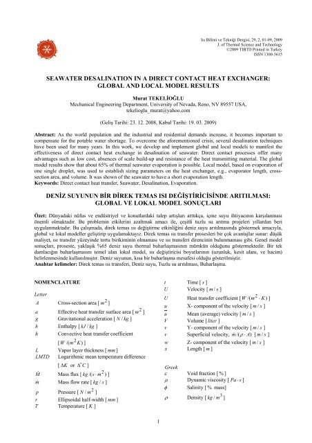
Isı Bilimi ve Tekniği Dergisi, 29, 2, 01-09, 2009J. of Thermal Science and Technology©2009 TIBTD Pr<strong>in</strong>ted <strong>in</strong> TurkeyISSN 1300-3615SEAWATER DESALINATION IN A DIRECT CONTACT HEAT EXCHANGER:GLOBAL AND LOCAL MODEL RESULTSMurat TEKELİOĞLUMechanical Eng<strong>in</strong>eer<strong>in</strong>g Department, University of Nevada, Reno, NV 89557 USA,tekelioglu_murat@yahoo.com(Geliş Tarihi: 23. 12. 2008, Kabul Tarihi: 19. 03. 2009)Abstract: As the world population and the <strong>in</strong>dustrial and residential demands <strong>in</strong>crease, it becomes important tocompensate for the potable water shortage. To overcome the aforementioned crisis, several <strong>desal<strong>in</strong>ation</strong> techniqueshave been used for many years. In this work, we develop and implement global and local models to manifest theeffectiveness of <strong>direct</strong> <strong>contact</strong> <strong>heat</strong> exchange <strong>in</strong> <strong>desal<strong>in</strong>ation</strong> of <strong>seawater</strong>. Direct <strong>contact</strong> processes offer manyadvantages such as low cost, absences of scale build-up and resistance of the <strong>heat</strong> transmitt<strong>in</strong>g material. The globalmodel results show that about 65% of thermal <strong>seawater</strong> evaporation is possible. Local model, based on evaporation ofone s<strong>in</strong>gle droplet, was used to establish siz<strong>in</strong>g parameters on the <strong>heat</strong> <strong>exchanger</strong>, e.g., evaporator length, crosssectionarea, and volume. It was shown of the <strong>seawater</strong> to have a short evaporation length.Keywords: Direct <strong>contact</strong> <strong>heat</strong> transfer, Seawater, Desal<strong>in</strong>ation, Evaporation.DENİZ SUYUNUN BİR DİREK TEMAS ISI DEĞİŞTİRİCİSİNDE ARITILMASI:GLOBAL VE LOKAL MODEL SONUÇLARIÖzet: Dünyadaki nüfus ve endüstriyel ve konutlardaki talep artışları arttıkça, içme suyu ihtiyacının karşılanmasıönemli olmaktadır. Bu problem<strong>in</strong> etkiler<strong>in</strong>i azaltmak amacı ile, çeşitli tuzlu su arıtma projeleri yıllardan beriuygulanmaktadır. Bu çalışmada, direk temas ısı değiştirme etk<strong>in</strong>liğ<strong>in</strong>i deniz suyu arıtılmasında göstermek amacıyla,global ve lokal modeller geliştirip uygulamaktayız. Direk temas ısı transfer prosesleri bir çok avantajlar sunar: düşükmaliyet, ısı transfer yüzey<strong>in</strong>de tortu birikim<strong>in</strong><strong>in</strong> olmaması ve ısı transferi direnc<strong>in</strong><strong>in</strong> bulunmaması gibi. Genel modelsonuçları, proseste, yaklaşık %65 deniz suyu thermal buharlaşmasının mümkün olduğunu göstermektedir. Bir tekdamlacığın buharlaşmasını temel alan lokal model, ısı değiştiricisi boyutlarının (uzunluk, kesit alanı, ve hacim)belirlenmes<strong>in</strong>de kullanılmıştır. Deniz suyunun, kısa bir buharlaşma mesafesi olduğu gösterilmiştir.Anahtar kelimeler: Direk temas ısı transferi, Deniz suyu, Tuzlu su arıtılması, Buharlaşma.NOMENCLATURELetter2A Cross-section area [ m ]2a Effective <strong>heat</strong> transfer surface area [ m ]g Gravitational acceleration [ N / kg ]h Enthalpy [ kJ / kg ]h Convective <strong>heat</strong> transfer coefficient[ W /( m2 K ) ]L Vapor layer thickness [ mm ]LMTD Logarithmic mean temperature difference[ Δ K or Δ o C ]M & Mass flux [ kg /( s ⋅ m2) ]m& Mass flow rate [ kg / s ]2p Pressure [ N / m ]r Ellipsoidal half-width [ mm ]T Temperature [ K ]t Time [ s ]U Velocity [ m / s ]U Heat transfer coefficient [ W /( m2 ⋅ K ) ]u X- component of the velocity [ m / s ]u Mean (average) velocity [ m / s ]V Volume [ liter ]v Y- component of the velocity [ m / s ]v Superficial velocity, m& /( ρ ⋅ A)[ m / s ]w Z- component of the velocity [ m / s ]x Length [ m ]Greekε Void fraction [ % ]μ Dynamic viscosity [ Pa ⋅ s ]φ Sal<strong>in</strong>ity [ % mass]ρ Density [ kg / m3]1
SubscriptatmbbccpAtmosphericBr<strong>in</strong>eBeneathCont<strong>in</strong>uous phaseCombustion productsC 3H 8 PropaneCO 2 Carbon dioxided Dispersed phasee Evaporatorf LiquidfgLiquid-to-gasH 2O(g)Water vapor (combustion products)m Mean (average)N 2 Nitrogeno Outero Initialp Productsp Constant pressureR References Surfaces Saturatedsw Seawatert, wv Total water vaporv Vaporv Volumetricwv Water vaporINTRODUCTIONIn contrast to the ris<strong>in</strong>g problem of potable watershortage, most of the world surface is covered by water.However, the world’s 94% of available water is saltyand only 6% is fresh (International Desal<strong>in</strong>ationAssociation (IDA), 2000). Further, 72% of the latter isunderground and 27% is <strong>in</strong> glaciers. Therefore, to solvethe problem of potable quality water shortage, it issuitable to implement <strong>desal<strong>in</strong>ation</strong> methods to turn thesal<strong>in</strong>e water <strong>in</strong>to a potable water source. This processalso benefits the agriculture.Installed capacity of the <strong>desal<strong>in</strong>ation</strong> plants, from mostto-the-least,were given as multi-stage flash<strong>in</strong>g (44%),reverse osmosis (42%), electro dialysis (6%), multieffectdistillation (4%), and vapor-compression (4%)(IDA, 2000). It was noted that the total productioncapacity of the multi-stage flash<strong>in</strong>g (MSF) and reverseosmosis (RO) systems were competitive with9.8 ⋅ 106m3/ day versus 9.6 ⋅ 106m3/ day as of 1997.A research overview on the processes of MSF and ROsystems was presented (Khawaji et al., 2008). Thermaland membrane systems and other alternative methodswere discussed under the economics of such plants. Thefoul<strong>in</strong>g of membrane <strong>in</strong> membrane distillation (MD)systems was studied (Hsu et al., 2002). The aim was todistill the raw <strong>seawater</strong>, a NaCl solution, and a pre-treatwater <strong>in</strong> MD and compare the permeate fluxes( kg /( m2 h ) ) with presence of foul<strong>in</strong>g at the membranesurface. They observed with the raw <strong>seawater</strong>, nearlyhalf permeate flux (more foul<strong>in</strong>g) compared to NaClsolution. They applied ultrasound clean<strong>in</strong>g technique tothe membrane to overcome the foul<strong>in</strong>g. A similar MDprocess was <strong>in</strong>vestigated (Termpiyakul et al., 2005). Amembrane distillation coefficient ( C , kg /( m2⋅ h ⋅ Pa))was found on pure water and the other C values wereestimated for high salt concentrations (up to 35,000mg / L ). In the other study, theoretical and experimentalvalues of condensation and evaporation coefficientswere <strong>in</strong>cluded (Marek and Straub, 2001). They po<strong>in</strong>tedout the real gas effects <strong>in</strong> the processes and found thatthe condensation coefficient for water was greater thanits evaporation coefficient. A theoretical model for theevaporation of dispersed volatile drops <strong>in</strong> <strong>direct</strong> <strong>contact</strong>of a cont<strong>in</strong>uous immiscible liquid was described(Kendoush, 2004). The author developed <strong>heat</strong> transfercoefficients for n-pentane and n-butane coolant drops.Direct <strong>contact</strong> MD was given (Yun et al., 2006) forhigh-concentration NaCl solutions from theoretical andexperimental aspects.In this paper, we <strong>in</strong>vestigate the effectiveness of <strong>direct</strong><strong>contact</strong> <strong>heat</strong> exchange process <strong>in</strong> <strong>seawater</strong> <strong>desal<strong>in</strong>ation</strong>.A spray- column was used. With two types of fuels(Hydrogen and Propane) tested on two models (globaland local), the outcomes aimed to determ<strong>in</strong>e the amountof water vapor out of <strong>seawater</strong> evaporation andevaporator dimensions such as length, cross-sectionarea, and volumeGLOBAL MODELA schematic <strong>direct</strong>-<strong>contact</strong> <strong>heat</strong>-<strong>exchanger</strong> (DCHX) isshown <strong>in</strong> Fig. 1. The combustion products enter <strong>in</strong> thespray-column and rise toward the fall<strong>in</strong>g-off <strong>seawater</strong>droplets from a spr<strong>in</strong>kler system and give their <strong>heat</strong> tothe <strong>seawater</strong>. The evaporated <strong>seawater</strong> (water vapor) isreceived from the top and the much denser br<strong>in</strong>e (<strong>in</strong> saltcontent) is delivered from the bottom of the system. Thesensible cool<strong>in</strong>g of the combustion products is the onsetfor the <strong>seawater</strong> mass transfer (latent <strong>heat</strong>). The watervapor received from the top of the <strong>heat</strong> <strong>exchanger</strong> iscondensed <strong>in</strong> a condenser. A pre-<strong>heat</strong>er can also replacethe condenser, which pre<strong>heat</strong>s, e.g., the <strong>in</strong>com<strong>in</strong>g<strong>seawater</strong> up to its temperature of saturation.Apply<strong>in</strong>g the first law of thermodynamics to the systemshown <strong>in</strong> Fig. 1, we getm & swhsw+ m&cphcp= m&php + m&bhb(1)where m& sw is the <strong>seawater</strong> mass flow rate ( kg / s ),h sw is the <strong>seawater</strong> enthalpy ( kJ / kg ), m& cp is themass flow rate of the combustion products ( kg / s ),h cp is the enthalpy of the combustion products2
( kJ / kg ), m& p is the mass flow rate of the products( kg / s ), h p is the enthalpy of the products ( kJ / kg ),m& b is the br<strong>in</strong>e mass flow rate ( kg / s ), and h b is thebr<strong>in</strong>e enthalpy ( kJ / kg ). The two mass balanceequations givem & sw + m&cp = m&b + m&p(2)Seawater.m swEvaporatorBr<strong>in</strong>e.m bProducts .m pCombustionproducts.m cpFigure 1. Schematic of the <strong>direct</strong> <strong>contact</strong> <strong>heat</strong> <strong>exchanger</strong> with<strong>in</strong>put and output.where m& p , m & p = m&cp + m&wv is comprised of the bothcombustion products and water vapor of <strong>seawater</strong>evaporationm & sw = m&b + m&wv(3)The salt concentration balance equationφ* sw m & sw = φ b m&b + φ p m&p(4)where φ sw , φ b , and φ p are the <strong>seawater</strong>, br<strong>in</strong>e, andproducts sal<strong>in</strong>ities, respectively, and m& * p is taken asH 2O(g)(sum of the water vapor of products ofcombustion, m & H 2O(g),cp and <strong>seawater</strong> evaporation,m& wv ). We solved Eqs. (1)-(4) for m& sw , m& wv , m& p ,and m& b , then calculated m & t, wv = m&wv + m&H 2O(g),cp .In the calculations, φ sw = 3.53%, φ b =10%,φ p = 0.025% , h sw = 405.8kJ/ kg , h b = 381kJ/ kg ,h cp (at T cp = 1197K, T cp = 1263K, T cp = 423K)were used and m& cp values were estimatedexperimentally from the combustion of C 3H8with air.As the fuel mass flow rates were relatively small <strong>in</strong> ourprelim<strong>in</strong>ary experiments, m& C3H8values were taken 10times as greater of those, or as−32.1⋅ 10 , 3.0⋅10−3kg / s−30.3⋅ 10 ,−31.2⋅ 10 ,Figures 2 and 3 show m& wv and m & t , wv changes withm& cp of C 3H8and H 2 fuels. m& cp ’s were calculated,respectively, for the C3H8-air combustion and H 2 -aircombustion with no dissociation or association <strong>in</strong> theproducts fromm & cp = m&CO2 + m&H 2O(g)+ m&N 2(5)m & cp = m&H 2O(g)+ m&N 2(6)where the right hand side represents the products gasesout of combustionsWater vapor (10 -3 kg/s)6005004003002001000WV, Tcp = 1197 K (Propane-Air)TWV, Tcp = 1197 KWV, Tcp = 1263 K (Hydrogen-Air)TWV, Tcp = 1263 KWV, Tcp = 423 K (Hydrogen-Air)TWV, Tcp = 423 K0 0.5 1 1.5 2 2.5 3 3.5Hydrogen or Propane mass flow rate (10 -3 kg/s)Figure 2. Water vapor mass flow rate with fuels mass flowrate (equal mass flow rate).Water vapor (10 -3 kg/s)2520151050WV, Tcp = 1263 K (Hydrogen-Air)TWV, Tcp = 1263 K0 0.02 0.04 0.06 0.08 0.1 0.12 0.14 0.16Hydrogen mass flow rate (10 -3 kg/s)Figure 3. Water vapor mass flow rate with Hydrogen massflow rate (equal mole flow rate).LOCAL MODELIn order to assess siz<strong>in</strong>g parameters on the evaporator, alocal evaporation model was used, which assumed100% droplet evaporation (thus, m&b = 0g/ s , andm & sw = m&wv ). Fig. 4 shows the ellipsoidal droplet used3
<strong>in</strong> the current model.r o = 250μm.r o= 250μmand t e was given forL2dpu = −(11)12μ v dxIn the column, the dispersed phase denotes the <strong>seawater</strong>and the cont<strong>in</strong>uous phase denotes the combustionproducts. The model we used here<strong>in</strong> was similar to theone earlier given by (Elshaik, 1990) except <strong>in</strong> that thedroplet shape we considered was ellipsoidal.Consider<strong>in</strong>g the simplify<strong>in</strong>g assumptions <strong>in</strong> Cartesian(x, y, z-) coord<strong>in</strong>ates∂uv ≅ 0 , w ≅ 0 , ≅ 0∂x(7)Navier-Stokes equations <strong>in</strong> x-<strong>direct</strong>ion (on layer L ) canbe given as2dp d u0 = − + μ v(8)dx 2dywhere μ v is the dispersed phase (<strong>seawater</strong>) vapordynamic viscosity ( Pa ⋅ s ). We assumed lam<strong>in</strong>ar flowregime <strong>in</strong>side the layer and μ v was taken as constant.Integrat<strong>in</strong>g this equation under boundary conditionsu ( 0) = 0 and u ( L)= 0 , we gety dpu = ( y − L)(9)2 μ v dxEvaporation mass flow rate on the r<strong>in</strong>g element <strong>in</strong> Fig. 4can be written asu(2πxL)ρ M ( x2v = & π )(12)where M & is the mass flux ( kg /( s ⋅ m2) ), ρ v is the3dispersed phase density ( kg / m ). After comb<strong>in</strong><strong>in</strong>g thelast two equationsdp 6μMx= −v&(13)dx 3ρvLand tak<strong>in</strong>g the <strong>in</strong>tegration forflow, u = 0 ), we getx = r , p = 0 (no vapor3μ v M 2 2p(x)=& ( r − x )(14)3ρvLwhere r = r(t)and 0 ≤ x ≤ r <strong>in</strong> the course ofevaporation. Writ<strong>in</strong>g a force balance on the droplettak<strong>in</strong>g <strong>in</strong>to account its weightr( ρ l − ρv) Vg =∫p(2πx)dx(15)0Substitut<strong>in</strong>g p (x), we f<strong>in</strong>drroH3 μ M&( ρ gvl − ρv) = r(16)8 3ρvLyLFigure 4. Ellipsoidal droplet and vapor layer on the r<strong>in</strong>gelement beneath, r = r(t), L = L(t), and H = 3ro. The thirddimension is also r = r(t)and r oThe mean velocity for the water vapor isL1u =∫udyL0with Eq. (9)x(10)where ρ l is the dispersed phase liquid density( kg / m3), g is the gravitational acceleration( g = 9.81N/ kg ), r ( = r(t)) is the mean droplet width4π( m ), and V 3r33= is the droplet volume ( m ). Rate3of evaporation was given on s<strong>in</strong>gle droplet asdV 2ρl= −πrM&(17)dtPlugg<strong>in</strong>gr4π3V = 3rand <strong>in</strong>tegrat<strong>in</strong>g between r o and3M&r = ro− t(18)12ρl4
which gives the decay of r o dur<strong>in</strong>g evaporation. Inaddition, <strong>heat</strong> given to the droplets by the combustionproductsQ & = hcAs( Tcp−Ts)(19)and the required <strong>heat</strong> for the droplets evaporation isQ & = MA &b h fg(20)<strong>in</strong> which h c is the convective <strong>heat</strong> transfer coefficientfor the combustion products ( W /( m2 K ) ), A s is thesurface area of the ellipsoidal droplet from the KnudThomsen formula ( p = 1. 6075 , with a relative error ≤1.061%) ( m2), T cp is the combustion productstemperature ( K ), T s is the saturation temperature forthe dispersed phase at p = 101. 325kPa( T s = 373.15K+ BPR(0.28K)) where BPR is the<strong>seawater</strong> boil<strong>in</strong>g po<strong>in</strong>t rise (Billet, 1989; Wark, 1995),2A b is the area beneath the <strong>seawater</strong> droplet ( m ), andh fg is the latent <strong>heat</strong> of vaporization for the dispersedphase ( kJ / kg ). Equat<strong>in</strong>g last two equations0.622⎛ 2 31.60751⎞4h⎜ ⋅ + ⎟c( Tcp− Ts)⎜ 3 ⎟M& =⎝⎠(21)h fgand substitut<strong>in</strong>g <strong>in</strong>to Eq. (18), we f<strong>in</strong>d0.622⎛ 2 31.60751⎞h ⎜ ⋅ + ⎟c( Tcp− Ts)⎜ 3 ⎟r = r⎠o −⎝t (22)3ρlh fgIn order to determ<strong>in</strong>e the decay of droplet volume, wesubstitute Eqs. (21) and (22) <strong>in</strong>to Eq. (17) and <strong>in</strong>tegratebetween V ( 0) = Voand V ( t)= V to get0.622⎛ ⎞⎜ 2⋅31.6075+ 14π h⎟c( T −⎜⎟ cp Ts)3⎝⎠V −Vo= −×ρlh fgt ⎛⎜ hc∫ ⎜ro−⎜ 3ρlh fg0 ⎝20.622⎛ 1.6075 ⎞⎞⎜ 2⋅3+ 1⎟( Tcp−Ts) t dt⎜ 3 ⎟⎟ ⎟⎟ ⎝⎠⎠(23)Evaporation times calculated via Eqs. (22) and (23)were identical. The <strong>seawater</strong> mass flow rate wascalculated due to the sensible cool<strong>in</strong>g of the combustionproductsm & swc p, cp ( Tcp− Ts)=m&cp h fg(24)where c p , cp is the specific <strong>heat</strong> for the combustionproducts ( kJ /(kgK)): c p , cp was evaluated at1Δ T m = ( Tcp+ Ts) and m& cp s were calculated as <strong>in</strong>2Eqs. (5) and (6) with no dissociation or association <strong>in</strong>reactionsThe cross-section area of the evaporator was givenbased on the properties of the combustion productsm&cpAe=ρcp( 1−ε d ) vcp(25)where ρ cp is the density of the combustion products( kg / m3), v cp is the velocity of the combustionproducts ( m / s), and ε d is the void fraction def<strong>in</strong>ed asthe ratio of the volume of dispersed phase to that of totalevaporator volume (-). Tak<strong>in</strong>g <strong>in</strong>to account the fact thatthe evaporator is occupied by the dispersed andcont<strong>in</strong>uous phases throughout1ε d =ρ swm&cp1+ρcpm&swwithρ f + ρvρ sw = ,2(26)pρ =atmcp(27)⎛ T + ⎞⎜cp TsRcp⎟⎝ 2 ⎠In order to f<strong>in</strong>d the evaporation length,Δ xeΔ x e = U Rte(28)wherevdvUcR = −ε d 1− ε d(29)and vd= m&sw /( ρswAe) and vc= m&cp /( ρcpAe)<strong>in</strong>side the evaporator column. Hence, through Eqs. (25)and (28), the evaporator volume was estimatedVe≅ AeΔxe(30)5
Lastly, the volumetric <strong>heat</strong> transfer coefficient ( U v )was calculated fromUa m&swhfgU v = =VeVe⋅ LMTDor,(31)m& swhfg = U vVe⋅ LMTD(32)2a be<strong>in</strong>g the effective <strong>heat</strong> transfer surface area ( m )and U ≅ hc. The fact ( U ≅ hc) is due to the twofactors: First is the absence of the <strong>heat</strong> transferresistance of the <strong>heat</strong> transmitt<strong>in</strong>g material and secondis the negligible <strong>heat</strong> transfer resistance of the dispersedphase compared to the combustion products (Kreith andBoehm, 1988). Logarithmic mean temperaturedifference ( LMTD ) was def<strong>in</strong>ed as( Tcp− Tsw)− ( Tp− Tsw)LMTD =(33)Tcp− TswlnTp− TswIn us<strong>in</strong>g LMTD , the products were assumed to exit theevaporator as super<strong>heat</strong>ed at T p = 375KWater vapor (10 -3 kg/s)9080706050403020100WV, Tcp = 1197 K (Propane-Air)TWV, Tcp = 1197 KWV, Tcp = 1263 K (Hydrogen-Air)TWV, Tcp = 1263 KWV, Tcp = 423 K (Hydrogen-Air)TWV, Tcp = 423 K0.0 0.5 1.0 1.5 2.0 2.5 3.0 3.5Hydrogen or Propane mass flow rate (10 -3 kg/s)Figure 5. Water vapor mass flow rate with fuels mass flowrate (equal mass flow rate).We present local model resultsm& wv , m & t , wv , A e , t e ,Δ x e , and V e <strong>in</strong> Figs. (5)- (16). In Figs. (5) and (6),m& wv and m & t , wv <strong>in</strong>crease with m& H 2 or m& C3H8due tothe total enthalpy carried away by the combustionproducts, or m& cp . The effect of void fraction ( ε d ) onthe cross- section area of the evaporator is shown <strong>in</strong> Fig.(7). ε d values were less than 0.1% for the Propane-aircombustion ( T cp = 1197K), Hydrogen-air combustion( T cp = 1263K), and Hydrogen-air combustion( T cp = 1263K, equal mole flow rate) and less than0.01% for the Hydrogen-air combustion ( T cp = 423K).These results <strong>in</strong>dicate that <strong>in</strong>deed the dispersed phaseoccupies only a small fraction of the total evaporatorvolume.In Figs. (8)-(11),values was nearly the same forΔ xewas seen to decrease with h c ; t eT cp = 1197KandT cp = 1263K which substantially differed forT cp = 423K (See Fig. 12). As h c <strong>in</strong>creased, V e wasseen to decrease. This was shown <strong>in</strong> Figs. (13)-(16).Results <strong>in</strong> Figs. (8)- (16) were <strong>in</strong>cluded for uniform(constant) h c values. In the course of evaporation, h cchanges were reported for a bubble column design(Kendoush, 2004) and the references there<strong>in</strong>.Water vapor (10 -3 kg/s)4.543.532.521.510.50WV, Tcp = 1263 K (Hydrogen-Air)TWV, Tcp = 1263 K0 0.02 0.04 0.06 0.08 0.1 0.12 0.14 0.16Hydrogen mass flow rate (10 -3 kg/s)Figure 6. Water vapor mass flow rate with fuel mass flow rate(equal mole flow rate).Ae (m 2 )7.06.05.04.03.02.01.00.0Propane-Air (Tcp = 1197 K)Hydrogen-Air (Tcp = 1263 K)Hydrogen-Air (Tcp = 423 K)Hydrogen-Air (Tcp = 1263 K) Eq Mole0 0.5 1 1.5 2 2.5 3 3.5Hydrogen or Propane mass flow rate (10 -3 kg/s)Figure 7. Evaporator cross-section area versus fuels massflow rate.Larger values for m& wv <strong>in</strong> Figs. (2) and (3) versus Figs.(5) and (6) was due to the properties of the combustionproducts evaluated at T cp (global model) versus T m(local model). Heat of vaporization ( h fg ) values<strong>direct</strong>ly plugged <strong>in</strong>to the local model resulted <strong>in</strong> smallvalues for m& wv6
Δx e (10 -2 m)2.01.81.61.41.21.00.80.60.40.20.0Propane: 0.3/(1000) kg/sPropane: 1.2/(1000) kg/sPropane: 2.1/(1000) kg/sPropane: 3.0/(1000) kg/s0 1000 2000 3000 4000 5000 6000h c (W/(m 2 K))Figure 8. Evaporation length versus <strong>heat</strong> transfer coefficient,Propane-air combustion ( T cp = 1197K).Δxe (10 -2 m)2.01.81.61.41.21.00.80.60.40.20.0Hydrogen: 0.014/(1000) kg/sHydrogen: 0.055/(1000) kg/sHydrogen: 0.096/(1000) kg/sHydrogen: 0.137/(1000) kg/s0 1000 2000 3000 4000 5000 6000h c (W/(m 2 K))Figure 11. Evaporation length versus <strong>heat</strong> transfer coefficient,Hydrogen-air combustion, equal mole flow rate withT cp = 1263K .Δx e (10 -2 m)2.01.81.61.41.21.00.80.60.40.20.0Hydrogen: 0.3/(1000) kg/sHydrogen: 1.2/(1000) kg/sHydrogen: 2.1/(1000) kg/sHydrogen: 3.0/(1000) kg/s0 1000 2000 3000 4000 5000 6000h c (W/(m 2 K))Figure 9. Evaporation length versus <strong>heat</strong> transfer coefficient,Hydrogen-air combustion ( T cp = 1263K).Δx e (10 -2 m)35302520151050Hydrogen: 0.3/(1000) kg/sHydrogen: 1.2/(1000) kg/sHydrogen: 2.1/(1000) kg/sHydrogen: 3.0/(1000) kg/s0 1000 2000 3000 4000 5000 6000h c (W/(m 2 K))Figure 10. Evaporation length versus <strong>heat</strong> transfer coefficient,Hydrogen-air combustion ( T cp = 423K).te (s)302520151050Propane-Air (Tcp = 1197 K)Hydrogen-Air (Tcp = 1263 K)Hydrogen-Air (Tcp = 423 K)Hydrogen-Air (Tcp = 1263 K) Eq Mole0 1000 2000 3000 4000 5000 6000h c (W/(m 2 K))Figure 12. Evaporation time versus <strong>heat</strong> transfer coefficientfor the fuels.Ve (liter)454035302520151050Propane: 0.3/(1000) kg/sPropane: 1.2/(1000) kg/sPropane: 2.1/(1000) kg/sPropane: 3.0/(1000) kg/s0 1000 2000 3000 4000 5000 6000h c (W/(m 2 K))Figure 13. Evaporator volume versus <strong>heat</strong> transfer coefficientfor Propane-air combustion ( T cp = 1197K).7
V e (liter)120100806040Hydrogen: 0.3/(1000) kg/sHydrogen: 1.2/(1000) kg/sHydrogen: 2.1/(1000) kg/sHydrogen: 3.0/(1000) kg/swas focused on. The spray-column evaporation showsunique fluid dynamics characteristics compared to abubble column design and the process <strong>in</strong>side the presentspray-column somewhat resembles a swamp cooler.From our global model center<strong>in</strong>g on first law ofthermodynamics, we showed that about 65% of the<strong>in</strong>com<strong>in</strong>g <strong>seawater</strong> evaporation was possible. Thisdef<strong>in</strong>ed the recovery ratio ( m & wv / m&sw ) of the <strong>seawater</strong>evaporation process.2000 1000 2000 3000 4000 5000 6000h c (W/(m 2 K))Figure 14. Evaporator volume versus <strong>heat</strong> transfer coefficientfor Hydrogen-air combustion ( T cp = 1263K).V e (liter)10008006004002000Hydrogen: 0.3/(1000) kg/sHydrogen: 1.2/(1000) kg/sHydrogen: 2.1/(1000) kg/sHydrogen: 3.0/(1000) kg/s0 1000 2000 3000 4000 5000 6000h c (W/(m 2 K))Figure 15. Evaporator volume versus <strong>heat</strong> transfer coefficientfor Hydrogen-air combustion ( T cp = 423K).V e (liter)5.04.54.03.53.02.52.01.51.00.50.0Hydrogen: 0.014/(1000) kg/sHydrogen: 0.055/(1000) kg/sHydrogen: 0.096/(1000) kg/sHydrogen: 0.137/(1000) kg/s0 1000 2000 3000 4000 5000 6000h c (W/(m 2 K))Figure 16. Evaporator volume versus <strong>heat</strong> transfer coefficientfor Hydrogen-air combustion, equal mole flow rate withT cp = 1263K .CONCLUSIONSWe developed two <strong>heat</strong> transfer models and evaluatedthe effectiveness of a <strong>direct</strong>-<strong>contact</strong> <strong>heat</strong> exchangeprocess <strong>in</strong> <strong>desal<strong>in</strong>ation</strong> of <strong>seawater</strong>. A spray- columnLocal model center<strong>in</strong>g on Navier- Stokes Eqs. was usedto estimate the siz<strong>in</strong>g on the <strong>heat</strong> <strong>exchanger</strong> <strong>in</strong>clud<strong>in</strong>gevaporator length, cross-section area, and volume. Itwas found that for a given enthalpy of the combustionproducts, only certa<strong>in</strong> amount of <strong>seawater</strong> canevaporate, thereby, be desal<strong>in</strong>ated. Increas<strong>in</strong>g T cp wasfound to turn out lower Δ xe, t e , and V e but <strong>in</strong>creasem& sw , m& wv , and U v .The other similar methods of thermal distillation, withlower yields compared to MSF and RO processes,<strong>in</strong>clude distillation via freez<strong>in</strong>g and solar humidificationAn efficient <strong>direct</strong>- <strong>contact</strong> <strong>heat</strong> transfer process wasproposed <strong>in</strong> <strong>desal<strong>in</strong>ation</strong> of <strong>seawater</strong>. Experimentaltest<strong>in</strong>g is crucial to validate the process, which may<strong>in</strong>itially substitute a cheaper fuel, e.g., a hydrocarbon.ACKNOWLEDGEMENTSThe author thanks to Dr. Byard D. Wood through theU.S. Bureau of Reclamation and U.S. Department ofEnergy for their support on this project.REFERENCESBillet, R., Evaporation Technology, VCH Publishers,New York, 1989.Elshaik N. M., Direct Contact Heat Transfer to aDispersed Droplet with Change of Phase, NorthCarol<strong>in</strong>a State University, Dissertation thesis, 1990.Hsu, S. T., Cheng, K. T., and Chiou, J. S., SeawaterDesal<strong>in</strong>ation by Direct Contact Membrane Distillation,Desal<strong>in</strong>ation 143, 279-287, 2002.International Desal<strong>in</strong>ation Association (IDA), 2000.Available at http://www.idadesal.org/Kendoush, A. A., Theory of Convective DropEvaporation <strong>in</strong> Direct Contact with an ImmiscibleLiquid, Desal<strong>in</strong>ation 169, 33–41, 2004.Khawaji, A. D., Kutubkhanah, I. K., and Wie, J-M.,Advances <strong>in</strong> Seawater Desal<strong>in</strong>ation Technologies,Desal<strong>in</strong>ation 221, 47–69, 2008.Kreith, F. and Boehm, R. F., Direct Contact HeatTransfer, Hemisphere Pub Corp, Wash<strong>in</strong>gton, 1988.8
Marek, R. and Straub, J., Analysis of the EvaporationCoefficient and the Condensation Coefficient of Water,Int. J. of Heat and Mass Transfer 44, 39-53, 2001.Termpiyakul, P., Jiraratananon, R., and Srisurichan, S.,Heat and Mass Transfer Characteristics of a DirectContact Membrane Distillation Process forDesal<strong>in</strong>ation, Desal<strong>in</strong>ation 177, 133-141, 2005.Yun, Y., Ma, R., Zhang, W., Fane, A. G., and Li, J.,Direct Contact Membrane Distillation Mechanism forHigh Concentration NaCl Solutions, Desal<strong>in</strong>ation 188,251-262, 2006.Wark, K., Advanced Thermodynamics for Eng<strong>in</strong>eers,McGraw-Hill, New York, 1995.Murat TEKELİOĞLU received his B.Sc. degree <strong>in</strong> Mechanical Eng<strong>in</strong>eer<strong>in</strong>g from theIstanbul Technical University <strong>in</strong> 1998. He holds M.Sc. and Ph.D. degrees <strong>in</strong> MechanicalEng<strong>in</strong>eer<strong>in</strong>g from the University of Nevada, Reno, earned <strong>in</strong> 2000 and 2005, respectively.His research <strong>in</strong>terests <strong>in</strong>clude thermal, electrical, and optical systems design andsimulation. He is an Assistant Professor of Mechanical Eng<strong>in</strong>eer<strong>in</strong>g Department <strong>in</strong>Karabük University and currently teach<strong>in</strong>g at Gazi University <strong>in</strong> Ankara.9


