Rugged Operating System (ROS ® ) Software User ... - RuggedCom
Rugged Operating System (ROS ® ) Software User ... - RuggedCom
Rugged Operating System (ROS ® ) Software User ... - RuggedCom
- No tags were found...

Create successful ePaper yourself
Turn your PDF publications into a flip-book with our unique Google optimized e-Paper software.
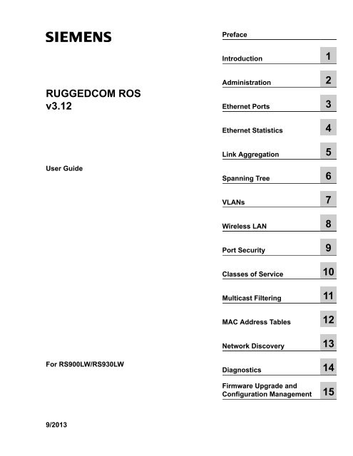
PrefaceIntroduction 1RUGGEDCOM <strong>ROS</strong>v3.12Administration 2Ethernet Ports 3Ethernet Statistics 4Link Aggregation 5<strong>User</strong> GuideSpanning Tree 6VLANs 7Wireless LAN 8Port Security 9Classes of Service 10Multicast Filtering 11MAC Address Tables 12Network Discovery 13For RS900LW/RS930LWDiagnostics 14Firmware Upgrade andConfiguration Management 159/2013
RUGGEDCOM <strong>ROS</strong><strong>User</strong> GuideTable of Contents2.7 IP Services ................................................................................................................................ 432.8 Data Storage ............................................................................................................................. 452.9 <strong>System</strong> Identification .................................................................................................................. 462.10 Passwords ............................................................................................................................... 462.11 <strong>System</strong> Time Management ........................................................................................................ 492.11.1 Configuring Time and Date ............................................................................................. 492.11.2 Configuring NTP Service ................................................................................................ 512.12 SNMP Management ................................................................................................................. 522.12.1 SNMP <strong>User</strong>s ................................................................................................................. 522.12.2 SNMP Security to Group Maps ....................................................................................... 542.12.3 SNMP Access ............................................................................................................... 552.13 RADIUS ................................................................................................................................... 562.13.1 RADIUS overview .......................................................................................................... 572.13.2 <strong>User</strong> Login Authentication and Authorization .................................................................... 572.13.3 802.1X Authentication .................................................................................................... 582.13.4 RADIUS Server Configuration ......................................................................................... 592.14 TACACS+ ................................................................................................................................ 602.14.1 <strong>User</strong> Login Authentication and Authorization .................................................................... 602.14.2 TACACS+ Server Configuration ...................................................................................... 602.14.3 <strong>User</strong> Privilege Level Configuration .................................................................................. 612.14.4 TACACS+ Server Privilege Configuration ........................................................................ 622.15 DHCP Relay Agent .................................................................................................................. 622.16 Syslog ..................................................................................................................................... 632.16.1 Configuring Local Syslog ................................................................................................ 642.16.2 Configuring Remote Syslog Client .................................................................................. 652.16.3 Configuring the Remote Syslog Server ............................................................................ 652.17 Troubleshooting ........................................................................................................................ 66Chapter 3Ethernet Ports .................................................................................................... 693.1 Controller Protection Through Link-Fault-Indication (LFI) ............................................................... 693.2 SFP Transceiver Support (if applicable) ....................................................................................... 713.2.1 Configuring an SFP Port .................................................................................................. 713.2.2 Monitoring an SFP Port ................................................................................................... 713.2.3 Displaying Information for an SFP Transceiver .................................................................. 723.3 Ethernet Ports Configuration and Status ...................................................................................... 733.3.1 Port Parameters .............................................................................................................. 733.3.2 Port Rate Limiting ............................................................................................................ 763.3.3 Port Mirroring .................................................................................................................. 773.3.3.1 Port Mirroring Limitations ....................................................................................... 783.3.4 Cable Diagnostics ............................................................................................................ 78v
Table of ContentsRUGGEDCOM <strong>ROS</strong><strong>User</strong> Guide3.3.4.1 Running Cable Diagnostics ................................................................................... 803.3.4.2 Interpreting Cable Diagnostics Results ................................................................... 813.3.4.3 Calibrating Estimated Distance To Fault ................................................................. 813.3.5 Link Detection Options ..................................................................................................... 823.3.6 EoVDSL Parameters (when applicable) ............................................................................ 833.3.7 Port Status ...................................................................................................................... 853.3.8 Resetting Ports ................................................................................................................ 863.4 Troubleshooting .......................................................................................................................... 86Chapter 4Ethernet Statistics .............................................................................................. 874.1 Viewing Ethernet Statistics .......................................................................................................... 874.2 Viewing Ethernet Port Statistics .................................................................................................. 894.3 Clearing Ethernet Port Statistics .................................................................................................. 934.4 Remote Monitoring (RMON) ........................................................................................................ 934.4.1 RMON History Controls ................................................................................................... 934.4.2 RMON History Samples ................................................................................................... 954.4.3 RMON Alarms ................................................................................................................. 974.5 RMON Events .......................................................................................................................... 1014.6 RMON Event Log ..................................................................................................................... 1024.7 List of Objects Eligible for RMON Alarms ................................................................................... 104Chapter 5Link Aggregation .............................................................................................. 1095.1 Link Aggregation Operation ....................................................................................................... 1095.1.1 Link Aggregation Rules .................................................................................................. 1105.1.2 Link Aggregation Limitations ........................................................................................... 1115.2 Link Aggregation Configuration .................................................................................................. 1125.2.1 Configuring Port Trunks ................................................................................................. 113Chapter 6Spanning Tree .................................................................................................. 1156.1 RSTP Operation ....................................................................................................................... 1156.1.1 RSTP States and Roles ................................................................................................. 1166.1.2 Edge Ports .................................................................................................................... 1186.1.3 Point-to-Point and Multipoint Links .................................................................................. 1186.1.4 Path and Port Costs ...................................................................................................... 1186.1.5 Bridge Diameter ............................................................................................................ 1196.1.6 Fast Root Failover ......................................................................................................... 1196.2 MSTP Operation ...................................................................................................................... 1206.2.1 MST Regions and Interoperability ................................................................................... 121vi
RUGGEDCOM <strong>ROS</strong><strong>User</strong> GuideTable of Contents6.2.2 MSTP Bridge and Port Roles ......................................................................................... 1226.2.2.1 Bridge Roles: ...................................................................................................... 1226.2.2.2 Port Roles: ......................................................................................................... 1226.2.3 Benefits of MSTP .......................................................................................................... 1236.2.4 Implementing MSTP on a Bridged Network ..................................................................... 1246.3 RSTP Applications .................................................................................................................... 1246.3.1 RSTP in Structured Wiring Configurations ....................................................................... 1246.3.2 RSTP in Ring Backbone Configurations .......................................................................... 1266.3.3 RSTP Port Redundancy ................................................................................................. 1276.4 Spanning Tree Configuration ..................................................................................................... 1276.4.1 Bridge RSTP Parameters ............................................................................................... 1286.4.2 Port RSTP Parameters .................................................................................................. 1306.4.3 eRSTP Parameters ........................................................................................................ 1326.4.4 MST Region Identifier .................................................................................................... 1356.4.5 Bridge MSTI Parameters ................................................................................................ 1366.4.6 Port MSTI Parameters ................................................................................................... 1376.5 Spanning Tree Statistics ........................................................................................................... 1396.5.1 Bridge RSTP Statistics ................................................................................................... 1396.5.2 Port RSTP Statistics ...................................................................................................... 1416.5.3 Bridge MSTI Statistics .................................................................................................... 1436.5.4 Port MSTI Statistics ....................................................................................................... 1446.5.5 Clear STP Statistics ....................................................................................................... 1466.6 Troubleshooting ........................................................................................................................ 146Chapter 7VLANs ............................................................................................................... 1497.1 VLAN Operation ....................................................................................................................... 1497.1.1 VLANs and Tags ........................................................................................................... 1497.1.2 Tagged vs. Untagged Frames ......................................................................................... 1497.1.3 Native VLAN ................................................................................................................. 1507.1.4 Management VLAN ........................................................................................................ 1507.1.5 Edge and Trunk Port Types ............................................................................................ 1507.1.6 VLAN Ingress and Egress Rules .................................................................................... 1517.1.7 Forbidden Ports List ....................................................................................................... 1517.1.8 VLAN-aware And VLAN-unaware Modes Of Operation ..................................................... 1517.1.9 GVRP (GARP VLAN Registration Protocol) ..................................................................... 1527.1.10 PVLAN Edge ............................................................................................................... 1537.1.11 QinQ ........................................................................................................................... 1547.2 VLAN Applications .................................................................................................................... 1557.2.1 Traffic Domain Isolation .................................................................................................. 1557.2.2 Administrative Convenience ........................................................................................... 156vii
Table of ContentsRUGGEDCOM <strong>ROS</strong><strong>User</strong> Guide7.2.3 Reduced Hardware ........................................................................................................ 1567.3 VLAN Configuration .................................................................................................................. 1577.3.1 Global VLAN Parameters ............................................................................................... 1587.3.2 Static VLANs ................................................................................................................. 1587.3.3 Port VLAN Parameters ................................................................................................... 1607.3.4 VLAN Summary ............................................................................................................. 1617.4 Troubleshooting ........................................................................................................................ 162Chapter 8Wireless LAN .................................................................................................... 1658.1 WLAN Operation ...................................................................................................................... 1658.1.1 Wireless Extensions for Client/Bridge Operation .............................................................. 1668.1.2 Wireless Client/IP Bridge Operation ................................................................................ 1678.2 WLAN Configuration ................................................................................................................. 1688.2.1 Addressing Parameters .................................................................................................. 1708.2.2 Network Parameters ...................................................................................................... 1718.2.3 Security Parameters ...................................................................................................... 1738.2.4 MAC Filtering ................................................................................................................ 1758.2.5 RADIUS Parameters ...................................................................................................... 1768.2.6 Advanced Parameters .................................................................................................... 1778.2.7 WLAN DHCP Server ...................................................................................................... 1798.2.8 Association Information .................................................................................................. 1818.2.9 Miscellaneous Parameters .............................................................................................. 1818.3 WLAN Troubleshooting and F.A.Q. ............................................................................................ 1848.3.1 Microsoft Windows ..................................................................................................... 1848.3.1.1 Windows XP ....................................................................................................... 1848.3.1.2 Windows Vista .................................................................................................... 1858.3.1.3 Windows 2000 .................................................................................................... 1858.3.2 RF Link ......................................................................................................................... 1858.3.3 Security ......................................................................................................................... 1868.3.3.1 PSK – Pre-Shared Key ....................................................................................... 1868.3.3.2 RADIUS Server Requirement for IEEE 802.11 ...................................................... 1868.3.4 Network Limitations ........................................................................................................ 1878.3.4.1 Access Point ....................................................................................................... 1878.3.4.2 Client/Bridge ....................................................................................................... 1878.3.4.3 Client/IP Bridge ................................................................................................... 1878.3.4.4 Differences Between Client/Bridge and Client/IP Bridge ......................................... 1888.3.5 Compatibility and Interoperability .................................................................................... 1888.3.6 Spanning Tree over WLAN ............................................................................................. 1888.3.7 Configuration changes ................................................................................................... 1898.3.8 WLAN Firmware (Feature) Dependencies ....................................................................... 189viii
RUGGEDCOM <strong>ROS</strong><strong>User</strong> GuideTable of ContentsChapter 9Port Security ..................................................................................................... 1919.1 Port Security Operation ............................................................................................................ 1919.1.1 Static MAC Address-Based Authorization ........................................................................ 1919.1.2 IEEE 802.1X Authentication ........................................................................................... 1929.1.3 IEEE 802.1X with MAC-Authentication ............................................................................ 1939.1.4 VLAN Assignment with Tunnel Attributes ......................................................................... 1939.2 Port Security Configuration ....................................................................................................... 1949.2.1 Ports Security Parameters .............................................................................................. 1949.2.2 802.1X Parameters ........................................................................................................ 1969.2.3 Viewing Authorized MAC Addresses ............................................................................... 198Chapter 10Classes of Service ........................................................................................... 19910.1 CoS Operation ....................................................................................................................... 19910.1.1 Inspection Phase ......................................................................................................... 19910.1.2 Forwarding Phase ........................................................................................................ 20010.2 CoS Configuration .................................................................................................................. 20010.2.1 Global CoS Parameters ............................................................................................... 20110.2.2 Port CoS Parameters ................................................................................................... 20210.2.3 Priority to CoS Mapping ............................................................................................... 20310.2.4 DSCP to CoS Mapping ................................................................................................ 205Chapter 11Multicast Filtering .............................................................................................. 20711.1 IGMP ..................................................................................................................................... 20711.1.1 Router and Host IGMP Operation ................................................................................. 20711.1.2 Switch IGMP Operation ................................................................................................ 20811.1.3 Combined Router and Switch IGMP Operation ............................................................... 21011.2 GMRP (GARP Multicast Registration Protocol) ......................................................................... 21111.2.1 Joining a Multicast Group ............................................................................................. 21111.2.2 Leaving a Multicast Group ............................................................................................ 21111.2.3 GMRP Protocol Notes .................................................................................................. 21211.2.4 GMRP Example ........................................................................................................... 21211.3 Multicast Filtering Configuration and Status .............................................................................. 21411.3.1 Configuring IGMP Parameters ...................................................................................... 21511.3.2 Global GMRP Configuration .......................................................................................... 21611.3.3 Port-Specific GMRP Configuration ................................................................................. 21711.3.4 Configuring Static Multicast Groups ............................................................................... 21911.3.5 Viewing IP Multicast Groups ......................................................................................... 220ix
Table of ContentsRUGGEDCOM <strong>ROS</strong><strong>User</strong> Guide11.3.6 Multicast Group Summary ............................................................................................ 22111.4 Troubleshooting ...................................................................................................................... 221Chapter 12MAC Address Tables ........................................................................................ 22312.1 Viewing MAC Addresses ......................................................................................................... 22412.2 Configuring MAC Address Learning Options ............................................................................. 22512.3 Configuring Flooding Options .................................................................................................. 22612.4 Configuring Static MAC Address Table ..................................................................................... 22712.5 Purging MAC Address Table ................................................................................................... 228Chapter 13Network Discovery ............................................................................................ 22913.1 LLDP Operation ...................................................................................................................... 22913.2 RCDP Operation .................................................................................................................... 23013.3 Network Discovery Menu ........................................................................................................ 23013.3.1 LLDP Menu ................................................................................................................. 23113.3.1.1 Global LLDP Parameters ................................................................................... 23313.3.1.2 Port LLDP Parameters ...................................................................................... 23413.3.1.3 LLDP Global Remote Statistics .......................................................................... 23513.3.1.4 LLDP Neighbor Information ................................................................................ 23613.3.1.5 LLDP Statistics ................................................................................................. 23713.3.2 RCDP Configuration ..................................................................................................... 238Chapter 14Diagnostics ....................................................................................................... 23914.1 Using the Alarm <strong>System</strong> ......................................................................................................... 23914.1.1 Active Alarms .............................................................................................................. 24014.1.2 Passive Alarms ............................................................................................................ 24014.1.3 Alarms and the Critical Failure Relay ............................................................................ 24014.1.4 Configuring Alarms ...................................................................................................... 24014.1.5 Viewing and Clearing Alarms ........................................................................................ 24214.1.6 Security Messages for Authentication ............................................................................ 24314.1.6.1 Security Messages for Login Authentication ........................................................ 24314.1.6.2 Security Messages for Port Authentication .......................................................... 24614.2 Viewing CPU Diagnostics ........................................................................................................ 24714.3 Viewing and Clearing the <strong>System</strong> Log ..................................................................................... 24814.4 Viewing Product Information .................................................................................................... 24914.5 Loading Factory Default Configuration ..................................................................................... 25014.6 Resetting the Device .............................................................................................................. 25114.7 Transferring Files .................................................................................................................... 251x
RUGGEDCOM <strong>ROS</strong><strong>User</strong> GuideTable of ContentsChapter 15Firmware Upgrade and Configuration Management ........................................ 25315.1 Files Of Interest ...................................................................................................................... 25315.2 File Transfer Mechanisms ....................................................................................................... 25315.3 Console Sessions ................................................................................................................... 25315.4 Upgrading Firmware ............................................................................................................... 25415.4.1 Applying the Upgrade .................................................................................................. 25415.4.2 Security Considerations ................................................................................................ 25415.4.3 Upgrading Firmware Using XModem ............................................................................. 25515.4.4 Upgrading Firmware Using the <strong>ROS</strong> TFTP Server ......................................................... 25515.4.5 Upgrading Firmware Using the <strong>ROS</strong> TFTP Client ........................................................... 25615.4.6 Upgrading Firmware Using SFTP .................................................................................. 25615.5 Downgrading Firmware ........................................................................................................... 25715.6 Updating Configuration ........................................................................................................... 25815.7 Backing Up <strong>ROS</strong> <strong>System</strong> Files ................................................................................................ 25915.7.1 Backing Up Files Using SFTP ...................................................................................... 25915.8 Certificate and Key Management ............................................................................................. 25915.9 Using SQL Commands ........................................................................................................... 26115.9.1 Getting Started ............................................................................................................ 26115.9.2 Finding the Correct Table ............................................................................................. 26215.9.3 Retrieving Information .................................................................................................. 26215.9.4 Changing Values in a Table .......................................................................................... 26315.9.5 Setting Default Values in a Table .................................................................................. 26315.9.6 Using RSH and SQL .................................................................................................... 263xi
Table of ContentsRUGGEDCOM <strong>ROS</strong><strong>User</strong> Guidexii
RUGGEDCOM <strong>ROS</strong><strong>User</strong> GuidePrefacePrefaceThis guide describes the <strong>ROS</strong> v running on the RUGGEDCOM RS900LW/RS930LW family of products. Itcontains instructions and guidelines on how to use the software, as well as some general theory.It is intended for use by network technical support personnel who are familiar with the operation of networks. It isalso recommended for us by network and system planners, system programmers, and line technicians.About This GuideThis guide is intended for use by network technical support personnel who are familiar with the operation ofnetworks. It is also recommended for us by network and system planners, system programmers, and linetechnicians.ConventionsThis <strong>User</strong> Guide Guide uses the following conventions to present information clearly and effectively.AlertsThe following types of alerts are used when necessary to highlight important information.DANGER!DANGER alerts describe imminently hazardous situations that, if not avoided, will result in death orserious injury.WARNING!WARNING alerts describe hazardous situations that, if not avoided, may result in serious injury and/orequipment damage.CAUTION!CAUTION alerts describe hazardous situations that, if not avoided, may result in equipment damage.IMPORTANT!IMPORTANT alerts provide important information that should be known before performing a procedureor step, or using a feature.NOTENOTE alerts provide additional information, such as facts, tips and details.About This Guidexiii
PrefaceRUGGEDCOM <strong>ROS</strong><strong>User</strong> GuideCLI Command SyntaxThe syntax of commands used in a Command Line Interface (CLI) is described according to the followingconventions:Examplecommandcommand parameterDescriptionCommands are in bold.Parameters are in plain text.command parameter1 parameter2 Alternative parameters are separated by a vertical bar (|).command parameter1 parameter2command [ parameter1 | parameter2 ]command { parameter3 | parameter4 }command parameter1 parameter2 { parameter3 |parameter4 }Parameters in italics must be replaced with a user-defined value.Square brackets indicate a required choice between two or moreparameters.Curly brackets indicate an optional parameter(s).All commands and parameters are presented in the order they mustbe entered.Related DocumentsOther documents that may be of interest include:• <strong>ROS</strong> Installation Guide for RUGGEDCOM RS900LW/RS930LW• RUGGEDCOM Fiber Guide• RUGGEDCOM Wireless Guide• White Paper: Rapid Spanning Tree in Industrial Networks<strong>System</strong> RequirementsEach workstation used to connect to the <strong>ROS</strong> interface must meet the following system requirements:• Must have one of the following Web browsers installed:▪ Microsoft Internet Explorer 8.0 or higher▪ Mozilla Firefox▪ Google Chrome▪ Iceweasel/IceCat (Linux Only)• Must have a working Ethernet interface compatible with at least one of the port types on the RUGGEDCOMdevice• The ability to configure an IP address and netmask on the computer’s Ethernet interfacexivCLI Command Syntax
RUGGEDCOM <strong>ROS</strong><strong>User</strong> GuidePrefaceAccessing DocumentationThe latest Hardware Installation Guides and <strong>Software</strong> <strong>User</strong> Guides for most RUGGEDCOM products areavailable online at www.siemens.com/ruggedcom.For any questions about the documentation or for assistance finding a specific document, contact a Siemenssales representative.Application NotesApplication notes and other technical articles are available online at www.siemens.com/ruggedcom. Customersare encouraged to refer to this site frequently for important technical information that applies to their devices and/or applications.TrainingSiemens offers a wide range of educational services ranging from in-house training of standard courses onnetworking, Ethernet switches and routers, to on-site customized courses tailored to the customer's needs,experience and application.Siemens' Educational Services team thrives on providing our customers with the essential practical skills to makesure users have the right knowledge and expertise to understand the various technologies associated with criticalcommunications network infrastructure technologies.Siemens' unique mix of IT/Telecommunications expertise combined with domain knowledge in the utility,transportation and industrial markets, allows Siemens to provide training specific to the customer's application.For more information about training services and course availability, visit www.siemens.com/ruggedcom orcontact a Siemens sales representative.Customer SupportCustomer support is available 24 hours, 7 days a week for all Siemens customers. For technical support orgeneral information, please contact Customer Support at:Toll Free (North America): 1 866 922 7975International: +1 905 856 5288Website: http://support.automation.siemens.comAccessing Documentationxv
RUGGEDCOM <strong>ROS</strong><strong>User</strong> GuidePrefaceCustomer Supportxvi
RUGGEDCOM <strong>ROS</strong><strong>User</strong> GuideChapter 1IntroductionNOTERSA keys smaller than 1024 bits in length are not recommended. Support is only included here forcompatibility with legacy equipment.NOTEThe default certificate and keys are common to every instance of a given <strong>ROS</strong> firmware version. Thatis why it is important to either allow the key autogeneration to complete or to provision custom keys. Inthis way, one has at least unique, and at best, traceable and verifiable keys installed when establishingsecure communication with the unit.NOTERSA key generation times increase dramatically with key length. 1024-bit RSA keys take O(10minutes) on a lightly loaded unit, whereas 2048-bit keys take O(2 hours). A typical modern PC system,however, can generate these keys in seconds.The following (bash) shell script fragment uses the openssl command line utility to generate a self-signedX.509 v3 SSL certificate with a 1024-bit RSA key suitable for use in <strong>ROS</strong>. Note that two standard PEM files arerequired: the SSL certificate and the RSA private key file. These are concatenated into the resulting ssl.crt file,which may then be uploaded to <strong>ROS</strong>:# RSA key size:BITS=1024# 20 years validity:DAYS=7305# Values that will be stored in the Distinguished Name fields:COUNTRY_NAME=CA# Two-letter country codeSTATE_OR_PROVINCE_NAME=Ontario # State or ProvinceLOCALITY_NAME=Concord # CityORGANIZATION=<strong>Rugged</strong>com.com # Your organization's nameORGANIZATION_CA=${ORGANIZATION}_CA # Your Certificate AuthorityCOMMON_NAME=RC# The DNS or IP address of the <strong>ROS</strong> unitORGANIZATIONAL_UNIT=<strong>ROS</strong> # Organizational unit name# Variables used in the construction of the certificateREQ_SUBJ="/C=${COUNTRY_NAME}/ST=${STATE_OR_PROVINCE_NAME}/L=${LOCALITY_NAME}/O=${ORGANIZATION}/OU=${ORGANIZATIONAL_UNIT}/CN=${COMMON_NAME}/"REQ_SUBJ_CA="/C=${COUNTRY_NAME}/ST=${STATE_OR_PROVINCE_NAME}/L=${LOCALITY_NAME}/O=${ORGANIZATION_CA}/OU=${ORGANIZATIONAL_UNIT}/"######################################################################### Make the self-signed SSL certificate and RSA key pair:openssl req -x509 -newkey rsa:${BITS} -nodes \-days ${DAYS} -subj ${REQ_SUBJ} \-keyout ros_ssl.key \-out ros_ssl.crt# Concatenate Cert and Key into a single file suitable for upload to <strong>ROS</strong>:# Note that cert must precede the RSA key:cat ros_ssl.crt ros_ssl.key > ssl.crtFor information on creating SSL certificates for use with <strong>ROS</strong> in a Microsoft Windows environment, refer to thefollowing Siemens' application note: Creating/Uploading SSH Keys and SSL Certificates to <strong>ROS</strong> Using Windows.The following listing is the disassembly of a self-signed SSL certificate generated by <strong>ROS</strong>:Certificate:Data:SSL Certificates 3
Chapter 1IntroductionRUGGEDCOM <strong>ROS</strong><strong>User</strong> GuideVersion: 3 (0x2)Serial Number:ca:01:2d:c0:bf:f9:fd:f2Signature Algorithm: sha1WithRSAEncryptionIssuer: C=CA, ST=Ontario, L=Concord, O=<strong>Rugged</strong>Com.com, OU=RC, CN=<strong>ROS</strong>ValidityNot Before: Dec 6 00:00:00 2012 GMTNot After : Dec 7 00:00:00 2037 GMTSubject: C=CA, ST=Ontario, L=Concord, O=<strong>Rugged</strong>Com.com, OU=RC, CN=<strong>ROS</strong>Subject Public Key Info:Public Key Algorithm: rsaEncryptionRSA Public Key: (1024 bit)Modulus (1024 bit):00:83:e8:1f:02:6b:cd:34:1f:01:6d:3e:b6:d3:45:b0:18:0a:17:ae:3d:b0:e9:c6:f2:0c:af:b1:3e:e7:fd:f2:0e:75:8d:6a:49:ce:47:1d:70:e1:6b:1b:e2:fa:5a:1b:10:ea:cc:51:41:aa:4e:85:7c:01:ea:c3:1e:9e:98:2a:a9:62:48:d5:27:1e:d3:18:cc:27:7e:a0:94:29:db:02:5a:e4:03:51:16:03:3a:be:57:7d:3b:d1:75:47:84:af:b9:81:43:ab:90:fd:6d:08:d3:e8:5b:80:c5:ca:29:d8:45:58:5f:e4:a3:ed:9f:67:44:0f:1a:41:c9:d7:62:7f:3fExponent: 65537 (0x10001)X509v3 extensions:X509v3 Subject Key Identifier:EC:F3:09:E8:78:92:D6:41:5F:79:4D:4B:7A:73:AD:FD:8D:12:77:88X509v3 Authority Key Identifier:keyid:EC:F3:09:E8:78:92:D6:41:5F:79:4D:4B:7A:73:AD:FD:8D:12:77:88DirName:/C=CA/ST=Ontario/L=Concord/O=<strong>Rugged</strong>Com.com/OU=RC/CN=<strong>ROS</strong>serial:CA:01:2D:C0:BF:F9:FD:F2X509v3 Basic Constraints:CA:TRUESignature Algorithm: sha1WithRSAEncryption64:cf:68:6e:9f:19:63:0e:70:49:a6:b2:fd:09:15:6f:96:1d:4a:7a:52:c3:46:51:06:83:7f:02:8e:42:b2:dd:21:d2:e9:07:5c:c4:4c:ca:c5:a9:10:49:ba:d4:28:fd:fc:9d:a9:0b:3f:a7:84:81:37:ca:57:aa:0c:18:3f:c1:b2:45:2a:ed:ad:dd:7f:ad:00:04:76:1c:f8:d9:c9:5c:67:9e:dd:0e:4f:e5:e3:21:8b:0b:37:39:8b:01:aa:ca:30:0c:f1:1e:55:7c:9c:1b:43:ae:4f:cd:e4:69:78:25:5a:a5:f8:98:49:33:39:e3:15:79:44:37:52:da:28:ddSection 1.1.2.2SSH Key PairsControlled versions of <strong>ROS</strong> support SSH public/private key pairs that conform to the following specifications:• PEM format• DSA key pair, 512 to 2048 bits in lengthThe DSA key pair used in the default key pair and in those generated by <strong>ROS</strong> uses a public key of 1024 bits inlength.NOTEDSA keys smaller than 1024 bits in length are not recommended, and support is only included here forcompatibility with legacy equipment.4 SSH Key Pairs
RUGGEDCOM <strong>ROS</strong><strong>User</strong> GuideChapter 1IntroductionNOTEDSA key generation times increase dramatically with key length. 1024-bit DSA keys takeapproximately 50 minutes on a lightly loaded unit, whereas 2048-bit keys take approximately 4 hours.A typical modern PC system, however, can generate these keys in seconds.The following (bash) shell script fragment uses the ssh-keygen command line utility to generate a 1024-bit DSAkey suitable for use in <strong>ROS</strong>. The resulting ssh.keys file, which may then be uploaded to <strong>ROS</strong>:# DSA key size:BITS=1024# Make an SSH key pair:ssh-keygen -t dsa -b 1024 -N '' -f ssh.keysThe following listing is the disassembly of a self-signed SSL certificate generated by <strong>ROS</strong>:Private-Key: (1024 bit)priv:00:b2:d3:9d:fa:56:99:a5:7a:ba:1e:91:c5:e1:35:77:85:e8:c5:28:36pub:6f:f3:9e:af:e6:d6:fd:51:51:b9:fa:d5:f9:0a:b7:ef:fc:d7:7c:14:59:52:48:52:a6:55:65:b7:cb:38:2e:84:76:a3:83:62:d0:83:c5:14:b2:6d:7f:cc:f4:b0:61:0d:12:6d:0f:5a:38:02:67:a4:b7:36:1d:49:0a:d2:58:e2:ff:4a:0a:54:8e:f2:f4:c3:1c:e0:1f:9b:1a:ee:16:e0:e9:eb:c8:fe:e8:16:99:e9:61:81:ed:e4:f2:58:fb:3b:cb:c3:f5:9a:fa:ed:cd:39:51:47:90:5d:6d:1b:27:d5:04:c5:de:57:7e:a7:a3:03:e8:fb:0a:d5:32:89:40:12P:00:f4:81:c1:9b:5f:1f:eb:ac:43:2e:db:dd:77:51:6e:1c:62:8d:4e:95:c6:e7:b9:4c:fb:39:9c:9d:da:60:4b:0f:1f:c6:61:b0:fc:5f:94:e7:45:c3:2b:68:9d:11:ba:e1:8a:f9:c8:6a:40:95:b9:93:7c:d0:99:96:bf:05:2e:aa:f5:4e:f0:63:02:00:c7:c2:52:c7:1a:70:7c:f7:e5:fe:dd:3d:57:02:86:ae:d4:89:20:ca:4b:46:80:ea:de:a1:30:11:5c:91:e2:40:d4:a3:82:c5:40:3b:25:8e:d8:b2:85:cc:f5:9f:a9:1d:ea:0a:ac:77:95:ee:d6:f7:61:e3Q:00:d5:db:48:18:bd:ec:69:99:eb:ff:5f:e1:40:af:20:80:6d:5c:b1:23G:01:f9:a1:91:c0:82:12:74:49:8a:d5:13:88:21:3e:32:ea:f1:74:55:2b:de:61:6c:fd:dd:f5:e1:c5:03:68:b4:ad:40:48:58:62:6c:79:75:b1:5d:42:e6:a9:97:86:37:d8:1e:e5:65:09:28:86:2e:6a:d5:3d:62:50:06:b8:d3:f9:d4:9c:9c:75:84:5b:db:96:46:13:f0:32:f0:c5:cb:83:01:a8:ae:d1:5a:ac:68:fb:49:f9:b6:8b:d9:d6:0d:a7:de:ad:16:2b:23:ff:8e:f9:3c:41:16:04:66:cf:e8:64:9e:e6:42:9a:d5:97:60:c2:e8:9e:f4:bc:8f:6f:e0SSH Key Pairs 5
Chapter 1IntroductionRUGGEDCOM <strong>ROS</strong><strong>User</strong> GuideSection 1.1.3Bootloader ConsiderationsNOTE<strong>ROS</strong> Key Management features require Boot <strong>Software</strong> v2.20.0 at minimum. It is stronglyrecommended to update the bootloader to this version or higher.NOTEIf a Boot upgrade is required from Boot v2.15.0 or older, it is recommended to run the "flashfiles defrag"command from the CLI Shell prior to the bootloader upgrade.In the event that it is impracticable to update the bootloader to v2.20.0 or higher, some of the key managementfeatures will nevertheless be available, although in a degraded mode. A <strong>ROS</strong> system running Main <strong>Software</strong> vand Boot <strong>Software</strong> earlier than v2.20.0 will have the following behaviour:• The unit will use the default keys after every reset, and immediately begin generating ssl.crt andssh.keys. It will not, however, write these files to flash.• The unit will accept user-uploaded ssl.crt and ssh.keys, but again, it will not write these files to flash.WARNING!If <strong>ROS</strong> Boot <strong>Software</strong> earlier than v2.20.0 runs and creates log entries, there is the possibility that it willoverflow into an area of Flash memory that is reserved by <strong>ROS</strong> Main <strong>Software</strong> v or newer for keys. Ifthis were to occur, some syslog data would not be readable by Main.In the even more unlikely event that <strong>ROS</strong> Boot <strong>Software</strong> v2.20.0 or newer had been installed and Main hadwritten the ssl.crt and ssh.keys files, and the unit had subsequently had a downgrade to Boot <strong>Software</strong>earlier than v2.20.0, there is a possibility similar to the warning above, whereby Boot logging could possiblyoverwrite and therefore destroy one or both installed key files.Section 1.2SNMP MIB SupportSection 1.2.1Standard MIBsTable: Standard MIBsStandard MIB Name TitleRFC 2578 SNMPv2-SMI Structure of Management Information Version 2RFC 2579 SNMPv2-TC Textual Convention s for SMIv2RFC 2580SNMPv2-CONFIANAifTypeConformance Statements for SMIv2Enumerated Values of The ifType Object DefinedifTable defined in IF-MIBRFC 1907 SNMPv2-MIB Management Information Base for SNMPv2RFC 2011 IP-MIB SNMPv2 Mnagement Information Base for InternetProtocol using SMIv26 Bootloader Considerations
RUGGEDCOM <strong>ROS</strong><strong>User</strong> GuideChapter 1IntroductionStandard MIB Name TitleRFC 2012 TCP-MIB SNMPv2 Management Information Base for theTransmission Control Protocol using SMIv2RFC 2013 UDP-MIB Management Information Base for the UDP usingSMIv2RFC 1659 RS-232-MIB Definitions of Managed Objects for RS-232-likeHardware DevicesRFC 2863 IF-MIB The Interface Group MIBRFC 2819 RMON-MIB Remote Network Monitoring management InformationBaseRFC 4188 BRIDGE-MIB Definitions of Managed Objects for BridgesRFC 4318 STP-MIB Definitions of Managed Objects for Bridges with RapidSpanning Tree ProtocolRFC 3411 SNMP-FRAMEWORK-MIB An Architecture for Describing Simple NetworkManagement Protocol (SNMP) ManagementFrameworkRFC 3414 SNMP-USER-BASED-SM-MIB <strong>User</strong>-based Security Model (USM) for Version 3 of theSimple Network Management Protocol (SNMPv3)RFC 3415 SNMP-VIEW-BASED-ACM-MIB View-bsed Access Control Model (VACM) for theSimple Management Protocol (SNMP)IEEE 802.3ad IEEE8023-LAG-MIB Management Information Base Module for LinkAggregationIEEE 802.1AB-2005 LLDP-MIB Management Information Base Module for LLDPConfiguration, Statistics, Local <strong>System</strong> Data andRemote <strong>System</strong>s Data ComponentsRFC 4363 Q-BRIDGE-MIB Definitions of Managed Objects for Bridges withTraffic Classes, Multicast Filtering, and Virtual LANExtensionsSection 1.2.2Siemens Proprietary MIBsTable: TITLEFile Name MIB Name Descriptionruggedcom.mib RUGGEDCOM-MIB RUGGEDCOM enterprise SMIruggedcomtraps.mib RUGGEDCOM-TRAPS-MIB RUGGEDCOM traps definitionrcsysinfo.mib RUGGEDCOM-SYS-INFO-MIB General system information aboutRUGGEDCOM devicercDot11.mib RUGGEDCOM-DOT11-MIB Managemet for wireless interface onRUGGEDCOM devicercPoe.mib RUGGEDCOM-POE-MIB Management for POE ports onRUGGEDCOM devicercSerial.mib RUGGEDCOM-SERIAL-MIB Managemet for seral ports onRUGGEDCOM deviceSiemens Proprietary MIBs 7
Chapter 1IntroductionRUGGEDCOM <strong>ROS</strong><strong>User</strong> GuideFile Name MIB Name DescriptionrcRstp.mib RUGGEDCOM-STP-MIB Management for STP protocolSection 1.2.3Siemens Supported Agent Capabilities MIBsSNMPv2-MIB defines branch mib-2/system and sysORTable. This table is described as:The (conceptual) table listing the capabilities of the local SNMPv2 entity acting in an agent rolewith respect to various MIB modules.When this table is retrieved by an NMS, all Agent Capabilities supported by devices (sysORID object) and theirdescriptions (sysORDescr) are retrieved.These Agent Capabilities and descriptions are defined in Siemens Agent Capabilities MIBs. Each supported MIBis accompanied with Agent Capabilities MIBs. Agent Capabilites list supported MIBs, supported groups of objectsin them, and possible variations for particular objects.Table: TITLEFile Name MIB Name Supported MIBrcsnmpv2AC.mib RC-SNMPv2-MIB-AC SNMPv2-MIBrcudpmibAC.mib RC-UDP-MIB-AC UDP-MIBrctcpmibAC.mib RC-TCP-MIB-AC TCP-MIBrcSnmp<strong>User</strong>BasedSmMibAC.mib RC-SNMP-USER-BASED-SM-MIB-AC SNMP-USER-BASED-SM-MIB-ACrcSnmpViewBasedAcmMibAC.mib RC-SNMP-VIEW-BASED-ACM-MIB-AC SNMP-VIEW-BASED-ACM-MIB-ACrcifmibAC.mib RC-IF-MIB-AC IF-MIBrcbridgemibAC.mib RC-BRIDGE-MIB-AC BRIDGE-MIBrcrmonmibAC.mib RC-RMON-MIB-AC RMON-MIBrcqbridgemibAC.mib RC-Q-BRIDGE-MIB-AC Q-BRIDGE-MIBrcipmibAC.mib RC-IP-MIB-AC IP-MIBrclldpmibAC.mib RC-LLDP-MIB-AC LLDP-MIBrclagmibAC.mib RC-LAG-MIB-AC IEEE8023-LAG-MIBrcrstpmibAC.mib RC-STP-MIB-AC STP-MIBrcrcdot11AC.mib RC-RUGGEDCOM-DOT11-MIB-AC RUGGEDCOM-DOT11- MIBrcrcpoeAC.mib RC-RUGGEDCOM-POE-MIB-AC RUGGEDCOM-POE-MIBrcrcrstpmibAC.mib RC-RUGGEDCOM-STP-AC-MIB RUGGEDCOM-STP-MIBrcrcsysinfomibAC.mib RC-RUGGEDCOM-SYS-INFO-MIB-AC RUGGEDCOM-SYS-INFO-MIBrcrctrapsmibAC.mib RC-RUGGEDCOM-TRAPS-MIB-AC RUGGEDCOM-TRAPS-MIBrcrs232mibAC.mib RUGGEDCOM-RS-232-MIB-AC RS-232-MIBrcserialmibAC.mib RC-RUGGEDCOM-SERIAL-MIB-AC RUGGEDCOM-SERIAL-MIB8 Siemens Supported Agent Capabilities MIBs
RUGGEDCOM <strong>ROS</strong><strong>User</strong> GuideChapter 1IntroductionThe following is an example from an RS416 device that describes the way to find objects and variations forsupported MIBs:NOTERS416 running <strong>ROS</strong>-CF52 Main v supports “ruggedcomRcTrapsAC01”.RC-RUGGEDCOM-TRAPS-MIB-AC defines “ruggedcomRcTrapsAC01” support for the following groups fromRUGGEDCOM-TRAPS-MIB:ruggedcomGenericTrapGroup,ruggedcomPowerSupplyGroup,ruggedcomNotificationsGroup,ruggedcomSecurityGroupRUGGEDCOM-TRAPS-MIB lists following objects in ruggedcomGenericTrapGroup:ruggedcomGenericTrapGroup OBJECT-GROUPOBJECTS {genericTrapSeverity,genericTrapDescription}Query result – walking through sysORTable from RS416:1: sysORID.1 (OBJECT IDENTIFIER) ruggedcomSnmpv2AC2: sysORID.2 (OBJECT IDENTIFIER) ruggedcomSnmpFrameworkAC3: sysORID.3 (OBJECT IDENTIFIER) ruggedcomSnmp<strong>User</strong>BasedSmAC4: sysORID.4 (OBJECT IDENTIFIER) ruggedcomSnmpViewBasedAcmAC5: sysORID.5 (OBJECT IDENTIFIER) ruggedcomIfAC6: sysORID.6 (OBJECT IDENTIFIER) ruggedcomTcpAC7: sysORID.7 (OBJECT IDENTIFIER) ruggedcomUdpAC8: sysORID.8 (OBJECT IDENTIFIER) ruggedcomIpAC9: sysORID.9 (OBJECT IDENTIFIER) ruggedcomRcIpAC10: sysORID.10 (OBJECT IDENTIFIER) ruggedcomRcTrapsAC0111: sysORID.11 (OBJECT IDENTIFIER) ruggedcomRcSysinfoAC0112: sysORID.12 (OBJECT IDENTIFIER) ruggedcomBridgeAC13: sysORID.13 (OBJECT IDENTIFIER) ruggedcomRstpAC14: sysORID.14 (OBJECT IDENTIFIER) ruggedcomRcStpAC15: sysORID.15 (OBJECT IDENTIFIER) ruggedcomLldpAC16: sysORID.16 (OBJECT IDENTIFIER) ruggedcomRmonAC17: sysORID.17 (OBJECT IDENTIFIER) ruggedcomqBridgeAC18: sysORID.18 (OBJECT IDENTIFIER) ruggedcomLagAC19: sysORID.19 (OBJECT IDENTIFIER) ruggedcomRs232AC20: sysORID.20 (OBJECT IDENTIFIER) ruggedcomRcSerialAC21: sysORDescr.1 (DisplayString) SNMPv2-MIB Agent Capabilities.[53.4E.4D.50.76.32.2D.4D.49.42.20.41.67.65.6E.74.20.43.61.70.61.62.69.6C.69.74.69.65.73.2E (hex)]22: sysORDescr.2 (DisplayString) SNMP-FRAMEWORK-MIB Agent Capabilities.[53.4E.4D.50.2D.46.52.41.4D.45.57.4F.52.4B.2D.4D.49.42.20.41.67.65.6E.74.20.43.61.70.61.62.69.6C.69.74.69.65.73.2E (hex)]23: sysORDescr.3 (DisplayString) SNMP-USER-BASED-SM-MIB Agent Capabilities.[53.4E.4D.50.2D.55.53.45.52.2D.42.41.53.45.44.2D.53.4D.2D.4D.49.42.20.41.67.65.6E.74.20.43.61.70.61.62.69.6C.69.74.69.65.73.2E (hex)]24: sysORDescr.4 (DisplayString) SNMP-VIEW-BASED-ACM-MIB Agent Capabilities.[53.4E.4D.50.2D.56.49.45.57.2D.42.41.53.45.44.2D.41.43.4D.2D.4D.49.42.20.41.67.65.6E.74.20.43.61.70.61.62.69.6C.69.74.69.65.73.2E (hex)]25: sysORDescr.5 (DisplayString) IF-MIB Agent Capabilities. [49.46.2D.4D.49.42.20.41.67.65.6E.74.20.43.61.70.61.62.69.6C.69.74.69.65.73.2E (hex)]26: sysORDescr.6 (DisplayString) TCP-MIB Agent Capabilities. [54.43.50.2D.4D.49.42.20.41.67.65.6E.74.20.43.61.70.61.62.69.6C.69.74.69.65.73.2E (hex)]27: sysORDescr.7 (DisplayString) UDP-MIB Agent Capabilities. [55.44.50.2D.4D.49.42.20.41.67.65.6E.74.20.43.61.70.61.62.69.6C.69.74.69.65.73.2E (hex)]28:sysORDescr.8 (DisplayString) IP-MIB Agent Capabilities. [49.50.2D.4D.49.42.20.41.Siemens Supported Agent Capabilities MIBs 9
Chapter 1IntroductionRUGGEDCOM <strong>ROS</strong><strong>User</strong> Guide67.65.6E.74.20.43.61.70.61.62.69.6C.69.74.69.65.73.2E (hex)]29: sysORDescr.9 (DisplayString) RUGGEDCOM-IP-MIB Agent Capabilities. [52.55.47.47.45.44.43.4F.4D.2D.49.50.2D.4D.49.42.20.41.67.65.6E.74.20.43.61.70.61.62.69.6C.69.74.69.65.73.2E (hex)]30: sysORDescr.10 (DisplayString) RUGGEDCOM-TRAPS-MIB Agent Capabilities 01.[52.55.47.47.45.44.43.4F.4D.2D.54.52.41.50.53.2D.4D.49.42.20.41.67.65.6E.74.20.43.61.70.61.62.69.6C.69.74.69.65.73.20.30.31.2E (hex)]31: sysORDescr.11 (DisplayString) RUGGEDCOM-SYS-INFO-MIB Agent Capabilities01. [52.55.47.47.45.44.43.4F.4D.2D.53.59.53.2D.49.4E.46.4F.2D.4D.49.42.20.41.67.65.6E.74.20.43.61.70.61.62.69.6C.69.74.69.65.73.20.30.31.2E (hex)]32: sysORDescr.12 (DisplayString) BRIDGE-MIB Agent Capabilities. [42.52.49.44.47.45.2D.4D.49.42.20.41.67.65.6E.74.20.43.61.70.61.62.69.6C.69.74.69.65.73.2E (hex)]33: sysORDescr.13 (DisplayString) STP-MIB Agent Capabilities. [52.53.54.50.2D.4D.49.42.20.41.67.65.6E.74.20.43.61.70.61.62.69.6C.69.74.69.65.73.2E (hex)]34: sysORDescr.14 (DisplayString) RUGGEDCOM-STP-MIB Agent Capabilities. [52.55.47.47.45.44.43.4F.4D.2D.53.54.50.2D.4D.49.42.20.41.67.65.6E.74.20.43.61.70.61.62.69.6C.69.74.69.65.73.2E (hex)]35: sysORDescr.15 (DisplayString) LLDP-MIB Agent Capabilities. [4C.4C.44.50.2D.4D.49.42.20.41.67.65.6E.74.20.43.61.70.61.62.69.6C.69.74.69.65.73.2E (hex)]36: sysORDescr.16 (DisplayString) RMON-MIB Agent Capabilities. [52.4D.4F.4E.2D.4D.49.42.20.41.67.65.6E.74.20.43.61.70.61.62.69.6C.69.74.69.65.73.2E (hex)]37: sysORDescr.17 (DisplayString) Q-BRIDGE-MIB Agent Capabilities. [51.2D.42.52.49.44.47.45.2D.4D.49.42.20.41.67.65.6E.74.20.43.61.70.61.62.69.6C.69.74.69.65.73.2E (hex)]38: sysORDescr.18 (DisplayString) IEEE8023-LAG-MIB Agent Capabilities. Notethat this MIB is not implemented per compliance statement the IEEE8023-LAG-MIBbecause of specific implemetation of Link Aggregation. [49.45.45.45.38.30.32.33.2D.4C.41.47.2D.4D.49.42.20.41.67.65.6E.74.20.43.61.70.61.62.69.6C.69.74.69.65.73.2E.20.4E.6F.74.65.20.74.68.61.74.20.74.68.69.73.20.4D.49.42.20.69.73.20.6E.6F.74.20.69.6D.70.6C.65.6D.65.6E.74.65.64.20.70.65.72.20.63.6F.6D.70.6C.69.61.6E.63.65.20.73.74.61.74.65.6D.65.6E.74.20.74.68.65.20.49.45.45.45.38.30.32.33.2D.4C.41.47.2D.4D.49.42.20.62.65.63.61.75.73.65.20.6F.66.20.73.70.65.63.69.66.69.63.20.69.6D.70.6C.65.6D.65.74.61.74.69.6F.6E.20.6F.66.20.4C.69.E.6B.20.41.67.67.72.65.67.61.74.69.6F.6E.2E (hex)]39: sysORDescr.19 (DisplayString) RS-232-MIB Agent Capabilities. [52.53.2D.32.33.32.2D.4D.49.42.20.41.67.65.6E.74.20.43.61.70.61.62.69.6C.69.74.69.65.73.2E (hex)]40: sysORDescr.20 (DisplayString) RUGGEDCOM-SERIAL-MIB Agent Capabilities.[52.55.47.47.45.44.43.4F.4D.2D.53.45.52.49.41.4C.2D.4D.49.42.20.41.67.65.6E.74.20.43.61.70.61.62.69.6C.69.74.69.65.73.2E (hex)]Notice the sysORID.10 object value. The sysORTable will describe precisely which MIB and which parts of theMIB are supported by the device.Section 1.3SNMP Trap SummaryThe switch generates the following standard traps:• from IF-MIB: linkDown, linkUp• from SNMPv2-MIB: authenticationFailure coldStart• from BRIDGE-MIB: newRoot, topologyChage• from RMON-MIB: risingAlarm, fallingAlarm• from LLDP-MIB: lldpRemoteTablesChangeThe switch also generates several proprietary traps. These traps are described in the RC-TRAPS-MIB.10 SNMP Trap Summary
RUGGEDCOM <strong>ROS</strong><strong>User</strong> GuideChapter 1IntroductionTable: Proprietary TrapsTrapgenericTrapSource MIBRC-TRAPS-MIBpowerSupplyTrapswUpgradeTrapcfgChangeTrapweakPasswordTrapdefaultKeysTrap (For SSL keys only)bootVersionMismatchTraprcRstpNewTpologyRUGGEDCOM-STP-MIBGeneric traps carry information about event in severity and description objects. They are sent at the time that analarm is generated for the device. The following are examples of RUGGEDCOM Generic Traps, along with theseverity of each one in brackets:• heap error (alert)• NTP server failure (notification)• real time clock failure (error)• failed password (warning)• MAC address not learned by switch fabric (warning)• BootP client: TFTP transfer failure (error)• received looped back BPDU (error)• received two consecutive confusing BPDUs on port, forcing down (error)• GVRP failed to learn – too many VLANs (warning)The information about generic traps can be retrieved using CLI command alarms.The switch generates the following traps on specific events:• from RUGGEDCOM-STP-MIB: rcRstpNewTopology – generated after topology becomes stable after atopology change occurs on a switch port.• from RUGGEDCOM-POE-MIB: rcPoeOverheat and rcPoeOverload – generated by Power over Ethernet (PoE)overheat and overload conditions, respectively. These traps are only generated by RS900GP devices.Section 1.4Available Services by PortThe following table lists the services available by the device, including the following information:• ServicesThe service supported by the device• Port NumberThe port number associated with the service• Port OpenAvailable Services by Port 11
Chapter 1IntroductionRUGGEDCOM <strong>ROS</strong><strong>User</strong> GuideThe port state, whether it is always open and cannot be closed, or open only, but can be configuredNOTEIn certain cases, the service might be disabled, but the port can stil be open (e.g. TFTP)• Port DefaultThe default state of the port (i.e. open or closed)• Access AuthorizedDenotes whether the ports/services are authenticated during accessServices Port Number Port Open Port Default Access AuthorizedTelnet TCP/23 Open (configurable) Closed YesHTTP TCP/80 Open, redirects to443Open —HTTPS TCP/443 Open Open YesRSH TCP/512 Open (configurable) Closed YesTFTP UDP/69 Open Open (servicedisabled)NoSFTP TCP/22 Open Open YesSNMP UDP/161 Open Open YesSNTP UDP/123 Open - Always mightacts as serverOpenNoSSH TCP/22 Open Open YesICMP — Open Open NoTACACS+RADIUSRemote SyslogTCP/49(configurable)UDP/1812 to send(configurable), opensrandom port to listentoUDP/514(configurable)Open (configurable) Closed YesOpen (configurable) Closed YesOpen (configurable) Closed NoTCP Modbus (Server) (includingManagement access)TCP/502 Open Open NoTCP Modbus (Switch) (Management access) TCP/502 Open (configurable) Closed NoDHCP, DHCP AgentDHCP Server (WLAN)UDP/67 sendingmsg if enabled - ifreceived, alwayscome to CPU,dropped if servicenot configuredUDP/67 for listeningUDP/68 forrespondingOpen Open NoOpen Open NoRCDP — Open (configurable) Closed Yes12 Available Services by Port
RUGGEDCOM <strong>ROS</strong><strong>User</strong> GuideChapter 1IntroductionSection 1.5ModBus Management Support and Memory MapModBus management support in RUGGEDCOM devices provides a simple interface for retrieving basic statusinformation. ModBus support simplifies the job of SCADA (Supervisory Control And Data Acquisition) systemintegrators by providing familiar protocol for the retrieval of RUGGEDCOM device information. ModBus providesmostly read-only status information, but there are also a few writable registers for operator commands.The ModBus protocol PDU (Protocol Data Unit) format is as follows:Function CodeDataRUGGEDCOM devices support the following ModBus function codes for device management through ModBus:1. Read Input Registers or Read Holding Registers – 0x04 or 0x03, for which the Modbus PDU looks like:RequestFunction code 1 Byte 0x04(0x03)Starting Address 2 Bytes 0x0000 to 0xFFFFNumber of Input Registers 2 Bytes 0x0001 to 0x007DResponseFunction code 1 Byte 0x04(0x03)Byte Count 1 Byte 2 x N*Input RegistersN*X2 Bytes*N = the number of Input Registers2. Write Multiple Registers – 0x10:RequestFunction code 1 Byte 0x10Starting Address 2 Bytes 0x0000 to 0xFFFFNumber of Registers 2 Bytes 0x0001 to 0x0079Byte Count 1 Byte 2 x N*Registers Value N* x 2 Bytes Value of the register*N = the number of Input RegistersResponseFunction code 1 Byte 0x10Starting Address 2 Bytes 0x0000 to 0xFFFFNumber of Registers 2 Bytes 1 to 121 (0x79)Note that as RUGGEDCOM devices have a variable number of ports, not all registers and bits apply to allproducts.Registers that are not applicable to a particular product return a zero value. For example, registers referring toserial ports are not applicable to RUGGEDCOM products.ModBus Management Support and Memory Map 13
Chapter 1IntroductionRUGGEDCOM <strong>ROS</strong><strong>User</strong> GuideSection 1.5.1Modbus Memory MapAddress#RegistersDescription (ReferenceTable in UI)R/WFormatPRODUCT INFO (table Name: ProductInfo)0000 16 Product Identification R Text0010 32 Firmware Identification R Text0040 1 Number of Ethernet Ports R Uint160041 1 Number of Serial Ports R Uint160042 1 Number of Alarms R Uint160043 1 Power Supply Status R PSStatusCmd0044 1 FailSafe Relay Status R TruthValue0045 1 ErrorAlarm Status R TruthValuePRODUCT WRITE REGISTERS (table Name: various tables)0080 1 Clear Alarms W Cmd0081 2 Reset Ethernet Ports W PortCmd0083 2 Clear Ethernet Statistics W PortCmd0085 2 Reset Serial Ports W PortCmd0087 2 Clear Serial PortStatisticsWPortCmdALARMS (table Name: alarms)0100 64 Alarm 1 R Alarm0140 64 Alarm 2 R Alarm0180 64 Alarm 3 R Alarm01C0 64 Alarm 4 R Alarm0200 64 Alarm 5 R Alarm0240 64 Alarm 6 R Alarm0280 64 Alarm 7 R Alarm02C0 64 Alarm 8 R AlarmETHERNET PORT STATUS (table Name: ethPortStats)03FE 2 Port Link Status R PortCmdETHERNET STATISTICS (table Name: rmonStats)0400 2 Port 1 Statistics -Ethernet In PacketsRUint3214 Modbus Memory Map
RUGGEDCOM <strong>ROS</strong><strong>User</strong> GuideChapter 1IntroductionAddress#RegistersDescription (ReferenceTable in UI)R/WFormat0402 2 Port 2 Statistics -Ethernet In Packets0404 2 Port 3 Statistics -Ethernet In Packets0406 2 Port 4 Statistics -Ethernet In Packets0408 2 Port 5 Statistics -Ethernet In Packets040A 2 Port 6 Statistics -Ethernet In Packets040C 2 Port 7 Statistics -Ethernet In Packets040E 2 Port 8 Statistics -Ethernet In Packets0410 2 Port 9 Statistics -Ethernet In Packets0412 2 Port 10 Statistics -Ethernet In Packets0414 2 Port 11 Statistics -Ethernet In Packets0416 2 Port 12 Statistics -Ethernet In Packets0418 2 Port 13 Statistics -Ethernet In Packets041A 2 Port 14 Statistics -Ethernet In Packets041C 2 Port 15 Statistics -Ethernet In Packets041E 2 Port 16 Statistics -Ethernet In Packets0420 2 Port 17 Statistics -Ethernet In Packets0422 2 Port 18 Statistics -Ethernet In Packets0424 2 Port 19 Statistics -Ethernet In Packets0426 2 Port 20 Statistics -Ethernet In PacketsRRRRRRRRRRRRRRRRRRRUint32Uint32Uint32Uint32Uint32Uint32Uint32Uint32Uint32Uint32Uint32Uint32Uint32Uint32Uint32Uint32Uint32Uint32Uint320440 2 Port 1 Statistics -Ethernet Out Packets0442 2 Port 2 Statistics -Ethernet Out Packets0444 2 Port 3 Statistics -Ethernet Out PacketsRRRUint32Uint32Uint32Modbus Memory Map 15
Chapter 1IntroductionRUGGEDCOM <strong>ROS</strong><strong>User</strong> GuideAddress#RegistersDescription (ReferenceTable in UI)R/WFormat0446 2 Port 4 Statistics -Ethernet Out Packets0448 2 Port 5 Statistics -Ethernet Out Packets044A 2 Port 6 Statistics -Ethernet Out Packets044C 2 Port 7 Statistics -Ethernet Out Packets044E 2 Port 8 Statistics -Ethernet Out Packets0450 2 Port 9 Statistics -Ethernet Out Packets0452 2 Port 10 Statistics -Ethernet Out Packets0454 2 Port 11 Statistics -Ethernet Out Packets0456 2 Port 12 Statistics -Ethernet Out Packets0458 2 Port 13 Statistics -Ethernet Out Packets045A 2 Port 14 Statistics -Ethernet Out Packets045C 2 Port 15 Statistics -Ethernet Out Packets045E 2 Port 16 Statistics -Ethernet Out Packets0460 2 Port 17 Statistics -Ethernet Out Packets0462 2 Port 18 Statistics -Ethernet Out Packets0464 2 Port 19 Statistics -Ethernet Out Packets0466 2 Port 20 Statistics -Ethernet Out PacketsRRRRRRRRRRRRRRRRRUint32Uint32Uint32Uint32Uint32Uint32Uint32Uint32Uint32Uint32Uint32Uint32Uint32Uint32Uint32Uint32Uint320480 2 Port 1 Statistics -Ethernet In Octets0482 2 Port 2 Statistics -Ethernet In Octets0484 2 Port 3 Statistics -Ethernet In Octets0486 2 Port 4 Statistics -Ethernet In Octets0488 2 Port 5 Statistics -Ethernet In OctetsRRRRRUint32Uint32Uint32Uint32Uint3216 Modbus Memory Map
RUGGEDCOM <strong>ROS</strong><strong>User</strong> GuideChapter 1IntroductionAddress#RegistersDescription (ReferenceTable in UI)R/WFormat048A 2 Port 6 Statistics -Ethernet In Octets048C 2 Port 7 Statistics -Ethernet In Octets048E 2 Port 8 Statistics -Ethernet In Octets0490 2 Port 9 Statistics -Ethernet In Octets0492 2 Port 10 Statistics -Ethernet In Octets0494 2 Port 11 Statistics -Ethernet In Octets0496 2 Port 12 Statistics -Ethernet In Octets0498 2 Port 13 Statistics -Ethernet In Octets049A 2 Port 14 Statistics -Ethernet In Octets049C 2 Port 15 Statistics -Ethernet In Octets049E 2 Port 16 Statistics -Ethernet In Octets04A0 2 Port 17 Statistics -Ethernet In Octets04A2 2 Port 18 Statistics -Ethernet In Octets04A4 2 Port 19 Statistics -Ethernet In Octets04A6 2 Port 20 Statistics -Ethernet In OctetsRRRRRRRRRRRRRRRUint32Uint32Uint32Uint32Uint32Uint32Uint32Uint32Uint32Uint32Uint32Uint32Uint32Uint32Uint3204C0 2 Port 1 Statistics -Ethernet Out Octets04C2 2 Port 2 Statistics -Ethernet Out Octets04C4 2 Port 3 Statistics -Ethernet Out Octets04C6 2 Port 4 Statistics -Ethernet Out Octets04C8 2 Port 5 Statistics -Ethernet Out Octets04CA 2 Port 6 Statistics -Ethernet Out Octets04CC 2 Port 7 Statistics -Ethernet Out OctetsRRRRRRRUint32Uint32Uint32Uint32Uint32Uint32Uint32Modbus Memory Map 17
Chapter 1IntroductionRUGGEDCOM <strong>ROS</strong><strong>User</strong> GuideAddress#RegistersDescription (ReferenceTable in UI)R/WFormat04CE 2 Port 8 Statistics -Ethernet Out Octets04D0 2 Port 9 Statistics -Ethernet Out Octets04D2 2 Port 10 Statistics -Ethernet Out Octets04D4 2 Port 11 Statistics -Ethernet Out Octets04D6 2 Port 12 Statistics -Ethernet Out Octets04D8 2 Port 13 Statistics -Ethernet Out Octets04DA 2 Port 14 Statistics -Ethernet Out Octets04DC 2 Port 15 Statistics -Ethernet Out Octets04DE 2 Port 16 Statistics -Ethernet Out Octets04E0 2 Port 17 Statistics -Ethernet Out Octets04E2 2 Port 18 Statistics -Ethernet Out Octets04E4 2 Port 19 Statistics -Ethernet Out Octets04E6 2 Port 20 Statistics -Ethernet Out OctetsRRRRRRRRRRRRRUint32Uint32Uint32Uint32Uint32Uint32Uint32Uint32Uint32Uint32Uint32Uint32Uint32SERIAL STATISTICS (table Name: uartPortStatus)0600 2 Port 1 Statistics – SerialIn characters0602 2 Port 2 Statistics – SerialIn characters0604 2 Port 3 Statistics – SerialIn characters0606 2 Port 4 Statistics – SerialIn charactersRRRRUint32Uint32Uint32Uint320640 2 Port 1 Statistics – SerialOut characters0642 2 Port 2 Statistics – SerialOut characters0644 2 Port 3 Statistics – SerialOut characters0646 2 Port 4 Statistics – SerialOut charactersRRRRUint32Uint32Uint32Uint3218 Modbus Memory Map
RUGGEDCOM <strong>ROS</strong><strong>User</strong> GuideChapter 1IntroductionAddress#RegistersDescription (ReferenceTable in UI)R/WFormat0680 2 Port 1 Statistics – SerialIn Packets0682 2 Port 2 Statistics – SerialIn Packets0684 2 Port 3 Statistics – SerialIn Packets0686 2 Port 4 Statistics – SerialIn PacketsRRRRUint32Uint32Uint32Uint3206C0 2 Port 1 Statistics – SerialOut Packets06C2 2 Port 2 Statistics – SerialOut Packets06C4 2 Port 3 Statistics – SerialOut Packets06C6 2 Port 4 Statistics – SerialOut PacketsRRRRUint32Uint32Uint32Uint32Section 1.5.1.1TextThis format provides a simple ASCII representation of the information related to the product. ASCII characters’most significant byte of register comes first.For example, consider a “Read Multiple Registers” request to read Product Identification from location 0x0000.0x04 0x00 0x00 0x00 0x08The response may look like:0x04 0x10 0x53 0x59 0x53 0x54 0x45 0x4D 0x20 0x4E 0x41 0x4D 0x450x00 0x00 0x00 0x00 0x00In this example, starting from byte 3 until the end, the response presents an ASCII representation of thecharacters for the product identification, which reads as “SYSTEM NAME”. The length of this field is smaller thaneight registers, so the rest of the field is filled with zeros.Section 1.5.1.2CmdThis format instructs the device to set the output to either ‘true’ or ‘false’. The most significant byte comes first.• FF 00 hex requests output to be True.• 00 00 hex requests output to be False.• Any value other than the suggested values does not affect the requested operation.For example, consider a “Write Multiple Registers” request to clear alarms in the device.Text 19
Chapter 1IntroductionRUGGEDCOM <strong>ROS</strong><strong>User</strong> Guide0x10 0x00 0x80 0x00 0x01 2 0xFF 0x00• FF 00 for register 00 80 clears the system alarms• 00 00 does not clear any alarmsThe response may look like:0x10 0x00 0x80 0x00 0x01Section 1.5.1.3Uint16This format describes a Standard Modbus 16-bit register.Section 1.5.1.4Uint32This format describes Standard 2 Modbus 16-bit registers. The first register holds the most significant 16 bits of a32 bit value. The second register holds the least significant 16 bits of a 32 bit value.Section 1.5.1.5PortCmdThis format describes a bit layout per port, where 1 indicates the requested action is true, and 0 indicates therequested action is false.PortCmd provides a bit layout of a maximum of 32 ports; therefore, it uses two Modbus registers:• The first Modbus register corresponds to ports 1 – 16.• The second Modbus register corresponds to ports 17 – 32 for a particular action.Bits that do not apply to a particular product are always set to zero.A bit value of 1 indicates that the requested action is true. For example: the particular port is “up”.A bit value of 0 indicates that the requested action is false. For example: the particular port is “down”.Reading data using PortCmd:For example, consider a Modbus Request to read multiple registers from location 0x03FE.0x04 0x03 0xFE 0x00 0x02The response depends on how many ports are available on the device. For example, if the maximum number ofports on a connected RUGGEDCOM device is 20, the response would look like the following:0x04 0x04 0xF2 0x76 0x00 0x05In this example, bytes 3 and 4 refer to register 1 at location 0X03FE, and represent the status of ports 1–16.Bytes 5 and 6 refer to register 2 at location 0x03FF, and represent the status of ports 17–32. In this example, thedevice only has 20 ports, so byte 6 contains the status for ports 17-20 starting from right to left. The rest of thebits in register 2 corresponding to the non-existing ports 21–31 are zero.20 Uint16
RUGGEDCOM <strong>ROS</strong><strong>User</strong> GuideChapter 1IntroductionPerforming write actions using PortCmd:For example, consider a “Write Multiple Register” request to clear Ethernet port statistics:0x10 0x00 0x83 0x00 0x01 2 0x55 0x76 0x00 0x50A bit value of 1 is a command to clear Ethernet statistics on a corresponding port. A bit value of 0 is a commandto “do nothing” on a corresponding port.The response may look like:0x10 0x00 0x81 0x00 0x02Section 1.5.1.6AlarmThis format is another form of text description. Alarm text corresponds to the alarm description from the tableholding all of the alarms. Similar to the ‘Text’ format, this format returns ASCII representation of alarms. Notethat alarms are stacked in the RUGGEDCOM device in the sequence of their occurrence. That is, the first alarmon the stack is Alarm 1, the next latched alarm in the device is Alarm 2, and so on. You can return the first eightalarms from the stack, if they exist. A zero value is returned if an alarm does not exist.Section 1.5.1.7PSStatusCmdThis format describes a bit layout for providing the status of available power supplies. Bits 0–4 of the lower byteof the register are used for this purpose.Bits 0–1: Power Supply 1 Status.Bits 2–3: Power supply 2 StatusThe rest of the bits in the register do not provide any system status information.Table: PSStatusCmd Bit ValuesBit ValueDescription01 Power Supply not present (01 = 1).10 Power Supply is functional (10 = 2).11 Power Supply is not functional (11 = 3).The values used for power supply status are derived from the RUGGEDCOM-specific SNMP MIB.Read Power Supply Status from device using PSStatusCmd:In this example, consider a Modbus Request to read multiple registers from location 0x0043.0x04 0x00 0x43 0x00 0x01Response may look like:0x04 0x02 0x00 0x0AThe lower byte of the register displays the power supplies’ status. In this example, both power supplies in the unitare functional.Alarm 21
Chapter 1IntroductionRUGGEDCOM <strong>ROS</strong><strong>User</strong> GuideSection 1.5.1.8TruthValueThis format represents a true or false status in the device:• 1 – indicates the corresponding status for the device to be true.• 2 – indicates the corresponding status for the device to be false.Read FailSafe Relay status from device using TruthValue:For example, consider a Modbus Request to read multiple registers from location 0x0044.0x04 0x00 0x44 0x00 0x01Response may look like:0x04 0x02 0x00 0x01The register’s lower byte shows the FailSafe Relay status. In this example, the failsafe relay is energized.Read ErrorAlarm status from device using TruthValue:For example, consider a Modbus Request to read multiple registers from location 0x0045.0x04 0x00 0x45 0x00 0x01Response may look like:0x04 0x02 0x00 0x01The register’s lower byte shows the alarm status. In this example, there is no active ERROR, ALERT orCRITICAL alarm in the device.Section 1.6Command Line ListingThe following commands are available at the command line of <strong>ROS</strong>-based devices:alarmsarpclearalarmsclearethstatsclearlogsclrcblstatsDisplays list of available alarms.Usage: alarms [all]all - display all alarm instances(default empty) - display one instance of each alarm type.Displays the IP to MAC address resolution table.Clears all alarmsClears Ethernet statistics for one or more port(s)clearethstats ports|'all''ports' - comma separated port numbers (e.g. '1,3-5,7')'all' - all portsClears the system and crash logsClears Cable Diagnostics statistics for one or more port(s).clrcblstats ports|'all'ports - comma separated port numbers (e.g. '1,3-5,7')'all' - all ports22 TruthValue
RUGGEDCOM <strong>ROS</strong><strong>User</strong> GuideChapter 1IntroductionclearstpstatsclsdirexitfactoryClear all spanning tree statistics.Clears the screenPrints file directory listingTerminate this command line sessionEnables factory mode, which includes several factory-level commands used for testing andtroubleshooting. Only available to admin users.CAUTION!Misuse of the factory commands may corrupt the operational state of deviceand/or may permanently damage the ability to recover the device withoutmanufacturer intervention.flashfilesflashledshelpipconfigloaddfltsloginlogoutpingpurgemacresetresetportrmonA set of diagnostic commands to display information about the Flash filesystem and todefragment Flash memory.Usage: flashfilesDisplays Flash memory statistics and Flash memory file system contents.Usage: flashfiles info [filename]Displays information about the specified file in the Flash filesystem.Usage: flashfiles defragDefragments files in the Flash filesystem.Flashes the unit LED indicators for the specified number of seconds.Usage: flashleds timeouttimeout: the number of seconds to flash the unit LED indicators. To stop flashing the LEDs,set timeout to 0 (zero).help [command name][command name] - Name of command for which to get help.If no command is specified, a list of all available commands is displayed along with a briefdescription of each one.Displays IP configurationLoad Factory Default Configuration.Login to the shell i.e. set the access levelLogout of the shellUsage: ping {dest} [count] [timeout]dest Target IP address.count Number of echo requests to send; default is 4.timeout Timeout in milliseconds to wait for each reply;range is 2-5000, default is 300 milliseconds.Purge the MAC Address Table.Perform a 'hard' reset of the switchReset one or more Ethernet ports which may be useful for forcing re-negotiation of speedand duplex or in situations where the link partner has latched into an inappropriate state.RESETPORT ports|'all''ports' - comma separated port numbers (e.g. '1,3-5,7')'all' - all ports will be resetDisplays names of RMON alarm eligible objectsCommand Line Listing 23
Chapter 1IntroductionRUGGEDCOM <strong>ROS</strong><strong>User</strong> Guideroutesqlsslkeygensshkeygen (Controlled Version Only)telnetDisplays gateway configurationThe SQL command provides an 'sql like' interface for manipulating all system configurationand status parameters. Entering 'SQL HELP command-name' displays detailed help for aspecific command. Commands, clauses, table, and column names are all case insensitive.DEFAULT Sets all records in a table(s) to factory defaults.DELETE Allows for records to be deleted from a table.HELP Provides help for any SQL command or clause.INFO Displays a variety of information about the tables in the databaseINSERT Enables new records to be inserted into a table.SAVE Saves the database to non-volatile memory storage.SELECT Queries the database and displays selected records.UPDATE Enables existing records in a table to be updated.Usage: sslkeygenGenerates a new SSL certificate in ssl.crtBegins background generation of the credential file ssl.crt.The system log will indicate the beginning and successful completion of the process.Generation of ssl.crt may take several minutes.Usage: sshkeygenGenerates new SSH keys in ssh.keysBegins background generation of the credential file ssh.keys.The system log will indicate the beginning and successful completion of the process.Generation of ssh.keys may take several minutes.Usage: telnet destdest: Server's IP address.NOTE closes telnet sessiontftpUsage: tftp server cmd fsource fdestserver: Remote TFTP server's IP addresscmd: put (upload) or get (download)fsource: Source filenamedest: Destination filenameNOTE stops a tftp transfer.tracetypeversionwlan ptStarts event tracing. Run "trace ?" for more help.Displays the contents of a text file.Enter 'dir' for a directory listing of files.type filenamePrints software versions.The WLAN passthrough command is a portal to access diagnostics shell of the WLANinterface.24 Command Line Listing
RUGGEDCOM <strong>ROS</strong><strong>User</strong> GuideChapter 1IntroductionCAUTION!Execution of WLAN passthrough command affects the normal operation ofWLAN interface and should only be used under the supervision of Siemenspersonnel.xmodemxmodem direction filenamedirection: send - send file to clientreceive - receive file from clientfilename: Enter 'dir' for list of all filenamesSection 1.7Using the CLI Shell<strong>ROS</strong> Command Line Interface (CLI) support enables:• Execution of commands from a CLI shell.• Remote execution of commands using RSH or SSH.• Switching between the CLI shell and the menu system.NOTEDifferent commands may be available to users at different login session security levels (guest, operatoror administrator).The <strong>ROS</strong> CLI shell may be accessed from a terminal session to the device. A terminal session may beestablished in one of three ways:• Direct cable, via RS-232.• Remote via RSH.• Remote via SSH.When a terminal session is first established to the <strong>ROS</strong> device, the user interface presented will be the full-screenmenu interface. Please refer to Section 2.1, “The <strong>ROS</strong> <strong>User</strong> Interface” for more detail on the menu interface.The Command Line Interface (CLI) shell may be accessed from any menu by pressing . Any menuoperation in progress, such as changing a configuration parameter, will be terminated. You may return to themenu system by pressing again or by entering “exit” at the shell prompt.This section describes a selection of the most useful commands in detail. For a complete list of availablecommands, please refer to Section 1.6, “Command Line Listing”.Section 1.7.1Summary Of CLI Commands Available in <strong>ROS</strong>Type “help” and press Enter to see the list of commands available at the current session access level. For moreinformation on the <strong>ROS</strong> CLI commands, see Section 1.6, “Command Line Listing”.Using the CLI Shell 25
Chapter 1IntroductionRUGGEDCOM <strong>ROS</strong><strong>User</strong> GuideSection 1.7.2Obtaining Help For A CommandHelp related to the usage of a particular command may be obtained by entering “help command name ” atthe shell prompt.>help typeDisplays the contents of a text file.Enter 'dir' for a directory listing of files.TYPE filenameFigure 1: Displaying Help For A CommandSection 1.7.3Viewing FilesRUGGEDCOM devices maintain a number of volatile and non-volatile files. These files can aid in the resolution ofproblems and serve as a useful gauge of the device’s health.Section 1.7.3.1Listing FilesEnter “dir” to obtain a complete list of files and a description of each.NOTEEach file has associated attributes, as described under the Attr column in “dir” command. Files marked“R” are readable, i.e. may be uploaded by the user. Files marked “W” are writable, i.e. may be modified(downloaded) by the user. Files marked “B” are binary files, i.e. may be upgraded by the user.The most useful files include config.csv, crashlog.txt and syslog.txt. These files may be viewed by using the “type”command, specifying the desired filename.26 Obtaining Help For A Command
RUGGEDCOM <strong>ROS</strong><strong>User</strong> GuideChapter 1Introduction>dirDirectory of <strong>Rugged</strong>Switch--------------------------------------------------------------------------------Free files: 18 of 32Free handles: 31 of 32Free blocks: 2048 of 2048Block size: 4096--------------------------------------------------------------------------------Filename Size Hdls Blks Attr Description--------------------------------------------------------------------------------dir.txt 0 1 1 R Listing of files and attributes.boot.bin 1049514 0 0 RWB Boot firmwaremain.bin 1169341 0 0 RWB <strong>Operating</strong> system firmwarefpga.xsvf 55784 0 0 RWB FPGA programming file binary filefpga2288.xsvf 2656569 0 0 RWB FPGA2288 programming file binaryfilefactory.txt 898 0 0 RW Factory data parametersconfig.csv 21506 0 0 RW <strong>System</strong> settingsconfig.bak 21506 0 0 RW <strong>System</strong> settings backupcrashlog.txt 0 0 0 RW Log of debilitating system eventsbanner.txt 0 0 0 RW <strong>User</strong> defined free-text bannerssl.crt 1718 0 0 W SSL Certificatessh.keys 404 0 0 W SSH Keyssyslog.txt 16669 0 0 RW Log of system eventscfgdiff.csv 0 0 0 R Changed configuration settings.--------------------------------------------------------------------------------Figure 2: Displaying The Directory Of A <strong>ROS</strong>DeviceSection 1.7.3.2Viewing and Clearing Log FilesThe crashlog.txt and syslog.txt files contain historical information about events that have occurred.The crashlog.txt file will contain debugging information related to problems that might have resulted in unplannedrestarts of the device or which may effect the device operation. A file size of 0 bytes indicates that no untowardevents have occurred.The syslog.txt file contains a record of significant events including startups, configuration modifications, firmwareupgrades and database re-initializations due to feature additions. Syslog.txt file will accumulate information until itfills, holding approximately 3 megabytes of characters.The “clearlogs” command resets these logs. It is recommended to run “clearlogs” command after every firmwareupgrade.Section 1.7.4Managing the Flash FilesystemThe flashfiles command is an interface to three utilities for obtaining information about and for managing theFlash filesystem maintained by <strong>ROS</strong>:• Flash filesystem statistics display.• Detailed information about a specific file.• Flash filesystem defragmentation tool.Viewing and Clearing Log Files 27
Chapter 1IntroductionRUGGEDCOM <strong>ROS</strong><strong>User</strong> Guide>help flashfilesA set of diagnostic commands to display information about the Flash filesystem and to defragment flashmemory.flashfilesWhen no parameters are provided, statistics about the Flash memory andfilesystem are printed.flashfiles info [filename]Provides information about a specific file in the Flash filesystem.flashfiles defragDefragments files in the Flash filesystem.Figure 3: Flashfiles command summarySection 1.7.4.1Flash Filesystem Memory MappingWhen the flashfiles command is invoked with no arguments, a listing is displayed of files currently in Flashmemory, their locations, and the amount of memory they consume:>flashfiles--------------------------------------------------------------------------------Filename Base Size Sectors Used--------------------------------------------------------------------------------boot.bin 00000000 110000 0-23 1049514main.bin 00110000 120000 24-41 1169341fpga.xsvf 00230000 010000 42-42 55784fpga2288.xsvf 00240000 290000 43-83 2656569syslog.txt 004D0000 2D0000 84-128 16925ssh.keys 007A0000 010000 129-129 660ssl.crt 007B0000 010000 130-130 1974banner.txt 007C0000 010000 131-131 256crashlog.txt 007D0000 010000 132-132 256config.bak 007E0000 010000 133-133 21762config.csv 007F6000 008000 137-140 21762factory.txt 007FE000 002000 141-141 1154--------------------------------------------------------------------------------Figure 4: Flashfile Memory Mapping SummarySection 1.7.4.2Obtaining Information On a Particular FileWhen the flashfiles command is invoked with the key word, info, followed by the name of a file in memory asarguments, detailed information is displayed for the named file. For example:28 Flash Filesystem Memory Mapping
RUGGEDCOM <strong>ROS</strong><strong>User</strong> GuideChapter 1Introduction>flashfiles info main.binFlash file information for main.bin:Header version : 4Platform : <strong>ROS</strong>-CF52File name : main.binFirmware version : v3.8.0.QA3Build date : Oct 23 2009 13:32File length : 2726770Board IDs : ff 1 9 b 8 a 19 174 5 11 15 13 14 f 182 7 3 10 c d 12 16Header CRC : 0827Header CRC Calc : 0827Body CRC : a270Body CRC Calc : a270Figure 5: Obtaining Information About "main.bin"Section 1.7.4.3Defragmenting the Flash FilesystemThe flash memory defragmenter should be used in a case when not enough flash memory is left for a binaryupgrade. Fragmentation may occur, for example, when switching between different firmware image versionsthat require different numbers of memory sectors. Sectors of available memory can become separated by onesallocated to files. It may be, for example, that the total available memory might be sufficient for a firmware update,but that memory may not be available in one contiguous region, as is required by <strong>ROS</strong>.Note that Flash memory defragmentation is implemented as an automatically invoked function in bootloadersv2.15.1 and greater.Section 1.7.5Pinging a Remote DeviceThe “ping” command sends an ICMP echo request to a remotely connected device. For each reply received, theround trip time is displayed.The command, “ping ”, will send a small number of pings to the device with this IP address anddisplay the results. The ping command can be used to verify connectivity to the next connected device. It is auseful tool for testing commissioned links. This command also includes the ability to send a specific number ofpings with a specified time for which to wait for a response.The specification of a large number of pings and a short response time can “flood” a link, stressing it more thana usual ping sequence. The command “ping 192.168.0.1 500 2” can be used to issue 500 pings, each separatedby two milliseconds to the next device. If the link used is of high quality, then no pings should be lost and theaverage round trip time should be small.NOTEThe device to be pinged must support ICMP echo. Upon commencing the ping, an ARP request forthe MAC address of the device is issued. If the device to be pinged is not on the same network as thedevice pinging the other device, the default gateway must be programmed.Defragmenting the Flash Filesystem 29
Chapter 1IntroductionRUGGEDCOM <strong>ROS</strong><strong>User</strong> GuideSection 1.7.6Tracing EventsThe CLI trace command provides a means to trace the operation of various protocols supported by the device.Trace provides detailed information including STP packet decodes, IGMP activity and MAC address displays.NOTETracing has been designed to provide detailed information to expert users. Note that all tracing isdisabled upon device startup.In order to display the current trace settings and discover the systems that are being traced, enter the CLIcommand “trace ?”.trace ?Supported commands:noclear Starts the log without clearing it firstalloff Disables all trace subsystems from tracingallon Enables all flags in all trace subsystemsstp Traces STP operationslink Displays switch fabric statisticsmac Displays MAC Eventsforward Forwards trace messages to an IP:UDP addressigmp Displays IGMP Snooping eventsgvrp Displays GVRP eventswebs Traces Web Server connectionsdhcpra Traces DHCP Relay Agent802.1X Traces 802.1X PAEip Traces IP communicationsEnter "trace command ?" for more information on a particular command.STP : Logging all conditions on port(s) 1-10LINK : Logging is disabledMAC : Logging is disabledFORW : IP: 0.0.0.0 UDP: 0 (OFF)IGMP : Logging is disabledGVRP : Logging is disabledWEBS : Logging is disabledDHCPRA : Logging is disabled802.1X : Logging is disabledIP : Logging is disabledFigure 6: Displaying Trace SettingsSection 1.7.6.1Enabling TraceTracing can be enabled on a per subsystem basis. Obtain detailed information about individual subsystems byentering “trace subsystem_name ?”. Some subsystems offer a mechanism to enable tracing only on certainports.30 Tracing Events
RUGGEDCOM <strong>ROS</strong><strong>User</strong> GuideChapter 1Introduction>trace stp ?trace stp syntax:stp [-|+] [all] [verbose] [packets] [timers] [actions][decodes] [ports[port_number|all]]STP : Logging is disabled>trace stp allSTP : Logging all conditions on port(s) 1-16>trace link ?trace link syntaxlink changes | stats | allon | alloff | statsonceLINK : Logging is disabled>trace link changesLINK : changes>Figure 7: Enabling TraceSection 1.7.6.2Starting TraceTo start trace, enter “trace”. All historical trace messages may be displayed using “trace noclear”.Since this may include many messages, it may be more desirable to use the “trace clear” commandinstead. This command will automatically clear the trace buffer as it starts the trace.>trace stp - allSTP : Logging is disabled>trace stp decodesSTP : Logging decodes>trace stp port 7STP : Logging decodes on port(s) 7> trace link changesLINK : changes>traceLog has been cleared009.445 IGMP TX General Query, VLAN 1, gr. 000.000.000.000,to ports ALL VLAN PORTS010.543 LINK Link 7 has risen.000.550 STP TX port 7 RST BPDU: TCack 0 agg 1 lrn 0 fwd 0 role DP prop 1 TC 0root 32768/0adc001000 cst 38, brdg 32768/0adc005000, prt 128/7age 2.00, maxage 20, hello 2, fwddelay 15 V1Length 0000.557 STP RX port 7 RST BPDU: TCack 0 agg 1 lrn 0 fwd 0 role DP prop 1 TC 0root 32768/0adc004000 cst 0, brdg 32768/0adc004000, prt 128/14age 0.00, maxage 20, hello 2, fwddelay 15 V1Length 0Figure 8: Starting TraceStarting Trace 31
Chapter 1IntroductionRUGGEDCOM <strong>ROS</strong><strong>User</strong> GuideNOTEThe trace package includes the “forward” subsystem, a remote reporting facility intended to be usedonly under the direction of Siemens service personnel.Section 1.7.7Viewing DHCP Learned InformationThe CLI command “ipconfig” will provide the current IP address, subnet mask and default gateway. Thiscommand provides the only way of determining these values when DHCP is used.Section 1.7.8Executing Commands Remotely Through RSHThe Remote Shell (RSH) facility can be used from a workstation to cause the product to act upon commands as ifthey were entered at the CLI prompt. The syntax of the RSH command is usually of the form:rsh ipaddr –l auth_token command_stringwhere:• ipaddr = The address or resolved name of the RUGGEDCOM device.• auth_token = The authentication token, which for <strong>ROS</strong> rsh is the user name (guest, operator, or admin)and corresponding password separated by a comma. For example, to run a command as user - "admin" withpassword - "secret", the token would be: "admin,secret".• command_string = The <strong>ROS</strong> shell command to execute.The access level (corresponding to the user name) selected must support the given command.Any output from the command will be returned to the workstation submitting the command. Commands that startinteractive dialogs (such as trace) cannot be used.Section 1.7.9Resetting the DeviceThe CLI command “reset” can be used to reset the device.32 Viewing DHCP Learned Information
RUGGEDCOM <strong>ROS</strong><strong>User</strong> GuideChapter 2AdministrationAdministrationThe Administration menu covers the configuration of administrative parameters of both device and network (localservices availability, security methods employed, system identification and functionality related to the IP network):• IP Address, Subnet Mask and Gateway Address (static or dynamically obtainable)• Management VLAN• Management Connection Inactivity Timeout• TFTP Server Permissions• <strong>System</strong> Identification• Passwords• Time-Keeping• SNMP Management• Radius Server• DHCP Relay Agent• Remote SyslogSection 2.1The <strong>ROS</strong> <strong>User</strong> InterfaceSection 2.1.1Using the RS232 Port to Access the <strong>User</strong> InterfaceAttach a terminal (or PC running terminal emulation software) to the RS232 port. The terminal should beconfigured for 8 bits, no parity operation at 57.6 Kbps. Hardware and software flow control must be disabled.Select a terminal type of VT100.Once the terminal is connected, pressing any key on the keyboard will prompt for the user name and password tobe entered.CAUTION!To prevent unauthorized access to the device, make sure to change the default username andpassword for each user level (i.e. operator, guest and admin) before commissioning the device. It isrecommended that each username and password be unique and customized to the user to add anadditional level of security.The switch is shipped with a default administrator user name - “admin” - and password - “admin”. Oncesuccessfully logged in, the user will be presented with the main menu.The <strong>ROS</strong> <strong>User</strong> Interface 33
Chapter 2AdministrationRUGGEDCOM <strong>ROS</strong><strong>User</strong> GuideSection 2.1.2The Structure of the <strong>User</strong> InterfaceThe user interface is organized as a series of menus with an escape to a command line interface (CLI) shell.Each menu screen presents the switch name (as provided by the <strong>System</strong> Identification parameter), Menu Title,Access Level, Alarms indicator, Sub-Menus and Command Bar.Sub-menus are entered by selecting the desired menu with the arrow keys and pressing the enter key. Pressingthe escape key returns you to the parent menu.Figure 9: Main Menu With Screen Elements IdentifiedThe command bar offers a list of commands that apply to the currently displayed menu. These commandsinclude:• to display help on the current command or data item• to switch to the CLI shell• to jump to next/previous page of a status displayThe main menu also provides a command, which will terminate the session. This type of menu isaccessible via serial console, telnet session and SSH session.34 The Structure of the <strong>User</strong> Interface
RUGGEDCOM <strong>ROS</strong><strong>User</strong> GuideChapter 2AdministrationSection 2.1.3Making Configuration ChangesWhen changing a data item, the user selects the data item by the cursor keys and then pressing the enter key.The cursor will change position to allow editing of the data item.Typing a new value after pressing enter always erases the old parameter value. The left and right cursor keys canbe used to position the edit point without erasing the old parameter value. The up and down cursor keys can beused to cycle through the next higher and lower values for the parameter.After the parameter has been edited, press enter again to change other parameters. When all desired parametershave been modified, press to apply changes. The switch will automatically prompt you to save changeswhen you leave a menu in which changes have been made.Some menus will require you to press to insert a new record of information and to delete arecord.Section 2.1.4Updates Occur In Real TimeAll configuration and display menus present the current values, automatically updating if changed from other userinterface sessions or SNMP. All statistics menus will display changes to statistics as they occur.Section 2.1.5Alarm Indications Are ProvidedAlarms are events for which the user is notified through the Diagnostics sub-menu. All configuration and displaymenus present an indication of the number of alarms (in the upper right hand corner of the screen) as they occur,automatically updating as alarms are posted and cleared.Section 2.1.6The CLI ShellThe user interface provides a Command Line Interface shell for operations that are more easily performed at thecommand line. You may switch back and forth from the menu system and shell by pressing . For moreinformation on the capabilities of the shell please refer to Section 1.7, “Using the CLI Shell”.Making Configuration Changes 35
Chapter 2AdministrationRUGGEDCOM <strong>ROS</strong><strong>User</strong> GuideSection 2.2The <strong>ROS</strong> Secure Shell ServerSection 2.2.1Using a Secure Shell to Access the <strong>User</strong> InterfaceSSH (Secure Shell) is a network protocol which provides a replacement for insecure remote login and commandexecution facilities, such as Telnet and remote shell. SSH encrypts traffic in both directions, preventing trafficsniffing and password theft.NOTESSH requires a private and public key pair. A 1024-bit private/public key pair is built into the firmwareby default. <strong>ROS</strong> will also auto-generate keys if user-generated keys are not provided. These keys areencrypted and obfuscated to hinder reverse engineering efforts.Default and auto-generated keys can be superceded by uploading a key pair to the device. Siemensstrongly encourages users to replace the default keys for improved security.Private and public keys are stored in the ssh.keys file. This file is write-only and can only be replacedby admin users. It can not be downloaded from the device. If the file is empty, a Default Keys In Use forSSH alarm is generated.SSH protocol version 2 is implemented in <strong>ROS</strong>. The authentication method is “keyboard-interactive” passwordauthentication. A user logged in via SSH has the same privileges as one logged in via the console port.Section 2.2.2Using a Secure Shell to Transfer Files<strong>ROS</strong> implements an SFTP server via SSH to transfer files securely. The file system visible on the switch has asingle directory. The files in it are created at startup time and can be neither deleted nor renamed. Existing filescan be downloaded from the switch. For example, firmware images may be downloaded for backup and log filesmay be downloaded for analysis. Some files may be overwritten by uploading a file of the same name to theswitch, as would be done in order to upgrade the firmware.Parameterdir/lsgetputDescriptionlist directory contentsdownload a file from the switchupload a file to the switchParametermain.binboot.binconfig.csvfpga.xsvfDescriptionmain <strong>ROS</strong> firmware imageSwitch bootloader image<strong>ROS</strong> configuration fileFPGA configuration file36 The <strong>ROS</strong> Secure Shell Server
RUGGEDCOM <strong>ROS</strong><strong>User</strong> GuideChapter 2AdministrationSection 2.3The <strong>ROS</strong> Web Server InterfaceSection 2.3.1Using a Web Browser to Access the Web InterfaceA web browser uses a secure communications method called HTTPS (Hypertext Transfer Protocol Secure) toencrypt traffic exchanged with its clients. The web server guarantees that communications with the client are keptprivate. If the client requests access via an insecure HTTP port, it will be rerouted to the secure port. Access tothe web server via HTTPS will be granted to a client that provides a valid user name / password pair.NOTEHTTPS requires SSL private and public keys. SSL private and public keys are built into the firmwareby default. <strong>ROS</strong> will also auto-generate keys if user-generated keys are not provided. These keys areencrypted and obfuscated to hinder reverse engineering efforts.Default and auto-generated keys can be superceded by uploading a key pair to the device. Siemensstrongly encourages users to replace the default keys for improved security.Custom private and public keys are stored in the ssl.crt file. This file is write-only and can only bereplaced by admin users. It cannot be downloaded from the device. If the file is empty, a Default KeysIn Use for SSL alarm is generated.NOTEIt can happen that upon connecting to the <strong>ROS</strong> web server, a web browser may report that it cannotverify the authenticity of the server's certificate against any of its known certificate authorities. This isexpected, and it is safe to instruct the browser to accept the certificate. Once the browser accepts thecertificate, all communications with the web server will be secure.Start a web browser session and open a connection to the switch by entering a URL that specifies its host nameor IP address. For example, in order to access the unit at its factory default IP address, enter https://192.168.0.1.Once in contact with the switch, start the login process by clicking on the “Login” link. The resulting page shouldbe similar to that presented below:Figure 10: The <strong>ROS</strong> log in pageCAUTION!To prevent unauthorized access to the device, make sure to change the default username andpassword for each user level (i.e. operator, guest and admin) before commissioning the device. It isrecommended that each username and password be unique and customized to the user to add anadditional level of security.The <strong>ROS</strong> Web Server Interface 37
Chapter 2AdministrationRUGGEDCOM <strong>ROS</strong><strong>User</strong> GuideEnter the “admin” user name and the password for the admin user, and then click the “LogIn” button. Theswitch is shipped with a default administrator password of “admin”. After successfully logging in, the main menuappears.Section 2.3.2Customizing the Login PageTo display a custom welcome message, device information or any other information on the login page, add textto the “banner.txt” file. If the “banner.txt” file is empty, only the username and password fields will appear on thelogin page.For more information, see Section 15.1, “Files Of Interest”.Section 2.3.3The Structure of the Web InterfaceThe user interface is organized as a series of linked web pages. The main menu provides the links at the toplevel of the menu hierarchy and allows them to be expanded to display lower-level links for each configurationsubsystem.Figure 11: Main Menu via Web Server InterfaceEvery web page in the menu system has a common header section which contains:• The <strong>System</strong> Name, as configured in the <strong>System</strong> Identification menu, is displayed in the top banner, in betweenelements of the Siemens logo.• A “Log out” link at left and immediately below the banner, terminates the current web session.• A “Back” link at left and below “Log out” links back to the previously viewed page.• The menu title, in the center of the page and below the banner, is a link to a context-sensitive help page.38 Customizing the Login Page
RUGGEDCOM <strong>ROS</strong><strong>User</strong> GuideChapter 2Administration• The access level, e.g. “access admin”, is displayed by default at the right of the page and below the banner.If, however, any alarms are pending, the text will be replaced with a link which displays the number of pendingalarms. Following this link displays a table of pending alarms.Figure 12: Web Page Header Showing Alarms LinkSection 2.3.4Making Configuration ChangesWhen changing a data item, the user selects the data item by selecting the field to edit with the mouse, entering anew value and clicking on the apply field. More than one parameter may be modified at a time.Figure 13: Parameters Form ExampleSome menus will require you to create or delete new records of information.Section 2.3.5Updating Statistics DisplaysYou may click the refresh button to update statistics displays.Section 2.4Administration MenuThe Administration menu provides ability to configure network and switch administration parameters.Making Configuration Changes 39
Chapter 2AdministrationRUGGEDCOM <strong>ROS</strong><strong>User</strong> GuideFigure 14: Administration MenuSection 2.5IP InterfacesThese parameters provide the ability to configure IP connection parameters such as address, network, and mask.The user can configure an IP interface for each subnet (VLAN). One of the interfaces is configured to be themanagement interface.The following IP services are only available through the management interface: TFTP server, SNMP server,Telnet server, SSH server, RSH server, Web server, authentication using a RADIUS server, DHCP client, andBOOTP client.Different IP interfaces must not overlap; that is, the subnet mask must be unique.The RS900LW/RS930LW supports the configuration of 255 IP interfaces. In VLAN unaware mode, only one IPinterface can be configured.On non-management interfaces, only static IP addresses can be assigned.On the management interface, the user can choose from the following IP Address types: Static, DHCP, BOOTPand Dynamic. Static IP Address type refers to the manual assignment of an IP address while DHCP, BOOTP andDynamic IP Address types refer to the automatic assignment of an IP address.40 IP Interfaces
RUGGEDCOM <strong>ROS</strong><strong>User</strong> GuideChapter 2AdministrationDHCP is widely used in LAN environments to dynamically assign IP addresses from a centralized server, whichreduces the overhead of administrating IP addresses.BOOTP is a subset of the DHCP protocol. <strong>ROS</strong> supports the transfer of a BOOTFILE via BOOTP. TheBOOTFILE represents any valid <strong>ROS</strong> file such as config.csv. The name of BOOTFILE on the BOOTP servermust match the corresponding <strong>ROS</strong> file.The Dynamic IP Address type refers to a combination of the BOOTP and DHCP protocols. Starting with BOOTP,the system will try BOOTP and DHCP in a round-robin fashion until it receives a response from the correspondingserver.Figure 15: IP Interfaces TableFigure 16: IP Interfaces FormIP Interfaces 41
Chapter 2AdministrationRUGGEDCOM <strong>ROS</strong><strong>User</strong> GuideNOTEThe IP address and mask configured for the management VLAN are not changed when resetting allconfiguration parameters to defaults and will be assigned a default VLAN ID of 1. Changes to the IPaddress take effect immediately. All IP connections in place at the time of an IP address change will belost.NOTEYou can use the <strong>ROS</strong> web interface to change the IP Address Type of the management interfacefrom Static to DHCP. However, after doing so, you cannot use the web interface to change the IPAddress Type back to Static and set an IP address. If you need to change the IP Address Type ofthe management interface from DHCP to Static, configure the setting through a telnet, SSH, RSH, orserial port connection, or upload a new configuration file to the device.ParameterDescriptionType Synopsis: { VLAN }Default: VLANID Synopsis: 1 to 4094Default: 1Mgmt Synopsis: { No, Yes }Default: NoSpecifies the type of the interface for which this IP interface is created.Specifies the ID of the interface for which this IP interface is created. If the interface type isVLAN, this represents the VLAN ID.Specifies whether the IP interface is the device management interface.IP Address Type Synopsis: { Static, Dynamic, DHCP, BOOTP }Default: StaticSpecifies whether the IP address is static or is dynamically assigned via DHCP or BOOTP.The Dynamic option automatically switches between BOOTP and DHCP until it receivesa response from the relevant server. The Static option must be used for non-managementinterfaces.IP Address Synopsis: ###.###.###.### where ### ranges from 0 to 255Default: 192.168.0.1Specifies the IP address of this device. An IP address is a 32-bit number that is notated byusing four numbers from 0 through 255, separated by periods. Only a unicast IP address isallowed, which ranges from 1.0.0.0 to 233.255.255.255.Subnet Synopsis: ###.###.###.### where ### ranges from 0 to 255Default: 255.255.255.0Specifies the IP subnet mask of this device. An IP subnet mask is a 32-bit number that isnotated by using four numbers from 0 through 255, separated by periods. Typically, subnetmask numbers use either 0 or 255 as values (e.g. 255.255.255.0) but other numbers canappear.Section 2.6IP GatewaysThese parameters provide the ability to configure gateways. A maximum of 10 gateways can be configured.When both the Destination and Subnet fields are both 0.0.0.0 (displayed as blank space), the gateway is adefault gateway.42 IP Gateways
RUGGEDCOM <strong>ROS</strong><strong>User</strong> GuideChapter 2AdministrationFigure 17: IP Gateways FormParameterDescriptionDestination Synopsis: ###.###.###.### where ### ranges from 0 to 255Default: 0.0.0.0Specifies the IP address of the destination device. An IP address is a 32-bit number that isnotated by using four numbers from 0 through 255, separated by periods.Subnet Synopsis: ###.###.###.### where ### ranges from 0 to 255Default: 0.0.0.0Specifies the IP subnet mask of the destination. An IP subnet mask is a 32-bit numberthat is notated by using four numbers from 0 through 255, separated by periods. Typically,subnet mask numbers use either 0 or 255 as values (e.g. 255.255.255.0) but other numberscan appear.Gateway Synopsis: ###.###.###.### where ### ranges from 0 to 255Default: 0.0.0.0Specifies the gateway IP address. The gateway address must be on the same IP subnet asthis device.NOTEThe default gateway configuration will not be changed when resetting all configuration parameters todefaults.Section 2.7IP ServicesThese parameters provide the ability to configure properties for IP services provided by the device.IP Services 43
Chapter 2AdministrationRUGGEDCOM <strong>ROS</strong><strong>User</strong> GuideFigure 18: IP Services FormParameterDescriptionInactivity Timeout Synopsis: 1 to 60 or { Disabled }Default: 5 minTelnet Sessions Allowed Synopsis: 0 to 4Default: 0 (controlled version)Default: 4 (non-controlled version)Web Server <strong>User</strong>s Allowed Synopsis: 1 to 16Default: 16Specifies when the console will timeout and display the login screen if there is no useractivity. A value of zero disables timeouts. For Web Server users maximum timeout value islimited to 30 minutes.Limits the number of Telnet sessions. A value of zero prevents any Telnet access.Limits the number of simultaneous web server users.TFTP Server Synopsis: { Disabled, Get Only, Enabled }Default: DisabledAs TFTP is a very insecure protocol, this parameter allows the user to limit or disable TFTPServer access.DISABLED - disables read and write access to TFTP ServerGET ONLY - only allows reading of files via TFTP ServerENABLED - allows reading and writing of files via TFTP ServerModBus Address Synopsis: 1 to 254 or { Disabled }Default: DisabledDetermines the Modbus address to be used for Management through Modbus.SSH Sessions Allowed (Controlled VersionOnly)Synopsis: 1 to 4Default: 4Limits the number of SSH sessions.RSH Server Synopsis: { Disabled, Enabled }Default: Disabled (controlled version)Default: Enabled (non-controlled version)Disables/enables Remote Shell access.44 IP Services
RUGGEDCOM <strong>ROS</strong><strong>User</strong> GuideChapter 2AdministrationSection 2.8Data StorageThese parameters provide the ability to encrypt and password protect data in the CSV configuration file.NOTEData encryption is not available in Non-Controlled (NC) versions of <strong>ROS</strong>.When switching between Controlled and Non-Controlled (NC) versions of <strong>ROS</strong>, make sure dataencryption is disabled. Otherwise, the NC version of <strong>ROS</strong> will ignore the encrypted configuration fileand load the factory defaults.Figure 19: Data Storage FormParameterDescriptionEncryption Synopsis: { On, Off }Default: OffEnable/disable encryption of data in configuration file.PassphraseConfirm PassphraseSynopsis: 31 character ascii stringThis passphrase is used as a secret key to encrypt the configuration data. Encrypted datacan be decrypted by any device configured with the same passphrase.Synopsis: 31 character ascii stringThis passphrase is used as a secret key to encrypt the configuration data. Encrypted datacan be decrypted by any device configured with the same passphrase.NOTEOnly configuration data is encrypted. All comments and table names in the configuration file are savedas clear text.NOTEWhen sharing a configuration file between devices, make sure both devices have the samepassphrase configured. Otherwise, the configuration file will be rejected.NOTEEncryption must be disabled before the device is returned to Siemens or the configuration file is sharedwith Customer Support.Data Storage 45
Chapter 2AdministrationRUGGEDCOM <strong>ROS</strong><strong>User</strong> GuideIMPORTANT!Never downgrade the <strong>ROS</strong> software version beyond <strong>ROS</strong> v3.12.0 when encryption is enabled. Makesure the device has been restored to factory defaults before downgrading.Section 2.9<strong>System</strong> IdentificationThe system identification is displayed in the sign-on screen and in the upper left hand corner of all <strong>ROS</strong> screens.Figure 20: <strong>System</strong> Identification FormParameter<strong>System</strong> NameLocationContactDescriptionSynopsis: Any 19 charactersDefault: <strong>System</strong> NameThe system name is displayed in all <strong>ROS</strong> menu screens. This can make it easier to identifythe switches within your network, provided that all switches are given a unique name.Synopsis: Any 49 charactersDefault: LocationThe location can be used to indicate the physical location of the switch. It is displayed in thelogin screen as another means to ensure you are dealing with the desired switch.Synopsis: Any 49 charactersDefault: ContactThe contact can be used to help identify the person responsible for managing the switch.You can enter name, phone number, email, etc. It is displayed in the login screen so thatthis person may be contacted, should help be required.Section 2.10PasswordsThese parameters provide the ability to configure parameters for authorized and authenticated access tothe device's services (HMI via Serial Console, Telnet, SSH, RSH, Web Server). Access to the switch can beauthorized and authenticated via RADIUS or TACACS+ servers, or using locally configured passwords that areconfigured per user name and access level.46 <strong>System</strong> Identification
RUGGEDCOM <strong>ROS</strong><strong>User</strong> GuideChapter 2AdministrationNote that access via the Serial Console is authorized first using local settings. If a local match is not found,RADIUS/TACACS+ will be used if enabled. For all other services, if RADIUS or TACACS+ is enabled forauthentication and authorization, but is unreachable, the local settings will be used if configured.To access the unit, the user name and password must be provided.Three user names and passwords can be configured. They correspond to three access levels, which provide orrestrict access to change settings and execute various commands within the device.• guest users can view most settings, but may not change settings or run commands• operator cannot change settings, but can reset alarms, clear statistics and logs• admin user can change all the settings and run commandsCAUTION!To prevent unauthorized access to the device, make sure to change the default username andpassword for each user level (i.e. operator, guest and admin) before commissioning the device. It isrecommended that each username and password be unique and customized to the user to add anadditional level of security.When creating a new password, make sure it adheres to the following rules:• Must not be less than 6 characters in length.• Must not include the username or any 4 continous alphanumeric characters found in the username. Forexample, if the username is Subnet25, the password may not be subnet25admin or subnetadmin. However,net25admin or Sub25admin is permitted.• Must have at least one alphabetic character and one number. Special characters are permitted.• Must not have more than 3 continuously incrementing or decrementing numbers. For example, Sub123 andSub19826 are permitted, but Sub12345 is not.An alarm will generate if a weak password is configured. Any password that does not satisfy the rules mentionedabove will be considered a weak password by <strong>ROS</strong>. The weak password alarm can be disabled by user. Formore information about disabling alarms, refer to Section 14.1.4, “Configuring Alarms”.Figure 21: Passwords FormPasswords 47
Chapter 2AdministrationRUGGEDCOM <strong>ROS</strong><strong>User</strong> GuideParameterDescriptionAuth Type Synopsis: { Local, RADIUS, TACACS+, RADIUSorLocal, TACACS+orLocal }Default: LocalPassword authentication can be performed using locally configured values, a remoteRADIUS server, or a remote TACACS+ server. Setting this value to one of the combinationsthat includes RADIUS or TACACS+ requires that the Security Server Table be configured.• Local - authentication from the local Password Table• RADIUS - authentication using a RADIUS server• TACACS+ - authentication using a TACACS+ server• RADIUSOrLocal - authentication using RADIUS. If the server cannot be reached,authenticate from the local Password Table.• TACACS+OrLocal - authentication using TACACS+. If the server cannot be reached,authenticate from the local Password TableGuest <strong>User</strong>nameGuest PasswordConfirm Guest PasswordOperator <strong>User</strong>nameOperator PasswordConfirm Operator PasswordAdmin <strong>User</strong>nameAdmin PasswordConfirm Admin PasswordSynopsis: 15 character ASCII stringDefault: guestRelated password is in the Guest Password field; view only, cannot change settings or runany commands. Leave this parameter empty to disable this account.Synopsis: 15 character ASCII stringDefault: guestRelated user name is in the Guest <strong>User</strong>name field; view only, cannot change settings or runany commands.Synopsis: 15 character ASCII stringDefault: NoneConfirm the input of the above Guest Password.Synopsis: 15 character ASCII stringDefault: operatorRelated password is in the Oper Password field; cannot change settings; can reset alarms,statistics, logs, etc. Leave this parameter empty to disable this account.Synopsis: 15 character ASCII stringDefault: operatorRelated user name is in the Oper <strong>User</strong>name field; cannot change settings; can reset alarms,statistics, logs, etc.Synopsis: 15 character ASCII stringDefault: NoneConfirm the input of the above Operator Password.Synopsis: 15 character ASCII stringDefault: adminRelated password is in the Admin Password field; full read/write access to all settings andcommands.Synopsis: 15 character ASCII stringDefault: adminRelated user name is in the Admin <strong>User</strong>name field; full read/write access to all settings andcommands.Synopsis: 15 character ASCII stringDefault: NoneConfirm the input of the above Admin Password.48 Passwords
RUGGEDCOM <strong>ROS</strong><strong>User</strong> GuideChapter 2AdministrationSection 2.11<strong>System</strong> Time Management<strong>ROS</strong> running on the RS900LW/RS930LW offers the following time-keeping and time synchronization features:• Local hardware time keeping and time zone management• SNTP time synchronizationThe <strong>System</strong> Time Manager option within the <strong>ROS</strong> Administration menu fully configures time keeping functions ona <strong>ROS</strong>-based device:Figure 22: <strong>System</strong> Time Manager MenuSection 2.11.1Configuring Time and DateThis menu configures the current time, date, time zone, and DST (Daylight Savings Time) settings.Figure 23: Time and Date FormParameterTimeDateDescriptionSynopsis: HH:MM:SSThis parameter enables both the viewing and setting of the local time.Synopsis: MMM DD, YYYY<strong>System</strong> Time Management 49
Chapter 2AdministrationRUGGEDCOM <strong>ROS</strong><strong>User</strong> GuideParameterDescriptionThis parameter enables both the viewing and setting of the local date.Time Zone Synopsis: {UTC-12:00 (Eniwetok, Kwajalein), UTC-11:00 (Midway Island, Samoa),UTC-10:00 (Hawaii), UTC-9:00 (Alaska), UTC-8:00 (Los Angeles, Vancouver),UTC-7:00 (Calgary, Denver), UTC-6:00 (Chicago, Mexico City),UTC-5:00 (New York, Toronto), UTC-4:00 (Caracas, Santiago),UTC-3:30 (Newfoundland), UTC-3:00 (Brasilia, Buenos Aires),UTC-2:00 (Mid Atlantic), UTC-1:00 (Azores),UTC-0:00 (Lisbon, London), UTC+1:00 (Berlin, Paris, Rome),UTC+2:00 (Athens, Cairo, Helsinki), UTC+3:00 (Baghdad, Moscow),UTC+3:30 (Teheran), UTC+4:00 (Abu Dhabi, Kazan, Muscat),UTC+4:30 (Kabul), UTC+5:00 (Islamabad, Karachi),UTC+5:30 (Calcutta, New Delhi), UTC+5:45 (Kathmandu),UTC+6:00 (Almaty, Dhaka), UTC+6:30 (Rangoon),UTC+7:00 (Bangkok, Hanoi), UTC+8:00 (Beijing, Hong Kong)UTC+9:00 (Seoul, Tokyo), UTC+9:30 (Adelaide, Darwin),UTC+10:00 (Melbourne, Sydney), UTC+11:00 (Magadan, New Caledonia),UTC+12:00 (Auckland, Fiji) }Default: UTC-0:00 (Lisbon, London)This setting enables the conversion of UTC (Universal Coordinated Time) to local time.DST OffsetDST RuleCurrent UTC OffsetSynopsis: HH:MM:SSDefault:00:00:00This parameter specifies the amount of time to be shifted forward/backward when DSTbegins and ends. For example, for most of the USA and Canada, DST time shift is 1 hour(01:00:00) forward when DST begins and 1 hour backward when DST ends.Synopsis: mm.n.d/HH:MM:SS mm.n.d/HH:MM:SSDefault:This parameter specifies a rule for time and date when the transition between Standard andDaylight Saving Time occurs.• mm - Month of the year (01 - January, 12 - December)• n - week of the month (1 - 1st week, 5 - 5th/last week)• d - day of the week (0 - Sunday, 6 - Saturday)• HH - hour of the day (0 - 24)• MM - minute of the hour (0 - 59)• SS - second of the minute (0 - 59)Example: The following rule applies in most of the USA and Canada:03.2.0/02:00:00 11.1.0/02:00:00In the example, DST begins on the second Sunday in March at 2:00am, and ends on thefirst Sunday in November at 2:00am.Synopsis: 0 s to 1000 sDefault: 34 sCoordinated Universal Time (UTC) is a time standard based on International Atomic Time(TAI) with leap seconds added at irregular intervals to compensate for the Earth's slowingrotation. The Current UTC Offset parameter allows the user to adjust the difference betweenUTC and TAI. The International Earth Rotation and Reference <strong>System</strong> Service (IERS)observes the Earth's rotation and nearly six months in advance (January and July) aBulletin-C message is sent out, which reports whether or not to add a leap second in theend of June and December.Please note that change in the Current UTC Offset parameter will result in a temporarydisruption in the timing network.50 Configuring Time and Date
RUGGEDCOM <strong>ROS</strong><strong>User</strong> GuideChapter 2AdministrationSection 2.11.2Configuring NTP Service<strong>ROS</strong> may optionally be configured to refer periodically to a specified NTP server to correct any accumulated driftin the on-board clock. <strong>ROS</strong> will also serve time via SNTP to hosts that request it.Two NTP servers (primary and secondary) may be configured for the device. The primary server is contactedfirst upon each attempt to update the system time. If the primary server fails to respond, the secondary server iscontacted. If either the primary or secondary server fails to respond, an alarm is raised.Figure 24: NTP Server ListFigure 25: NTP Server FormParameterServerDescriptionSynopsis: Primary, SecondaryThis field displays the chosen NTP server. The remaining fields on this form correspond tothe chosen server.IP Address Synopsis: ###.###.###.### where ### ranges from 0 to 255Default:Update Period Synopsis: 1 to 1440Default: 60 minThis parameter specifies the IP address of an (S)NTP server ((Simple) Network TimeProtocol); programming an address of '0.0.0.0' disables SNTP requests. This device is anSNTP client which may connect to only one server. If a server address is programmed thena manual setting of the time will be overwritten at the next update period.This setting determines how frequently the (S)NTP server is polled for a time update. If theserver cannot be reached, three attempts are made at one-minute intervals and then analarm is generated, at which point the programmed rate is resumed.Configuring NTP Service 51
Chapter 2AdministrationRUGGEDCOM <strong>ROS</strong><strong>User</strong> GuideSection 2.12SNMP Management<strong>ROS</strong> supports Simple Network Management Protocol Versions 1 (SNMPv1), 2 (SNMPv2c), and 3 (SNMPv3).SNMPv3 protocol provides secure access to devices by a combination of authentication and packet encryptionover the network. SNMPv3 security features include the following:• message integrity – ensures that a packet has not been tampered with in-transit.• authentication – determines the message is from a valid source.• encryption – scrambles the contents of a packet to prevent it from being seen by an unauthorized source.SNMPv3 provides security models and security levels. A security model is an authentication strategy that is setup for a user and the group in which the user resides. A security level is a permitted level of security within asecurity model. A combination of a security model and security level will determine which security mechanism isemployed when handling an SNMP packet.Note the following about the SNMPv3 protocol:• each user belongs to a group.• a group defines the access policy for a set of users.• an access policy defines what SNMP objects can be accessed for: reading, writing and creating notifications.• a group determines the list of notifications its users can receive.• a group also defines the security model and security level for its users.Community is configured for protocols v1 and v2c. Community is mapped to the group and access level withsecurity name (which is configured as <strong>User</strong> name).Section 2.12.1SNMP <strong>User</strong>sThese parameters provide the ability to configure users for the local SNMPv3 engine, along with the communityfor SNMPv1 and SNMPv2c. Note that when employing the SNMPv1 or SNMPv2c security level, the <strong>User</strong> Namemaps the community name with the security group and access level. Up to 32 entries can be configured.WARNING!When creating a new auth or priv key, make sure it adheres to the following rules:• Must not be less than 6 characters in length.• Must not include the username or any 4 continous alphanumeric characters found in theusername. For example, if the username is Subnet25, the password may not be subnet25admin orsubnetadmin. However, net25admin or Sub25admin is permitted.• Must have at least one alphabetic character and one number. Special characters are permitted.• Must not have more than 3 continuously incrementing or decrementing numbers. For example,Sub123 and Sub19826 are permitted, but Sub12345 is not.An alarm will generate if a weak password is configured. The weak password alarm can be disabled byuser. For more information about disabling alarms, refer to Section 14.1.4, “Configuring Alarms”.52 SNMP Management
RUGGEDCOM <strong>ROS</strong><strong>User</strong> GuideChapter 2AdministrationFigure 26: SNMP <strong>User</strong> TableFigure 27: SNMP <strong>User</strong> FormParameterNameDescriptionSynopsis: Any 32 charactersDefault: initialThe name of the user. This user name also represents the security name that maps thisuser to the security group.IP Address Synopsis: ###.###.###.### where ### ranges from 0 to 255Default:The IP address of the user's SNMP management station. If IP address is configured, SNMPrequests from that user will be verified by IP address as well. SNMP Authentication trap willbe generated to trap receivers if request was received from this user, but from any other IPaddress. If IP address is empty, traps can not be generated to this user, but SNMP requestswill be served for this user from any IP address.v1/v2c CommunitySynopsis: Any 32 charactersDefault:The community string which is mapped by this user/security name to the security group ifsecurity model is SNMPv1 or SNMPv2c. If this string is left empty, it will be assumed to beequal to the same as user name.Auth Protocol Synopsis: { noAuth, HMACMD5 }SNMP <strong>User</strong>s 53
Chapter 2AdministrationRUGGEDCOM <strong>ROS</strong><strong>User</strong> GuideParameterDescriptionDefault: noAuthAn indication of whether messages sent on behalf of this user to/from SNMP engine, can beauthenticated, and if so, the type of authentication protocol which is used.Priv Protocol Synopsis: { noPriv, CBC-DES }Default: noPrivAn indication of whether messages sent on behalf of this user to/from SNMP engine can beprotected from disclosure, and if so, the type of privacy protocol which is used.Auth KeyConfirm Auth KeyPriv KeyConfirm Priv KeySynopsis: 31 character ASCII stringDefault:The secret authentication key (password) that must be shared with SNMP client. if the key isnot an emtpy string, it must be at least 6 characters long.Synopsis: 31 character ASCII stringDefault:The secret authentication key (password) that must be shared with SNMP client. if the key isnot an emtpy string, it must be at least 6 characters long.Synopsis: 31 character ASCII stringDefault:The secret encryption key (password) that must be shared with SNMP client. If the key isnot an emtpy string, it must be at least 6 characters long.Synopsis: 31 character ASCII stringDefault:The secret encription key (password) that must be shared with SNMP client. if the ke is notan emtpy string, it must be at least 6 characters long.Section 2.12.2SNMP Security to Group MapsEntries in this table map configuration of security model and security name (user) into a group name, which isused to define an access control policy. Up to 32 entries can be configured.Figure 28: SNMP Security to Group Maps Table54 SNMP Security to Group Maps
RUGGEDCOM <strong>ROS</strong><strong>User</strong> GuideChapter 2AdministrationFigure 29: SNMP Security to Group Maps FormParameterDescriptionSecurityModel Synopsis: { snmpV1, snmpV2c, snmpV3 }Default: snmpV3The Security Model that provides the name referenced in this table.NameGroupSynopsis: Any 32 charactersDefault:The user name which is mapped by this entry to the specified group name.Synopsis: Any 32 charactersDefault:The group name to which the security model and name belong. This name is used as anindex to the SNMPv3 VACM Access Table.Section 2.12.3SNMP AccessThese parameters provide the ability to configure access rights for groups.To determine whether access isallowed, one entry from this table needs to be selected and the proper view name from that entry must be usedfor access control checking. View names are predefined:• noView - access is not allowed• V1Mib - SNMPv3 MIBs excluded• allOfMibs - all supported MIBs are included.Figure 30: SNMP Access TableSNMP Access 55
Chapter 2AdministrationRUGGEDCOM <strong>ROS</strong><strong>User</strong> GuideFigure 31: SNMP Access FormParameterGroupDescriptionSynopsis: Any 32 charactersDefault:The group name to which the security model and name belong. This name is used as anindex to the SNMPv3 VACM Access Table.SecurityModel Synopsis: { snmpV1, snmpV2c, snmpV3 }Default: snmpV3In order to gain the access rights allowed by this entry, the configured security model mustbe in use.SecurityLevel Synopsis: { noAuthNoPriv, authNoPriv, authPriv }Default: noAuthNoPrivReadViewName Synopsis: { noView, V1Mib, allOfMib }Default: noViewWriteViewName Synopsis: { noView, V1Mib, allOfMib }Default: noViewNotifyViewName Synopsis: { noView, V1Mib, allOfMib }Default: noViewThe minimum level of security required in order to gain the access rights allowed by thisentry. A security level of noAuthNoPriv is less than authNoPriv, which is less than authPriv.This parameter identifies the MIB tree(s) to which this entry authorizes read access. If thevalue is noView, then read access will not be granted.This parameter identifies the MIB tree(s) to which this entry authorizes write access. If thevalue is noView, then write access will not be granted.This parameter identifies the MIB tree(s) to which this entry authorizes access fornotifications. If the value is noView, then access for notifications will not be granted.Section 2.13RADIUSRADIUS (Remote Authentication Dial In <strong>User</strong> Service) is used to provide centralized authentication andauthorization for network access. <strong>ROS</strong> assigns a privilege level of Admin, Operator or Guest to a user who56 RADIUS
RUGGEDCOM <strong>ROS</strong><strong>User</strong> GuideChapter 2Administrationpresents a valid user name and password. The number of users who can access the <strong>ROS</strong> server is ordinarilydependent on the number of user records which can be configured on the server itself. <strong>ROS</strong> can also, however,be configured to pass along the credentials provided by the user to be remotely authenticated by a RADIUSserver. In this way, a single RADIUS server can centrally store user data and provide authentication andauthorization service to multiple <strong>ROS</strong> servers needing to authenticate connection attempts.Section 2.13.1RADIUS overviewRADIUS (described in RFC 2865 [http://tools.ietf.org/html/rfc2865]) is a UDP-based protocol used for carryingauthentication, authorization, and configuration information between a Network Access Server which desires toauthenticate its links and a shared Authentication Server. RADIUS is also widely used in conjunction with 802.1xfor port security using EAP (the Extensible Authentication Protocol, described in RFC 3748 [http://tools.ietf.org/html/rfc3748]). For Port Security configuration details, see Chapter 9, Port Security.A RADIUS server can act as a proxy client to other RADIUS servers or other kinds of authentication servers.Unlike TACACS+, authorization and authentication functionality is supported by RADIUS in the same packetframe. TACACS+ actually separates authentication from authorization into separate packets.On receiving an authentication-authorization request from a client in an “Access-Request” packet, the RADIUSserver checks the conditions configured for received username-password combination in the user database. Ifall the conditions are met, the list of configuration values for the user is placed into an “Access-Accept” packet.These values include the type of service (e.g. SLIP, PPP, Login <strong>User</strong>) and all the necessary values to deliver thedesired service.Section 2.13.2<strong>User</strong> Login Authentication and AuthorizationA RADIUS server can be used to authenticate and authorize access to the device's services, such as HMI viaSerial Console, Telnet, SSH, RSH, Web Server (see Password Configuration). <strong>ROS</strong> implements a RADIUS clientwhich uses the Password Authentication Protocol (PAP) to verify access. Attributes sent to a RADIUS server are:• user name• user password• service type: Login• vendor specific, currently defined as the following:vendor ID: Siemens AG enterprise number (15004) assigned by the Internet Assigned Numbers Authority(IANA)string, sub-attribute containing specific values:subtype: 1 (vendor's name subtype)length: 11 (total length of sub-attribute of subtype 1)ASCII string “<strong>Rugged</strong>Com”Two RADIUS servers (Primary and Secondary) are configurable per device. If the Primary Server is notreachable, the device will automatically fall back to the Secondary server to complete the authorization process.The vendor specific attribute is used to determine the access level from the server, which may be configured atthe RADIUS server with the following information:RADIUS overview 57
Chapter 2AdministrationRUGGEDCOM <strong>ROS</strong><strong>User</strong> Guide• Vendor ID: Siemens AG enterprise number (15004) assigned by Internet Assigned Numbers Authority (IANA)• Sub-attribute Format: String• Vendor Assigned Sub-Attribute Number: 2• Attribute value – any one of: admin, operator, guestNOTEIf no access level is received in the response packet from the server then no access will be granted tothe userAn Example of a RUGGEDCOM Dictionary for a FreeRADIUS server:VENDOR <strong>Rugged</strong>Com 15004BEGIN-VENDORATTRIBUTEEND-VENDOR<strong>Rugged</strong>Com<strong>Rugged</strong>Com-Privilege-level 2 string<strong>Rugged</strong>ComSample entry for user “admin” Adding <strong>User</strong>s:admin Auth-Type := Local, <strong>User</strong>-Password == “admin”<strong>Rugged</strong>Com-Privilege-level = “admin”Section 2.13.3802.1X AuthenticationA RADIUS server may also be used to authenticate access on ports with 802.1X security support. Attributes sentto the RADIUS server in a RADIUS Request are:• user name, derived from client's EAP identity response• NAS IP address• service type: framed• framed MTU:1500 (maximum size of EAP frame, which is the size of an Ethernet frame)• EAP message• vendor specific attribute, as described aboveRADIUS messages are sent as UDP messages. The switch and the RADIUS server must use the sameauthentication and encryption key.NOTE<strong>ROS</strong> supports both PEAP and EAP-MD5. PEAP is more secure and is recommended if available in thesupplicant.58 802.1X Authentication
RUGGEDCOM <strong>ROS</strong><strong>User</strong> GuideChapter 2AdministrationSection 2.13.4RADIUS Server ConfigurationFigure 32: RADIUS Server SummaryFigure 33: RADIUS Server FormParameterServerDescriptionSynopsis: Any 8 charactersDefault: PrimaryThis field tells whether this configuration is for a primary or a backup serverIP Address Synopsis: ###.###.###.### where ### ranges from 0 to 255Default:The RADIUS server IP Address.Auth UDP Port Synopsis: 1 to 65535Default: 1812The authentication UDP Port on the RADIUS server.Auth KeySynopsis: 31 character ASCII stringDefault: NoneRADIUS Server Configuration 59
Chapter 2AdministrationRUGGEDCOM <strong>ROS</strong><strong>User</strong> GuideParameterConfirm Auth KeyDescriptionThe authentication key shared with the RADIUS server. It is used to encrypt any passwordsthat are sent between the switch and the RADIUS server.Synopsis: 31 character ASCII stringDefault: NoneConfirm input of the above authentication key.Section 2.14TACACS+TACACS+ (Terminal Access Controller Access-Control <strong>System</strong> Plus) is a TCP-based access control protocolthat provides authentication, authorization and accounting services to routers, network access servers and othernetworked computing devices via one or more centralized servers. It is based on, but is not compatible with,the older TACACS protocol. TACACS+ has generally replaced its predecessor in more recently built or updatednetworks, although TACACS and XTACACS are still used on many older networks. Note that Siemens' TACACS+client implementation always has encryption enabled.Section 2.14.1<strong>User</strong> Login Authentication and AuthorizationA TACACS+ server can be used to authenticate and authorize access to the device's services, such as HMI viaSerial Console, Telnet, SSH, RSH, Web Server (see Password Configuration). <strong>User</strong> name and Password are sentto the configured TACACS+ Server.Two TACACS+ servers (Primary and Secondary) are configurable per device. If the primary server is notreachable, the device will automatically fall back to the secondary server to complete the authorization process.Section 2.14.2TACACS+ Server ConfigurationFigure 34: TACACS+ Server Summary60 TACACS+
RUGGEDCOM <strong>ROS</strong><strong>User</strong> GuideChapter 2AdministrationFigure 35: TACACS+ Server FormParameterServerDescriptionSynopsis: Any 8 charactersDefault: PrimaryThis field indicates whether this configuration is for a primary or a backup server.IP Address Synopsis: ###.###.###.### where ### ranges from 0 to 255Default:The TACACS+ server IP Address.Auth TCP Port Synopsis: 1 to 65535Default: 49The authentication TCP Port on the TACACS+ server.Auth KeyConfirm Auth KeySynopsis: 31 character ASCII stringDefault:The authentication key shared with the TACACS+ server. It is used to encrypt anypasswords that are sent from the switch to the TACACS+ server.Synopsis: 31 character ASCII stringDefault: NoneConfirm input of the above authentication key.Section 2.14.3<strong>User</strong> Privilege Level ConfigurationThe TACACS+ standard priv_lvl attribute is used to grant access to the device. By default, the attribute uses thefollowing ranges:• priv_lvl=15 represents an access level of “admin”• 1 < priv_lvl < 15 (any value from 2 to 14) represents an access level of “operator”• priv_lvl=1 represents an access level of “guest”<strong>User</strong> Privilege Level Configuration 61
Chapter 2AdministrationRUGGEDCOM <strong>ROS</strong><strong>User</strong> GuideYou can also configure a different non-default access level for admin, operator or guest users.NOTEIf an access level is not received in the response packet from the server, access is not be granted tothe user.Section 2.14.4TACACS+ Server Privilege ConfigurationFigure 36: TACACS+ Server Privilege FormParameterDescriptionAdmin Priv Synopsis: (0 to 15)-(0 to 15)Default: 15Privilege level to be assigned to the user.Oper Priv Synopsis: (0 to 15)-(0 to 15)Default: 2-14Privilege level to be assigned to the user.Guest Priv Synopsis: (0 to 15)-(0 to 15)Default: 1Privilege level to be assigned to the user.Section 2.15DHCP Relay AgentA DHCP Relay Agent is a device that forwards DHCP packets between clients and servers when they are not onthe same physical LAN segment or IP subnet. The feature is enabled if the DHCP server IP address and a set ofaccess ports are configured.DHCP Option 82 provides a mechanism for assigning an IP Address based on the location of the client device inthe network. Information about the client's location can be sent along with the DHCP request to the server. TheDHCP server makes a decision about an IP Address to be assigned, based on this information.DHCP Relay Agent takes the broadcast DHCP requests from clients received on the configured access port andinserts the relay agent information option (Option 82) into the packet. Option 82 contains the VLAN ID (2 bytes)62 TACACS+ Server Privilege Configuration
RUGGEDCOM <strong>ROS</strong><strong>User</strong> GuideChapter 2Administrationand the port number of the access port (2 bytes - the circuit ID sub-option) and the switch's MAC address (theremote ID sub-option). This information uniquely defines the access port's position in the network.The DHCP Server supporting DHCP option 82 sends a unicast reply and echoes Option 82. The DHCP RelayAgent removes the Option 82 field and broadcasts the packet to the port from which the original request wasreceived.These parameters provide the ability to configure the switch to act as a relay agent for DHCP Option 82.The DHCP Relay Agent is communicating to the server on a management interface. The agent's IP address isthe address configured for the management interface.Figure 37: DHCP Relay Agent FormParameterDescriptionDHCP Server Address Synopsis: ###.###.###.### where ### ranges from 0 to 255Default:This parameter specifies the IP address of the DHCP server to which DHCP queries will beforwarded from this relay agent.DHCP Client PortsSynopsis: Any combination of numbers valid for this parameterDefault: NoneThis parameter specifies ports where DHCP clients are connected.Examples:• All - all ports of the switch can have DHCP clients connected.• 2,4-6,8 - ports 2,4,5,6 and 8 can have DHCP clients connected.Section 2.16SyslogThe syslog provides users with the ability to configure local and remote syslog connections. The remote syslogprotocol, defined in RFC 3164, is a UDP/IP-based transport that enables a device to send event notificationmessages across IP networks to event message collectors, also known as syslog servers. The protocol is simplydesigned to transport these event messages from the generating device to the collector.Syslog 63
Chapter 2AdministrationRUGGEDCOM <strong>ROS</strong><strong>User</strong> GuideCAUTION!Remote syslog, while a powerful utility for network monitoring, is not a secure service. Information sentto a remote syslog server is delivered in plaintext.The syslog client resides in <strong>ROS</strong> and supports up to 5 collectors (syslog servers). <strong>ROS</strong> Remote Syslog providesthe ability to configure:• IP address(es) of collector(s).• Source UDP port.• Destination UDP port per collector.• Syslog source facility ID per collector (same value for all <strong>ROS</strong> modules).• Filtering severity level per collector (in case different collectors are interested in syslog reports with differentseverity levels).Section 2.16.1Configuring Local SyslogThe local syslog configuration enables users to control what level of syslog information will be logged. Onlymessages of a severity level equal to or greater than the configured severity level are written to the syslog.txt filein the unit.Figure 38: Local Syslog FormParameterLocal Syslog LevelDescriptionSynopsis: { EMERGENCY, ALERT, CRITICAL, ERROR, WARNING, NOTICE,INFORMATIONAL, DEBUGGING }Default: INFORMATIONALThe severity of the message that has been generated. Note that the severity level selectedis considered the minimum severity level for the system. For example, if ERROR isselected, the system sends any syslog messages generated by Error, Critical, Alert andEmergency.64 Configuring Local Syslog
RUGGEDCOM <strong>ROS</strong><strong>User</strong> GuideChapter 2AdministrationSection 2.16.2Configuring Remote Syslog ClientFigure 39: Remote Syslog Client FormParameterDescriptionUDP Port Synopsis: 1025 to 65535 or { 514 }Default: 514The local UDP port through which the client sends information to the server(s).Section 2.16.3Configuring the Remote Syslog ServerFigure 40: Remote Syslog Server TableConfiguring Remote Syslog Client 65
Chapter 2AdministrationRUGGEDCOM <strong>ROS</strong><strong>User</strong> GuideFigure 41: Remote Syslog Server FormParameterDescriptionIP Address Synopsis: ###.###.###.### where ### ranges from 0 to 255Default:Syslog server IP Address.UDP Port Synopsis: 1025 to 65535 or { 514 }Default: 514The UDP port number on which the remote server listens.FacilitySeveritySynopsis: { USER, LOCAL0, LOCAL1, LOCAL2, LOCAL3, LOCAL4, LOCAL5, LOCAL6,LOCAL7 }Default: LOCAL7Syslog facility name - { USER, LOCAL0, LOCAL1, LOCAL2, LOCAL3, LOCAL4, LOCAL5,LOCAL6, LOCAL7 }.Syslog Facility is an information field associated with a syslog message. The syslog facilityis the application or operating system component that generates a log message. <strong>ROS</strong>maps all syslog logging information onto a single facility, which is configurable to facilitate aremote syslog server.Synopsis: { EMERGENCY, ALERT, CRITICAL, ERROR, WARNING, NOTICE,INFORMATIONAL, DEBUGGING }Default: DEBUGGINGSyslog severity level - {EMERGENCY, ALERT, CRITICAL, ERROR, WARNING, NOTICE,INFORMATIONAL, DEBUGGING}.The severity level is the severity of the generated message. Note that the selected severitylevel is accepted as the minimum severity level for the system. For example, if the severitylevel is set as “Error”, then the system sends any syslog message generated by Error,Critical, Alert and Emergency events.Section 2.17TroubleshootingProblem OneI have configured the IP address and a gateway. I am pinging the switch but it is not responding. I am sure theswitch is receiving the ping because its port LEDs are flashing and the statistics menu shows the pings. What isgoing on?66 Troubleshooting
RUGGEDCOM <strong>ROS</strong><strong>User</strong> GuideChapter 2AdministrationIs the switch being pinged through a router? If so, the switch gateway address must be configured. The followingfigure illustrates the problem.Figure 42: Using A Router As A GatewayThe router is configured with the appropriate IP subnets and will forward the ping from the workstation to theswitch. When the switch responds, however, it will not know which of its interfaces to use in order to reach theworkstation and will drop the response. Programming a gateway of 10.0.0.1 will cause the switch to forwardunresolvable frames to the router.This problem will also occur if the gateway address is not configured and the switch tries to raise an SNMP trapto a host that is not on the local subnet.Troubleshooting 67
RUGGEDCOM <strong>ROS</strong><strong>User</strong> GuideChapter 2AdministrationTroubleshooting 68
RUGGEDCOM <strong>ROS</strong><strong>User</strong> GuideChapter 3Ethernet PortsEthernet Ports<strong>ROS</strong> Ethernet port control provides the following features:• Configuring port physical parameters.• Configuring link alarms/traps for the port.• Configuring port rate limiting.• Using Port Mirroring.• Cable Diagnostics.• Viewing port status.• Resetting all or some ports.• Using Link-Fault-Indication (LFI).Section 3.1Controller Protection Through Link-Fault-Indication (LFI)Modern industrial controllers often feature backup Ethernet ports used in the event of a link failure. When theseinterfaces are supported by media (such as fiber) that employ separate transmit and receive paths, the interfacecan be vulnerable to failures that occur in only one of the two paths.Refer to the following figure. While the link between switch A and the controller functions normally, the controllerholds the backup link down. Switch B learns that it must forward frames towards switch A in order to reach thecontroller.Unfortunately, if the transmission path from the controller to switch A fails, switch A will still generate link signalsto the controller. The controller will still detect link to switch A and will not fail over to the backup port.Controller Protection Through Link-Fault-Indication (LFI) 69
Chapter 3Ethernet PortsRUGGEDCOM <strong>ROS</strong><strong>User</strong> GuideFigure 43: Controller Protection Through LFITo overcome this problem, there should be a way of notifying the link partner in case a link integrity signalstopped being received from it. Such a way natively exists in some link media but not in others:• Auto-Negotiating links (100Base-TX,1000Base-T,1000Base-X) - auto-negotiation built-in feature (a special flagcalled Remote Fault Indication is set in the transmitted auto-negotiation signal)• 100Base-FX links - Far–End-Fault-Indication (FEFI) is a standard feature defined by the IEEE 802.3 standardfor this link type. The feature includes:▪ Transmitting FEFI - transmitting modified link integrity signal in case a link failure is detected, i.e. no linksignal is received from the link partner.▪ Detecting FEFI - indicating link loss in case FEFI signal is received from the link partner.• 10Base-FL links - no standard supportAs one can see from the above, 10Base-FL links have no native link partner notification mechanism. Also, FEFIsupport in 100Base-FX links is optional according to the IEEE 802.3 standard, which means that some linkpartners may not support it.Siemens offers an advanced Link-Fault-Indication (LFI) feature for the links where no native link partnernotification mechanism is available. With the LFI enabled, the device bases generation of a link integritysignal upon its reception of a link signal. In the diagram above, if switch A fails to receive a link signal from thecontroller, it will stop generating a link signal. The controller will detect the link failure and switch to the backupport.The switch can also be configured to flush the MAC address table for the controller port (see MAC AddressTables section). Frames destined for the controller will be flooded to switch B where they will be forwarded to thecontroller (after the controller transmits its first frame).70 Controller Protection Through Link-Fault-Indication (LFI)
RUGGEDCOM <strong>ROS</strong><strong>User</strong> GuideChapter 3Ethernet PortsNOTEIf both link partners are capable of the LFI, it MUST NOT be enabled on both sides of the link. If it isenabled on both sides, the link will never be established because each side will permanently wait for itspartner to transmit a link signal.Section 3.2SFP Transceiver Support (if applicable)The device supports Small Form Factor Pluggable (SFP) transceivers to provide a 1000Base-X, 1000Base-T or100Base-TX link.1000Base-X fiber SFP transceivers are standardized, therefore the device supports any model of this type. It isstrongly recommended to use SFP transceiver models offered by Siemens. Siemens performs extensive testingon the transceivers in harsh conditions. If a different SFP transceiver model is used, it is user’s responsibility toverify that it meets environmental and usage requirements.1000Base-T copper SFP transceivers are not standardized, therefore the device supports only selected modelsof this type.Section 3.2.1Configuring an SFP PortDepending on the required link media type, an SFP port may require some explicit configuration:• For 1000Base-X or 1000Base-T links, the speed of the SFP port must be set to 1 Gbps.• For 100Base-TX links, the speed must be set to 100 Mbps.• Auto-negotiation can not be configured on an SFP port. Auto-negotiation is forced to “On” when the port speedis set to 1 Gbps. Auto-negotiation is forced to “Off” when the port speed is set to 100 Mbps.• Duplex mode can not be configured on an SFP port and is always forced to full duplex.Section 3.2.2Monitoring an SFP PortThe device supports hot-swapping of SFP transceivers on SFP ports. <strong>ROS</strong> continuously monitors SFP portsand automatically detects when an SFP transceiver is removed from or plugged into the cage. The Ethernet portstatus “Media” parameter shows the current status of SFP ports.When <strong>ROS</strong> detects that an SFP transceiver is plugged into an SFP port, it reads the transceiver information anddetermines if the transceiver model is supported. This decision results in <strong>ROS</strong> either “accepting” or “rejecting” thetransceiver.The following table shows in what cases an SFP transceiver is “accepted” or “rejected”.Table: Evaluating SFP TransceiversConfigured speed Detected SFP type: 1000Base-X Detected SFP type: 1000Base-T1 Gbps Accept AcceptSFP Transceiver Support (if applicable) 71
Chapter 3Ethernet PortsRUGGEDCOM <strong>ROS</strong><strong>User</strong> GuideConfigured speed Detected SFP type: 1000Base-X Detected SFP type: 1000Base-T100 Mbps RejectCompare the transceiver model againsta list of supported models. Acceptif it is in the list, reject otherwise.If the transceiver is “accepted”, the Ethernet port status “Media” parameter shows detailed information aboutthe SFP transceiver, including Gigabit Ethernet Compliance Code, transmission media, connector type, and linklength. For example:SFP 1000LX SM LC 10 kmSFP 1000T 100 mIf the transceiver is “rejected“, an alarm is generated and the port will be blocked so that no link can beestablished until the port is reconfigured or the transceiver is replaced. The “Media“ parameter will show someinformation about the rejected SFP transceiver. For example:SFP Rejected - 1000LXSFP Rejected - 1000TIf no transceiver is installed on an SFP port, the “Media” parameter shows that the SFP transceiver is unplugged:SFP UnpluggedSection 3.2.3Displaying Information for an SFP TransceiverUse the “sfp {port_number}” CLI command to display detailed information for an SFP transceiver installed on aspecified SFP port. For example:>sfp 1ID: SFPExtended ID: GBIC/SFP function is defined by serial ID onlyConnector: LCTransceiver:Gigabit Ethernet Compliance Codes:1000LXFibre Channel link length:Long Distance (L)Fibre Channel transmitter technology:Longwave laser (LC)Fibre Channel transmission media:Single Mode (SM)Fibre Channel speed:100 MBytes/SecBaud Rate, nominal: 1300 MBits/secEncoding type: 8B10BLength(9um): 10 kmLength(9um): 10000 mLength(50um): 550 mLength(62.5um): 550 mLength(Copper): Not specifiedVendor: xxxxxxxIEEE company ID: xxxxxxxPart number: xxxxxxxxxxRevision: 0000Laser wavelength: 1310 nm>72 Displaying Information for an SFP Transceiver
RUGGEDCOM <strong>ROS</strong><strong>User</strong> GuideChapter 3Ethernet PortsFor more information on using the “sfp” command, type “help sfp” at the CLI shell prompt.Section 3.3Ethernet Ports Configuration and StatusThe Ethernet Ports menu is accessible from the main menu.Figure 44: Ethernet Ports MenuSection 3.3.1Port ParametersFigure 45: Port Parameters TableEthernet Ports Configuration and Status 73
Chapter 3Ethernet PortsRUGGEDCOM <strong>ROS</strong><strong>User</strong> GuideFigure 46: Port Parameters FormParameterPortNameMediaDescriptionSynopsis: 1 to maximum port numberDefault: 0The port number as seen on the front plate silkscreen of the switch.Synopsis: Any 15 charactersDefault: Not installedA descriptive name that may be used to identify the device connected to that port.Synopsis: { 100TX, 10FL, 100FX, 1000X, 1000T, 802.11g, EoVDSL, 100TX Only,10FL/100SX, 10GX }The type of the port's media.State Synopsis: { Disabled, Enabled }Default: EnabledDisabling a port will prevent all frames from being sent and received on that port. Also,when disabled link integrity pulses are not sent so that the link/activity LED will never belit. You may want to disable a port for troubleshooting or to secure it from unauthorizedconnections.NOTEDisabling a port whose media type is set to 802.11 disables the correspondingwireless module.AutoN Synopsis: { Off, On }Default: OnEnable or disable IEEE 802.3 auto-negotiation. Enabling auto-negotiation results in speedand duplex mode being negotiated upon link detection; both end devices must be autonegotiationcompliant for the best possible results. 10Mbps and 100Mbps fiber optic media74 Port Parameters
RUGGEDCOM <strong>ROS</strong><strong>User</strong> GuideChapter 3Ethernet PortsParameterDescriptiondo not support auto-negotiation so these media must be explicitly configured to either half orfull-duplex mode. Full-duplex operation requires both ends to be configured as such or elsesevere frame loss will occur during heavy network traffic.Speed Synopsis: { Auto, 10M, 100M, 1G }Default: AutoSpeed (in Megabit-per-second or Gigabit-per-second). If auto-negotiation is enabled, thisis the speed capability advertised by the auto-negotiation process. If auto-negotiation isdisabled, the port is set to this speed.AUTO means advertise all supported speed modes.Dupx Synopsis: { Auto, Half, Full }Default: AutoFlow Control Synopsis: { Off, On }Default: OffLFI Synopsis: { Off, On }Default: OffDuplex mode. If auto-negotiation is enabled, this is the duplex capability advertised by theauto-negotiation process. If auto-negotiation is disabled, the port is set to this duplex mode.AUTO means advertise all supported duplex modes.Flow Control is useful for preventing frame loss during times of severe network traffic.Examples of this include multiple source ports sending to a single destination port or ahigher-speed port bursting to a lower-speed port.When the port is in half-duplex mode, this is accomplished using 'backpressure' wherebythe switch simulates collisions, causing the sending device to retry transmissions accordingto the Ethernet back-off algorithm. When the port is in full-duplex mode, this is accomplishedusing PAUSE frames, which cause the sending device to stop transmitting for a certainperiod of time.Enabling Link-Fault-Indication (LFI) inhibits transmission of the link integrity signal when thereceiving link has failed. This enables the device at far end to detect link failure under allcircumstances.NOTEThis feature must not be enabled at both ends of a link.Alarm Synopsis: { On, Off }Default: OnDisabling link state alarms will prevent alarms and LinkUp and LinkDown SNMP traps frombeing sent for that port.NOTEIf one end of the link is fixed to a specific speed and duplex type and the peer auto-negotiates, thereis a strong possibility that the link will either fail to raise, or raise with the wrong settings on the autonegotiatingside. The auto-negotiating peer will fall back to half-duplex operation, even when the fixedside is full duplex. Full-duplex operation requires that both ends are configured as such or else severeframe loss will occur during heavy network traffic. At lower traffic volumes the link may display fewif any errors As the traffic volume rises the fixed negotiation side will begin to experience droppedpackets while the auto-negotiating side will experience excessive collisions. Ultimately, as traffic loadapproaches 100% the link will become entirely unusable. These problems can be avoided by alwaysconfiguring ports to the appropriate fixed values.Port Parameters 75
Chapter 3Ethernet PortsRUGGEDCOM <strong>ROS</strong><strong>User</strong> GuideSection 3.3.2Port Rate LimitingFigure 47: Port Rate Limiting TableFigure 48: Port Rate Limiting FormParameterPortDescriptionSynopsis: 1 to maximum port numberDefault: 1The port number as seen on the front plate silkscreen of the switch.Ingress Limit Synopsis: 62 to 256000 Kbps or { Disabled }Default: 1000 Kbps76 Port Rate Limiting
RUGGEDCOM <strong>ROS</strong><strong>User</strong> GuideChapter 3Ethernet PortsParameterDescriptionThe maximum rate above which received frames (of the type described by the ingressframes parameter) will be discarded by the switch. Note that this guarantees an upperboundary only. The observed rate threshold may be lower.Ingress Frames Synopsis: { Broadcast, Multicast, Mcast&FloodUcast, All }Default: BroadcastThis parameter specifies the types of frames to be rate-limited on this port. It applies only toreceived frames:Broadcast - only broadcast frames.Multicast - multicast (including broadcast) frames.Mcast&FloodUcast - multicast (including broadcast) and flooded unicast frames.All - all (multicast, broadcast and unicast) frames.NOTEDepending on your device hardware, the options available for the IngressFrames parameter may be as follows:Synopsis: { Broadcast, Multicast, Mcast&FloodUcast, Bcast&FloodUcast,FloodUcast, All }Default: BroadcastThis parameter specifies the types of frames to be rate-limited on this port. Itapplies only to received frames:Broadcast - only broadcast frames.Multicast - multicast (including broadcast) frames.Mcast&FloodUcast - multicast (including broadcast) and flooded unicastframes.Bcast&FloodUcast - broadcast and flooded unicast frames.FloodUcast - only flooded unicast frames.All - all (multicast, broadcast and unicast) frames.Egress Limit Synopsis: 62 to 256000 Kbps or { Disabled }Default: DisabledThe maximum rate at which the switch will transmit (multicast, broadcast and unicast)frames on this port. The switch will discard frames in order to meet this rate if required.Section 3.3.3Port MirroringPort mirroring is a troubleshooting tool that copies, or mirrors, all traffic received or transmitted on a designatedport to another mirror port. If a protocol analyzer were attached to the target port, the traffic stream of valid frameson any source port is made available for analysis.Select a target port that has a higher speed than the source port. Mirroring a 100 Mbps port onto a 10 Mbps portmay result in an improperly mirrored stream.Frames will be dropped if the full-duplex rate of frames on the source port exceeds the transmission speed of thetarget port. Since both transmitted and received frames on the source port are mirrored to the target port, frameswill be discarded if the sum traffic exceeds the target port’s transmission rate. This problem reaches its extreme inthe case where traffic on a 100 Mbps full-duplex port is mirrored onto a 10 Mbps half-duplex port.NOTEInvalid frames received on the source port will not be mirrored. These include CRC errors, oversizeand undersize packets, fragments, jabbers, collisions, late collisions and dropped events).Port Mirroring 77
Chapter 3Ethernet PortsRUGGEDCOM <strong>ROS</strong><strong>User</strong> GuideSection 3.3.3.1Port Mirroring Limitations• Traffic will be mirrored onto the target port only if the target port is a member of the same VLANs as the sourceport.• The target port may sometimes incorrectly show the VLAN tagged/untagged format of the mirrored frames.• Network management frames (such as STP, GVRP etc. ) may not be mirrored.• Switch management frames generated by the switch (such as Telnet, HTTP, SNMP etc.) may not be mirrored.Figure 49: Port Mirroring FormParameterDescriptionPort Mirroring Synopsis: { Disabled, Enabled }Default: DisabledEnabling port mirroring causes all frames received and transmitted by the source port(s) tobe transmitted out of the target port.Source Ports EgrSource Ports IngrTarget PortSynopsis: Any combination of numbers valid for this parameterDefault: NoneEthernet ports whose egress traffic is to be mirrored to the target port.Synopsis: Any combination of numbers valid for this parameterDefault: NoneEthernet ports whose ingress traffic is to be mirrored to the target port.Synopsis: 1 to maximum port numberDefault: 1The port to which selected traffic is mirrored. A monitoring device should be connected tothe target port.Section 3.3.4Cable Diagnostics<strong>ROS</strong> is able to perform cable diagnostics per Ethernet port and to view the results.78 Port Mirroring Limitations
RUGGEDCOM <strong>ROS</strong><strong>User</strong> GuideChapter 3Ethernet PortsWARNING!When cable diagnostics are performed on a port, any established network link on the port will bedropped and normal network traffic will not be able to pass through either the Port Under Test or thePartner Port. Please be aware of the potential network interruption that could be triggered by runningcable diagnostics. After the cable diagnostics finish, the original network port settings for both the PortUnder Test and the Partner Port are restored along with any established link.Figure 50: Cable Diagnostics TableFigure 51: Cable Diagnostics Parameters FormThe Figure 50, “Cable Diagnostics Table” screen, pictured above, lists the current value of the followingparameters for all Ethernet ports. Clicking on a port number in the table brings up the Figure 51, “CableDiagnostics Parameters Form” for the corresponding port. This form can be used to set certain of the cablediagnostic parameters for the port, as indicated below:ParameterPortDescriptionSynopsis: 1 to XCable Diagnostics 79
Chapter 3Ethernet PortsRUGGEDCOM <strong>ROS</strong><strong>User</strong> GuideParameterStateDescriptionThe port number as seen on the front plate silkscreen of the switch.Started, Stopped or N/AStart or stop cable diagnostics on the selected port. If a port does not support cablediagnostics, State will be reported as N/A.Runs Synopsis: 0 to 65535The total number of times that cable diagnostics are to be performed on the selected port. Ifset to 0, cable diagnostics will be performed until diagnostics are stopped explicitly.Calib.Synopsis: -100.0 m to 100.0 mThe calibration value can be used to adjust the estimated distance to the fault. Referto Section 3.3.4.3, “Calibrating Estimated Distance To Fault” for details on setting thisparameter.Good Synopsis: 0 to 65535Open: Synopsis: 0 to 65535Short Synopsis: 0 to 65535Imped Synopsis: 0 to 65535The number of times that GOOD TERMINATION (no fault) has been detected on the cablepairs of the selected port.The number of times that OPEN has been detected on the cable pairs of the selected port.The number of times that SHORT has been detected on the cable pairs of the selected port.The number of times that IMPEDANCE MISMATCH has been detected on the cable pairs ofthe selected port.Pass/Fail/Total: Synopsis: 0 to 65535 / 0 to 65535 / 0 to 65535This field summarizes the results of the cable diagnostics performed so far:• Pass - the number of times that cable diagnostics were completed successfully on theselected port.• Fail - the number of times that cable diagnostics failed on the selected port.• Total - the total number of times that cable diagnostics have been attempted on theselected port.Section 3.3.4.1Running Cable DiagnosticsTo start cable diagnostics on a port:1. Connect a Category 5 or better quality cable to the port under test (PUT).2. Connect the other end of the cable to a similar network port. For example, connect 100BASE-T port to a100BASE-T port, 1000BASE-T port to a 1000BASE-T port.3. Configure the PUT's "Runs" count.4. Configure the PUT's cable diagnostics State to "Started".To stop cable diagnostics on a port:1. Configure the PUT's cable diagnostics state to "Stopped". Diagnostics may be stopped at any point. If astop is issued in the middle of a diagnostics run, it will nevertheless run to completion and the results will beupdated.80 Running Cable Diagnostics
RUGGEDCOM <strong>ROS</strong><strong>User</strong> GuideChapter 3Ethernet PortsNOTEBoth the port under test (PUT) or partner port (PT) can be configured to be either in Enabled mode withauto-negotiation or in Disabled mode. Other modes may interfere with the cable diagnostics procedureand are not recommended.Section 3.3.4.2Interpreting Cable Diagnostics ResultsFour different conditions are reported for the state of a cable under examination:• Good - No fault is detected on the tested cable.• Open - Opened cable pair(s) is/are detected on the tested cable.• Short - Short cable pair(s) is/are detected on the tested cable.• Imped - Impedance Mismatch is detected on the tested cable.The corresponding counts for each of these status conditions indicates the number of occurrences of each typeof fault. For a typical "no fault" Category 5 cable plugged into a 100BASE-T port, 'Good' will be incremented bytwo after every run of cable diagnostics, once for each cable pair used by a 100BASE-T port. Note that for a1000BASE-T port, four cable pairs will be tested and so 'Good' will be incremented by four after every successfulrun.For a fault condition, an estimated distance to the fault will be calculated and recorded in the system log. Fordetailed information about which cable pair has been detected to have experienced which type of fault and thecorresponding distance to the fault, please refer to the system log file.NOTEThe "Runs" parameter cannot be changed while cable diagnostics are running on a port. In orderto change the value, stop the diagnostic run on the port, change the "Runs" parameter, and restartdiagnostics.On ports that do not support cable diagnostics, "N/A" will be shown as the cable diagnostics state andany settings made to the "Runs" and "Calibration" fields will be discarded.Section 3.3.4.3Calibrating Estimated Distance To FaultTake the following steps to calibrate the "Calib" parameter (the estimated distance to fault):1. Pick a particular port for which calibration is needed.2. Connect an Ethernet cable with a known length (e.g. 50m) to the port.3. Do not connect the other end of the cable to any link partner.4. Run cable diagnostics a few times on the port. OPEN fault should be detected.5. Find the average distance to the OPEN fault recorded in the log and compare it to the known length of thecable. The difference can be used as the calibration value.6. Enter the calibration value and run cable diagnostics a few more times.7. The distance to the OPEN fault should now be at a similar distance to the actual cable length.8. The distance to the fault for the selected port is now calibrated.Interpreting Cable Diagnostics Results 81
Chapter 3Ethernet PortsRUGGEDCOM <strong>ROS</strong><strong>User</strong> GuideSection 3.3.5Link Detection OptionsFigure 52: Link Detection FormParameterDescriptionFast Link Detection Synopsis: { Off, On, On_withPortGuard }Default: On_withPortGuardThis parameter provides system protection against a faulty end device generating animproper link integrity signal. When a faulty end device or a mismatched fiber port isconnected to the unit, a large number of continuous link state changes can be reportedin a short period of time. This high rate of link state changes can render the systemunresponsive.Three different settings are available for this parameter:• ON_withPortGuard - This is the recommended setting. With this setting, an extendedperiod (> two minutes) of excessive link state changes reported by a port prompts thePort Guard feature to permanently disable Fast Link Detection on the and raises analarm. By disabling Fast Link Detection on the port, excessive link state changes can nolonger consume a substantial amount of system resources. However, note that if FastLink Detection is disabled, the port will need a longer time to detect a link failure. If theport is part of a spanning tree, this could result in a longer network recovery time, of up totwo seconds. After Port Guard disables Fast Link Detection on a particular port, you canre-enable it by clearing the alarm.• ON - In special cases where prolonged and frequent link state change constituteslegitimate link operation, this setting prevents the system from disabling Fast LinkDetection on the port. If excessive link state changes persist for more than two minuteson a particular port, an alarm is generated to warn about the observed bouncing link. Ifthe condition of excessive link state changes is resolved later on, the alarm is clearedautomatically. Because this option does not disable Fast Link Detection, a persistentbouncing link could affect the response time of the system. This setting should be usedwith caution.• OFF - Turning this parameter OFF completely disables Fast Link Detection. The switchwill need a longer time to detect a link failure. This will result in a longer network recoverytime of up to two seconds. Only use this option if if fast link failure detection is not needed.Link Detection TimeSynopsis: 100 ms to 1000 msDefault: 100 msDetermines the time that the link has to continuously stay up before the “link up” decisionis made by the device. The device performs Ethernet link detection de-bouncing to avoidmultiple responses to an occasional link bouncing event (for example, when a cable makesintermittent contact while being plugged in or unplugged).NOTEWhen Fast Link Detection is enabled, the system prevents link state change processing fromconsuming all available CPU resources. However, if Port Guard is not used, it is possible for almost82 Link Detection Options
RUGGEDCOM <strong>ROS</strong><strong>User</strong> GuideChapter 3Ethernet Portsall available CPU time to be consumed by frequent link state changes, which could have a negativeimpact on overall system responsiveness.Section 3.3.6EoVDSL Parameters (when applicable)From the switching functionality point of view Ethernet-over-VDSL (EoVDSL) ports function the same way as10/100Base-TX Ethernet ports. The VDSL interface is only used as a media to transfer regular Ethernet frames.However, the link throughput and the link establishment procedure are different.According to the VDSL standard, one of the VDSL link partners is required to operate as a LT (Line Termination)or Master device while the second link partner operates as a NT (Network Termination) or Slave.Two types of VDSL ports are currently supported by <strong>ROS</strong>. The first one is Universal VDSL and the second oneis Long-reach VDSL. The Universal VDSL port provides symmetric upstream and downstream throughput and isgenerally more suitable for higher throughput connection which spans a shorter distance (< 2.5km). The LongreachVDSL port provides asymmetric upstream/downstream throughput and is generally more suitable for lowerthroughput connection which spans a longer distance (up to 4km). Note that a Universal VDSL port (master orslave) must be connected to another Universal VDSL port (slave or master). The same requirement applies toLong-reach VDSL ports as well. Connection between Universal VDSL ports and Long-reach VDSL ports is notsupported. While master/slave mode can be modified on Universal VDSL ports, the operating mode of all LongreachVDSL ports is predetermined by hardware. As a result, master/slave mode cannot be modified on LongreachVDSL ports.When the EoVDSL link is initially established, the <strong>ROS</strong> EoVDSL Master device automatically scans severaldifferent VDSL profiles, while measuring Signal-to-Noise Ratio (SNR). Eventually the profile with the highestthroughput (where the SNR is still high enough to guarantee reliable communication - the required SNR valuesare specified by the VDSL standard) will be selected by <strong>ROS</strong>. Even after locking onto the “optimum” profile, <strong>ROS</strong>will remain continuously monitoring the signal quality and, if the link-quality should drop below an acceptable limit,depending on the “Rescan Mode” setting, <strong>ROS</strong> will restart the scan process in an attempt to find a new optimalprofile that is suitable for the degraded link-quality. Typically that means using a lower throughput profile, thusmaintaining high channel reliability – although sacrificing link-throughput.The EoVDSL configuration and status parameters can be accessed from the Ethernet Ports sub-menu.Figure 53: Accessing EoVDSL ParametersEoVDSL Parameters (when applicable) 83
Chapter 3Ethernet PortsRUGGEDCOM <strong>ROS</strong><strong>User</strong> GuideFigure 54: EoVDSL Parameters TableFigure 55: EoVDSL Parameters FormParameterPortDescriptionSynopsis: 1 to maximum port numberDefault: Depends on the particular product (3 for RS920L, 7 for RS930L, 9 for RS9XX,etc.)The port number as seen on the front plate silkscreen of the switch.Type Synopsis: { Univ, LR }Mode Synopsis: { Master, Slave }Default: MasterThe type of VDSL port. Supported types: Universal and Long Reach.Specify if the port should operate as a VDSL Master or Slave. Note that for Long-reachVDSL port, “Mode” is predetermined by hardware and cannot be changed by user.Set Rate (DS/US) Synopsis (Universal VDSL): { Auto, 35.2/35.2 Mbs, 30.2/30.2 Mbs, 25.3/25.3 Mbs, 20.1/20.1Mbs, 15.4/15.4 Mbs, 10.1/10.1 Mbs, 5.1/5.1 Mbs, 2.7/2.7 Mbs, 1.2/1.2 Mbs }84 EoVDSL Parameters (when applicable)
RUGGEDCOM <strong>ROS</strong><strong>User</strong> GuideChapter 3Ethernet PortsParameterDescriptionSynopsis (Long-reach VDSL): { Auto, 40.0/20.3 Mbs, 25.3/5.1 Mbs, 20.1/0.5 Mbs, 15.2/0.5Mbs, 10.1/0.5 Mbs, 5.1/0.5 Mbs, 2.2/0.5 Mbs, 1.2/0.5 Mbs, 0.5/0.2 Mbs }Default: AutoSpecify required down-stream (Master-to-Slave) and up-stream (Slave-to-Master) bit rate. Ifthis parameter is set to 'Auto', the system will automatically find the highest rate supportedfor the given media. If this parameter is set to a fixed value, the system will only try toachieve the specified rate.Link Synopsis: { Down, Scan, Up }Status parameter - indicates if optimal VDSL link is established. While establishing theoptimal link, the device is scanning different VDSL profiles for signal quality to find theprofile with the highest throughput.Link Rate (DS/US)SNR MrgnSynopsis: Any 14 charactersStatus parameter - actual VDSL down-stream (Master-to-Slave) and up-stream (Slave-to-Master) bit rate.Synopsis: Any 9 charactersStatus parameter - VDSL signal-to-noise ratio (SNR) margin. The SNR margin is thecomputed SNR minus the SNR required for 10e-7 bit-error rate (BER). A positive SNRmargin of 6 dB or more is needed to ensure reliable service with unknown impairments andtemperature variations.Rescan Mode Synopsis: { Link only, Link or SNR }Default: Link onlyAfter a VDSL link has been established, the Master side will monitor the VDSL linkcontinuously to determine if a 're-scan' (automatically find the optimal profile) is needed.This parameter specifies when the Master side should initiate a re-scan. On the Slave side,this parameter is ignored.• Link only - re-scan is performed when the VDSL link is detected down.• Link or SNR - re-scan is performed when either the VDSL link is detected down or whenthe SNR observed on the VDSL link drops below a pre-defined acceptable value.NOTEIf the rate parameter is set to something other than 'Auto', re-scan will onlyattempt to re-establish the link at the specified rate.Section 3.3.7Port StatusFigure 56: Port Status Table 1Port Status 85
Chapter 3Ethernet PortsRUGGEDCOM <strong>ROS</strong><strong>User</strong> GuideParameterPortNameDescriptionSynopsis: 1 to maximum port numberThe port for which status is provided.Synopsis: Any 15 charactersA descriptive name that may be used to identify the device connected to that port.Link Synopsis: { ----, ----, Down, Up }The port's link status.Speed Synopsis: { ---, 10, 100, 1000 }The port's current speed.Duplex Synopsis: { ----, Half, Full }The port's current duplex status.Section 3.3.8Resetting PortsThis command performs a reset of the specified Ethernet ports. This action is useful for forcing re-negotiation ofspeed and duplex mode or in situations where the link partner has latched into an inappropriate state.Section 3.4TroubleshootingProblem OneOne of my links seems to be fine at low traffic levels, but starts to fail as traffic rates increase.One of my links pings OK but has problems with FTP/SQL/HTTP/…A possible cause of intermittent operation is that of a ‘duplex mismatch’. If one end of the link is fixed to fullduplexand the peer auto-negotiates, the auto-negotiating end falls back to half-duplex operation. At lower trafficvolumes, the link may display few if any errors. As the traffic volume rises, the fixed negotiation side will begin toexperience dropped packets while the auto-negotiating side will experience collisions. Ultimately, as traffic loadsapproach 100%, the link will become entirely unusable.NOTEThe ping command with flood options is a useful tool for testing commissioned links. The command“ping 192.168.0.1 500 2” can be used to issue 500 pings each separated by two milliseconds to thenext switch. If the link used is of high quality, then no pings should be lost and the average round triptime should be small.Problem TwoI am trying to use the LFI protection feature but my links won’t even come up.Is it possible that the peer also has LFI enabled? If both sides of the link have LFI enabled, then both sides willwithhold link signal generation from each other.86 Resetting Ports
RUGGEDCOM <strong>ROS</strong><strong>User</strong> GuideChapter 4Ethernet StatisticsEthernet Statistics<strong>ROS</strong> Ethernet Statistics provide you with the following abilities:• Viewing basic Ethernet statistics.• Viewing and clearing detailed Ethernet statistics.• Configuring RMON History control.• Viewing collected RMON History samples.• Configuring RMON Alarms.• Configuring RMON Events.• Viewing collected RMON Event logs.The Ethernet Statistics menu is accessible from the main menu.Figure 57: Ethernet Port Statistics MenuSection 4.1Viewing Ethernet StatisticsThis table provides basic Ethernet statistics information which is reset periodically, every few seconds. This trafficview is useful when the origin and destination of a traffic flow need to be determined.Viewing Ethernet Statistics 87
Chapter 4Ethernet StatisticsRUGGEDCOM <strong>ROS</strong><strong>User</strong> GuideFigure 58: Ethernet Statistics TableParameterPortDescriptionSynopsis: 1 to maximum port numberThe port number as seen on the front plate silkscreen of the switch.State Synopsis: { ----, Down, Up }The port link status.InOctets Synopsis: 0 to 4294967295OutOctets Synopsis: 0 to 4294967295The number of octets in received good packets (Unicast+Multicast+Broadcast) and droppedpackets.The number of octets in transmitted good packets.InPkts Synopsis: 0 to 4294967295OutPkts Synopsis: 0 to 4294967295The number of received good packets (Unicast+Multicast+Broadcast) and dropped packets.The number of transmitted good packets.ErrorPkts Synopsis: 0 to 4294967295The number of any type of erroneous packet.88 Viewing Ethernet Statistics
RUGGEDCOM <strong>ROS</strong><strong>User</strong> GuideChapter 4Ethernet StatisticsSection 4.2Viewing Ethernet Port StatisticsEthernet port statistics provide a detailed view of the traffic. This is useful when the exact source of error or trafficmix needs to be determined.Figure 59: Ethernet Port Statistics TableViewing Ethernet Port Statistics 89
Chapter 4Ethernet StatisticsRUGGEDCOM <strong>ROS</strong><strong>User</strong> GuideFigure 60: Ethernet Port Statistics FormParameterPortDescriptionSynopsis: 1 to maximum port numberThe port number as seen on the front plate silkscreen of the switch.InOctets Synopsis: 0 to 1844674407370955161590 Viewing Ethernet Port Statistics
RUGGEDCOM <strong>ROS</strong><strong>User</strong> GuideChapter 4Ethernet StatisticsParameterDescriptionThe number of octets in both received packets (Unicast+Multicast+Broadcast) and droppedpackets.OutOctets Synopsis: 0 to 18446744073709551615The number of octets in transmitted packets.InPkts Synopsis: 0 to 18446744073709551615OutPkts Synopsis: 0 to 18446744073709551615The number of received good packets (Unicast+Multicast+Broadcast) and dropped packets.The number of transmitted good packets.TotalInOctets Synopsis: 0 to 18446744073709551615TotalInPkts Synopsis: 0 to 18446744073709551615InBroadcasts Synopsis: 0 to 18446744073709551615The total number of octets of all received packets. This includes data octets of rejected andlocal packets which are not forwarded to the switching core for transmission. It should reflectall the data octets received on the line.The number of received packets. This includes rejected, dropped local, and packetswhich are not forwarded to the switching core for transmission. It should reflect all packetsreceived on the line.The number of Broadcast packets received.InMulticasts Synopsis: 0 to 18446744073709551615The number of Multicast packets received.CRCAlignErrors Synopsis: 0 to 4294967295The number of packets received which meet all the following conditions:1. Packet data length is between 64 and 1536 octets inclusive.2. Packet has invalid CRC.3. Collision Event has not been detected.4. Late Collision Event has not been detected.OversizePkts Synopsis: 0 to 4294967295Fragments Synopsis: 0 to 4294967295The number of packets received with data length greater than 1536 octets and valid CRC.The number of packets received which meet all the following conditions:1. Packet data length is less than 64 octets.2. Collision Event has not been detected.3. Late Collision Event has not been detected.4. Packet has invalid CRC.Jabbers Synopsis: 0 to 4294967295The number of packets which meet all the following conditions:1. Packet data length is greater that 1536 octets.2. Packet has invalid CRC.Collisions Synopsis: 0 to 4294967295LateCollisions Synopsis: 0 to 4294967295Pkt64Octets Synopsis: 0 to 4294967295The number of received packets for which Collision Event has been detected.The number of received packets for which Late Collision Event has been detected.Viewing Ethernet Port Statistics 91
Chapter 4Ethernet StatisticsRUGGEDCOM <strong>ROS</strong><strong>User</strong> GuideParameterDescriptionThe number of received and transmitted packets with size of 64 octets. This includesreceived and transmitted packets as well as dropped and local received packets. This doesnot include rejected received packets.Pkt65to127Octets Synopsis: 0 to 4294967295Pkt128to255Octets Synopsis: 0 to 4294967295Pkt256to511Octets Synopsis: 0 to 4294967295Pkt512to1023Octets Synopsis: 0 to 4294967295Pkt1024to1536Octets Synopsis: 0 to 4294967295DropEvents Synopsis: 0 to 4294967295The number of received and transmitted packets with a size of 65 to 127 octets. Thisincludes received and transmitted packets as well as dropped and local received packets.This does not include rejected received packets.The number of received and transmitted packets with a size of 128 to 257 octets. Thisincludes received and transmitted packets as well as dropped and local received packets.This does not include rejected received packets.The number of received and transmitted packets with a size of 256 to 511 octets. Thisincludes received and transmitted packets as well as dropped and local received packets.This does not include rejected received packets.The number of received and transmitted packets with a size of 512 to 1023 octets. Thisincludes received and transmitted packets as well as dropped and local received packets.This does not include rejected received packets.The number of received and transmitted packets with a size of 1024 to 1536 octets. Thisincludes received and transmitted packets as well as dropped and local received packets.This does not include rejected received packets.The number of received packets that are dropped due to lack of receive buffers.OutMulticasts Synopsis: 0 to 18446744073709551615OutBroadcasts Synopsis: 0 to 18446744073709551615The number of transmitted multicast packets. This does not include broadcast packets.The number of transmitted broadcast packets.UndersizePkts Synopsis: 0 to 18446744073709551615The number of received packets which meet all the following conditions:1. Packet data length is less than 64 octets.2. Collision Event has not been detected.3. Late Collision Event has not been detected.4. Packet has valid CRC.OutUcastPkts Synopsis: 0 to 18446744073709551615The number of transmitted unicast packets.92 Viewing Ethernet Port Statistics
RUGGEDCOM <strong>ROS</strong><strong>User</strong> GuideChapter 4Ethernet StatisticsSection 4.3Clearing Ethernet Port StatisticsFigure 61: Clear Ethernet Port Statistics FormThis command clears Ethernet ports statistics for one or more Ethernet ports. Ports are chosen by checking thecorresponding boxes.Section 4.4Remote Monitoring (RMON)The Remote Monitoring (RMON) package provides the following capabilities:• The ability to collect and view historical statistics in order to review performance and operation of Ethernetports.• The ability to record a log entry and/or generate an SNMP trap when the rate of occurrence of a specified eventis exceeded.Section 4.4.1RMON History ControlsThe RMON History Controls table programs the switch to take samples of the RMON-MIB history statistics of anEthernet port at regular intervals.Clearing Ethernet Port Statistics 93
Chapter 4Ethernet StatisticsRUGGEDCOM <strong>ROS</strong><strong>User</strong> GuideFigure 62: RMON History Controls TableFigure 63: RMON History Controls FormParameterDescriptionIndex Synopsis: 1 to 65535Default: 1The index of this RMON History Control record.PortSynopsis: 1 to maximum port numberDefault: 1The port number as seen on the front plate silkscreen of the switch.Requested Buckets Synopsis: 1 to 4000Default: 50The maximum number of buckets requested for this RMON collection history group ofstatistics. The range is 1 to 4000. The default is 50.94 RMON History Controls
RUGGEDCOM <strong>ROS</strong><strong>User</strong> GuideChapter 4Ethernet StatisticsParameterDescriptionGranted Buckets Synopsis: 0 to 65535Interval Synopsis: 1 to 3600Default: 1800The number of buckets granted for this RMON collection history. This field is not editable.The number of seconds in over which the data is sampled for each bucket. The range is 1 to3600. The default is 1800.OwnerSynopsis: Any 127 charactersDefault: MonitorThe owner of this record. It is suggested to start this string with the word 'monitor'.Section 4.4.2RMON History SamplesHistory samples for a particular record in the RMON History Control Table are displayed by selecting a particularrecord and view option. The index of the record will be included in the resulting menu title of the sample screen.The table will present a series of samples. The sample number starts with one and increases by one with eachnew log entry. The oldest samples are deleted in favor of new samples when the allotted buckets are used.The StartTime field provides the system time when the measurement interval started. The remaining fieldsprovide the counts for each statistic as measured in the sample period.Statistics collection begins whenever the History Control record is created and when the switch is initialized. Asnew samples are added, the window is automatically updated.Figure 64: RMON History Samples TableRMON History Samples 95
Chapter 4Ethernet StatisticsRUGGEDCOM <strong>ROS</strong><strong>User</strong> GuideFigure 65: RMON History Samples FormParameterDescriptionSample Synopsis: 0 to 4294967295The sample number taken for this history record.StartTimeSynopsis: DDDD days, HH:MM:SSThe system elapsed time when started interval over which this sample was measuredDropEvents Synopsis: 0 to 4294967295InOctets Synopsis: 0 to 4294967295InPkts Synopsis: 0 to 4294967295InBroadcasts Synopsis: 0 to 4294967295The number of received packets that are dropped due to lack of receive buffers.The number of octets in good packets (Unicast+Multicast+Broadcast) and dropped packetsreceived.The number of good packets (Unicast+Multicast+Broadcast) and dropped packets received.The number of broadcast packets received.96 RMON History Samples
RUGGEDCOM <strong>ROS</strong><strong>User</strong> GuideChapter 4Ethernet StatisticsParameterDescriptionInMulticasts Synopsis: 0 to 4294967295The number of multicast packets received.CRCAlignErrors Synopsis: 0 to 4294967295The number of packets received that meet all the following conditions:1. Packet data length is between 64 and 1536 octets inclusive.2. Packet has invalid CRC.3. Collision Event has not been detected.4. Late Collision Event has not been detected.UndersizePkts Synopsis: 0 to 4294967295The number of received packets that meet all the following conditions:1. Packet data length is less than 64 octets.2. Collision Event has not been detected.3. Late Collision Event has not been detected.4. Packet has valid CRC.OversizePkts Synopsis: 0 to 4294967295Fragments Synopsis: 0 to 4294967295The number of packets received with data length greater than 1536 octets and valid CRC.The number of packets received that meet all the following conditions:1. Packet data length is less than 64 octets.2. Collision Event has not been detected.3. Late Collision Event has not been detected.4. Packet has invalid CRC.Jabbers Synopsis: 0 to 4294967295The number of packets that meet all the following conditions:1. Packet data length is greater that 1536 octets.2. Packet has invalid CRC.Collisions Synopsis: 0 to 4294967295Utilization Synopsis: 0 to 100The number of received packets for which Collision Event has been detected.The best estimate of the mean physical layer network utilization on this interface during thissampling interval (in percent).Section 4.4.3RMON AlarmsThe RMON Alarm table configures the switch to examine the state of a specific statistical variable.The record of this table contains an upper and a lower threshold for legal values of the statistic in a given interval.This provides the ability to detect events occurring more quickly than a specified maximum rate or less quicklythan a specified minimum rate.When a statistic value’s rate of change exceeds its limits, an internal alarm of INFO level is always generated.Internal alarms can be viewed using the Diagnostics menu, View Alarms command.RMON Alarms 97
Chapter 4Ethernet StatisticsRUGGEDCOM <strong>ROS</strong><strong>User</strong> GuideAdditionally, a statistic threshold crossing can result in further activity. The RMON Alarm record can be configuredto point to a particular RMON Event Record, which can generate an SNMP trap, an entry in the switch’s event logor both. The RMON Event Record can “steer” alarms towards different users defined in SNMP <strong>User</strong>s table.The alarm record can point to a different event record for each of the thresholds, so combinations such as “trapon rising threshold” or “trap on rising threshold, log and trap on falling threshold” are possible.Each RMON alarm may be configured such that its first instance occurs only for rising, falling, or all thresholdexcessions.The ability to configure upper and lower thresholds on the value of a measured statistic provides for the ability toadd hysteresis to the alarm generation process.If the value of the measured statistic over time is compared to a single threshold, alarms will be generated eachtime the statistic crosses the threshold. If the statistic’s value fluctuates around the threshold, an alarm can begenerated every measurement period. Programming different upper and lower thresholds eliminates spuriousalarms. The statistic value must “travel” between the thresholds before alarms can be generated.The following figure illustrates the very different patterns of alarm generation resulting from a statistic sample andthe same sample with hysteresis applied.Figure 66: The Alarm ProcessThere are two methods to evaluate a statistic in order to determine when to generate an event; these are thedelta and absolute methods.For most statistics, such as line errors, it is appropriate to alarm when a rate is exceeded. The alarm recorddefaults to the “delta” measurement method, which examines changes in a statistic at the end of eachmeasurement period.It may be desirable to alarm when the total, or absolute, number of events crosses a threshold. In this case, setthe measurement period type to “absolute”.98 RMON Alarms
RUGGEDCOM <strong>ROS</strong><strong>User</strong> GuideChapter 4Ethernet StatisticsFigure 67: RMON Alarms TableFigure 68: RMON Alarms FormParameterDescriptionIndex Synopsis: 1 to 65535Default: 2The index of this RMON Alarm record.VariableSynopsis: SNMP Object Identifier - up to 39 charactersDefault: ifOutOctets.2RMON Alarms 99
Chapter 4Ethernet StatisticsRUGGEDCOM <strong>ROS</strong><strong>User</strong> GuideParameterDescriptionThe SNMP object identifier (OID) of the particular variable to be sampled. Only variablesthat resolve to an ASN.1 primitive type INTEGER (INTEGER, Integer32,Counter32,Counter64, Gauge, or TimeTicks) may be sampled. A list of objects can be printed usingshell command 'rmon'. The OID format: objectName.index1.index2… where index formatdepends on index object type.Rising Threshold Synopsis: 0 to 2147483647Default: 11800Falling Threshold Synopsis: 0 to 2147483647Default: 11790Value Synopsis: 0 to 2147483647Type Synopsis: { absolute, delta }Default: deltaInterval Synopsis: 0 to 2147483647Default: 5A threshold for the sampled variable. When the current sampled variable value is greaterthan or equal to this threshold, and the value at the last sampling interval was less than thisthreshold, a single event will be generated. A single event will also be generated if the firstsample created after this record is greater than or equal to this threshold and the associatedstartup alarm is equal to 'rising'. After a rising alarm is generated, another such event willnot be generated until the sampled value falls below this threshold and reaches the value ofFallingThreshold.A threshold for the sampled variable. When the current sampled variable value is less thanor equal to this threshold, and the value at the last sampling interval was greater than thisthreshold, a single event will be generated. A single event will also be generated if the firstsample created after this record is less than or equal to this threshold and the associatedstartup alarm is equal to 'falling'. After a falling alarm is generated, another such event willnot be generated until the sampled value rises above this threshold and reaches the valueof RisingThreshold.The value of a monitored object during the last sampling period. The presentation of thevalue depends on the sample type ('absolute' or 'delta').The method of sampling the selected variable and calculating the value to be comparedagainst the thresholds. The value of the sample type can be 'absolute' or 'delta'.Startup Alarm Synopsis: { rising, falling, risingOrFalling }Default: risingOrFallingRising Event Synopsis: 0 to 65535Default: 1Falling Event Synopsis: 0 to 65535Default: 1The number of seconds during which the data is sampled and compared with the rising andfalling thresholds.The alarm that may be sent when this record is first created if the condition for raising analarm is met. The value of a startup alarm can be 'rising', 'falling' or 'risingOrFalling'The index of the event that is used when a falling threshold is crossed. If there is nocorresponding entry in the Event Table, then no association exists. In particular, if this valueis zero, no associated event will be generated.The index of the event that is used when a rising threshold is crossed. If there is nocorresponding entry in the Event Table, then no association exists. In particular, if this valueis zero, no associated event will be generated.OwnerSynopsis: Any 127 charactersDefault: MonitorThe owner of this record. It is suggested to start this string with the word 'monitor'.100 RMON Alarms
RUGGEDCOM <strong>ROS</strong><strong>User</strong> GuideChapter 4Ethernet StatisticsSection 4.5RMON EventsThe RMON Events Table stores profiles of behavior used in event logging. These profiles are used by RMONAlarm records to send traps and to log events.Each record may specify that an alarms log entry be created on its behalf whenever the event occurs. Each entrymay also specify that a notification should occur by way of SNMP trap messages. In this case, the user for thetrap message is given as parameter “Community”.Two traps are defined: risingAlarm and fallingAlarm.Figure 69: RMON Events TableFigure 70: RMON Events FormParameterDescriptionIndex Synopsis: 1 to 65535Default: 2The index of this RMON Event record.RMON Events 101
Chapter 4Ethernet StatisticsRUGGEDCOM <strong>ROS</strong><strong>User</strong> GuideParameterDescriptionType Synopsis: { none, log, snmpTrap, logAndTrap }Default: logAndTrapThe type of notification that the probe will make about this event. In the case of 'log', anentry is made in the RMON Log table for each event. In the case of snmp_trap, an SNMPtrap is sent to one or more management stations.CommunityLast Time SentDescriptionOwnerSynopsis: Any 31 charactersDefault: publicIf the SNMP trap is to be sent, it will be sent to the SNMP community specified by this string.Synopsis: DDDD days, HH:MM:SSThe time from last reboot at the time this event entry last generated an event. If this entryhas not generated any events, this value will be 0.Synopsis: Any 127 charactersDefault: Monitoring outgoing traffic on port 2.A comment describing this event.Synopsis: Any 127 charactersDefault: MonitorThe owner of this event record. It is suggested to start this string with the word 'monitor'.Section 4.6RMON Event LogEvent logs for a particular record in the RMON Events Table can be viewed by selecting a particular record andview option. The index of the record will be included in the resulting menu title of the log table.102 RMON Event Log
RUGGEDCOM <strong>ROS</strong><strong>User</strong> GuideChapter 4Ethernet StatisticsFigure 71: RMON Event Log TableFigure 72: RMON Event Log FormParameterDescriptionLog Synopsis: 0 to 4294967295The index (log) taken for this log record.LogTimeLogDescriptionSynopsis: DDDD days, HH:MM:SSThe system elapsed time when this log was created.Synopsis: Any 49 charactersThe description of the event that activated this log entry.RMON Event Log 103
Chapter 4Ethernet StatisticsRUGGEDCOM <strong>ROS</strong><strong>User</strong> GuideSection 4.7List of Objects Eligible for RMON AlarmsThe following table lists <strong>ROS</strong> database objects which are eligible for RMON alarms:dot1dBasePortMtuExceededDiscardsdot1dTpPortInFramesdot1dTpPortOutFramesdot1qVlanNumDeletesetherStatsBroadcastPktsetherStatsCollisionsetherStatsCRCAlignErrorsetherStatsDropEventsetherStatsFragmentsetherStatsJabbersetherStatsMulticastPktsetherStatsOctetsetherStatsOversizePktsetherStatsPktsetherStatsPkts1024to1518OctetsetherStatsPkts128to255OctetsetherStatsPkts256to511OctetsetherStatsPkts512to1023OctetsetherStatsPkts64OctetsetherStatsPkts65to127OctetsetherStatsUndersizePktsifHCInBroadcastPktsifHCInMulticastPktsThe number of frames discarded by this port due to an excessive size.The number of frames that have been received by this port from its segment.The number of frames that have been transmitted by this port to its segment.The number of times a VLAN entry has been deleted from thedot1qVlanCurrentTable (for any reason). If an entry is deleted, then inserted, andthen deleted, this counter will be incremented by 2.The number of good Broadcast packets received.The best estimate of the total number of collisions on this Ethernet segment.The number of packets received which meet all the following conditions:1. Packetdata length is between 64 and 1536 bytes inclusive.2. Packet has invalid CRC.3.Collision Event has not been detected.4. Late Collision Event has not beendetected.The number of received packets that are dropped due to lack of receive buffers.The number of packets received which meet all the following conditions:1. Packetdata length is less than 642. Collision Event has not been detected.3. LateCollision Event has not been detected.4. CRC invalid.The total number of packets received that were longer than 1518 bytes and hadeither a bad Frame Check Sequence or Alignment Error.The number of good Multicast packets received.The number of bytes in received good packets (Unicast+Multicast+Broadcast) anddropped packets.The number of packets received with data length greater than 1536 bytes andvalid CRC.The number of received good packets (Unicast+Multicast+Broadcast) and droppedpacketsThe total number of received packets that were between 1024 and 1518 byteslong.The total number of received packets that were between 128 and 255 bytes long.The total number of received packets that were between 256 and 511 bytes long.The total number of received packets that were between 512 and 1023 bytes long.The total number of received packets that were 64 bytes long.The total number of received packets that were between 65 and 127 bytes long.The number of received packets which meet all the following conditions:1. Packetdata length is less than 64 bytes.2. Collision Event has not been detected.3. LateCollision Event has not been detected.4. Packet has valid CRC.The total number of good packets received that were directed to the broadcastaddress. This object is a 64 bit version of ifInBroadcastPkts.The total number of good packets received that were directed to multicast address.104 List of Objects Eligible for RMON Alarms
RUGGEDCOM <strong>ROS</strong><strong>User</strong> GuideChapter 4Ethernet StatisticsifHCInOctetsifHCInUcastPktsifHCOutBroadcastPktsifHCOutMulticastPktsifHCOutOctetsifInBroadcastPktsifInDiscardsifInErrorsifInMulticastPktsifInNUcastPktsifInOctetsifInUcastPktsifOutBroadcastPktsifOutMulticastPktsifOutNUcastPktsifOutOctetsifOutUcastPktsifOutUcastPktsipForwDatagramsipFragCreatesipFragFailsipFragOKsipInAddrErrorsThe total number of bytes received on the interface, including framing characters.This object is a 64 bit version of ifInOctets.The number of packets, delivered by this sub-layer to a higher (sub-)layer, which,were not addressed to a multicast or broadcast address at this sub-layer. Thisobject is a 64 bit version of ifInUcastPkts.The total number of packets transmitted that were directed to the broadcastaddress. This object is a 64 bit version of ifOutBroadcastPkts.The total number of packets transmitted that were directed to multicast address.This object is a 64 bit version of ifOutMulticastPkts.The total number of bytes transmitted out of the interface. This object is a 64 bitversion of ifOutOctets.The total number of good packets received that were directed to the broadcastaddress.The number of received packets that are dropped due to lack of receive buffers.The number of received packets that contained errors preventing them from beingdeliverable to a higher-layer protocol.The total number of good packets received that were directed to multicast address.The number of packets, delivered by this sub-layer to a higher (sub-)layer, which,were addressed to a multicast or broadcast address at this sub-layer.The total number of bytes received on the interface, including framing characters.The number of packets, delivered by this sub-layer to a higher (sub-)layer, which,were not addressed to a multicast or broadcast address at this sub-layer.The total number of packets transmitted that were directed to the broadcastaddress.The total number of packets transmitted that were directed to multicast address.The total number of transmitted packets which were addressed to a multicast orbroadcast address.The total number of bytes transmitted out of the interface.The total number of transmitted packets which were not addressed to a multicastor broadcast address. This object is a 64 bit version of ifOutUcastPkts.The total number of transmitted packets which were not addressed to a multicastor broadcast address.The number of input datagrams for which this entity was not their final IPdestination, as a result of which an attempt was made to find a route to forwardthem to that final destination. In entities which do not act as IP routers, this counterwill include only those packets which were Source-Routed via this entity, and theSource-route option processing was successful.The number of IP datagram fragments that have been generated as a result offragmentation at this entity.The number of IP datagrams that have been discarded because they needed to befragmented at this entity but could not be, e.g., because their Don't Fragment flagwas set.The number of IP datagrams that have been successfully fragmented at this entity.The number of input datagrams discarded because the IP address in theirheader's destination field was not a valid address to be received at this entity.This count includes invalid addresses and addresses of unsupported Classes.For entities which are not IP routers and therefore do not forward datagrams, thisList of Objects Eligible for RMON Alarms 105
Chapter 4Ethernet StatisticsRUGGEDCOM <strong>ROS</strong><strong>User</strong> Guidecounter includes datagrams discarded because the destination address was not alocal address.ipInDeliversipInDiscardsipInHdrErrorsipInReceivesipInUnknownProtosipOutDiscardsipOutNoRoutesipOutRequestsipRasmReqdsipReasmFailslldpStatsRemTablesAgeoutslldpStatsRemTablesDeleteslldpStatsRemTablesDropslldpStatsRemTablesInsertslldpStatsRxPortAgeoutsTotallldpStatsRxPortFramesDiscardedTotallldpStatsRxPortFramesErrorsThe total number of input datagrams successfully delivered to IP user-protocols(including ICMP)The number of input IP datagrams for which no problems were encountered toprevent their continued processing, but which were discarded (e.g., for lack ofbuffer space). Note that this counter does not include any datagrams discardedwhile awaiting reassemblyThe number of input datagrams discarded due to errors in their IP headers,including bad checksums, version number mismatch, other format errors, time-toliveexceeded, errors discovered in processing their IP options, etc.The total number of input datagrams received from interfaces, including thosereceived in error.The number of locally addressed datagrams received successfully but discardedbecause of an unknown or unsupported protocol.The number of output IP datagrams for which no problem was encountered toprevent their transmission to their destination, but which were discarded (e.g., forlack of buffer space). Note that this counter would include datagrams counted inipForwDatagrams if any such packets met this (discretionary) discard criterion.The number of IP datagrams discarded because no route could be found totransmit them to their destination. Note that this counter includes any packetscounted in ipForwDatagrams which meet this `no-route' criterion. Note that thisincludes any datagrams which a host cannot route because all of its default routersare down.The total number of IP datagrams which local IP user-protocols (including ICMP)supplied to IP in requests for transmission. Note that this counter does not includeany datagrams counted in ipForwDatagrams.The number of IP fragments received which needed to be reassembled at thisentity.The number of IP datagrams successfully reassembled.The number of times the complete set of information has been deleted from tablescontained in lldpRemote<strong>System</strong>sData objects because the information timelinessinterval has expired.The number of times the complete set of information has been deleted from tablescontained in lldpRemote<strong>System</strong>sData objects.The number of times the complete set of information could not be entered intotables contained in lldpRemote<strong>System</strong>sData objects because of insufficientresources.The number of times the complete set of information has been inserted into tablescontained in lldpRemote<strong>System</strong>sData.The counter that represents the number of age-outs that occurred on a given port.An age-out is the number of times the complete set of information advertised bya neighbour has been deleted from tables contained in lldpRemote<strong>System</strong>sDataobjects because the information timeliness interval has expired.The number of LLDP frames received by this LLDP agent on the indicated portand then discarded for any reason. This counter can provide an indication thatLLDP header formatting problems may exist with the local LLDP agent in thesending system or that LLDPDU validation problems may exist with the local LLDPagent in the receiving system.The number of invalid LLDP frames received by this LLDP agent on the indicatedport, while this LLDP agent is enabled.106 List of Objects Eligible for RMON Alarms
RUGGEDCOM <strong>ROS</strong><strong>User</strong> GuideChapter 4Ethernet StatisticslldpStatsRxPortFramesTotallldpStatsRxPortTLVsDiscardedTotallldpStatsRxPortTLVsUnrecognizedTotalrcDeviceStsTemperaturers232AsyncPortFramingErrsrs232AsyncPortOverrunErrsrs232AsyncPortParityErrssnmpInASNParseErrssnmpInBadCommunityNamessnmpInBadCommunityNamessnmpInBadVersionssnmpInPktstcpActiveOpenstcpAttemptFailstcpCurrEstabtcpEstabResetstcpInSegstcpOutSegstcpPassiveOpenstcpRetransSegsDescrudpInDatagramsudpInErrorsudpNoPortsudpOutDatagramsThe number of valid LLDP frames received by this LLDP agent on the indicatedport, while this LLDP agent is enabled.The number of LLDP TLVs discarded for any reason by this LLDP agent on theindicated port.The number of LLDP TLVs received on the given port that are not recognized bythis LLDP agent on the indicated port.The temperature measured in the device.The total number of characters with a framing error, input from the port sincesystem re-initialization.The total number of characters with an overrun error, input from the port sincesystem re-initialization.The total number of characters with a parity error, input from the port since systemre-initialization.The total number of ASN.1 or BER errors encountered by the SNMP Agentdecoding received SNMP messages.The total number of SNMP messages delivered to the SNMP Agent whichrepresented an SNMP operation which was not allowed by the SNMP communitynamed in the message.The total number of SNMP messages delivered to the SNMP Agent which used aunknown SNMP community name.The total number of SNMP messages which were delivered to the SNMP Agentand were for an unsupported SNMP version.The number of messages delivered to the SNMP Agent.The number of times TCP connections have made a direct transition to the SYN-SENT state from the CLOSED state.The number of times TCP connections have made a direct transition to theCLOSED state from either the SYN-SENT or the SYN-RCVD, plus the number oftimes TCP connections have made a direct transition to the LISTEN state from theSYN-RCVD.The number of TCP connections for which the current state is eitherESTABLISHED or CLOSE- WAIT.The number of times TCP connections have made a direct transition to theCLOSED state from either the ESTABLISHED state or the CLOSE-WAIT stateThe total number of segments received, including those received in error.The total number of segments sent, including those on current connections butexcluding those containing only retransmitted bytes.The number of times TCP connections have made a direct transition to the SYN-RCVD state from the LISTEN state.The total number of segments retransmitted - that is, the number of TCP segmentstransmitted containing one or more previously transmitted bytes.The total number of UDP datagrams received and delivered to UDP users.The number of received UDP datagrams that could not be delivered for reasonsother than the lack of an application at the destination port.The total number of received UDP datagrams for which there was no application atthe destination port.The number of sent UDP datagrams.List of Objects Eligible for RMON Alarms 107
RUGGEDCOM <strong>ROS</strong><strong>User</strong> GuideChapter 4Ethernet StatisticsList of Objects Eligible for RMON Alarms 108
RUGGEDCOM <strong>ROS</strong><strong>User</strong> GuideChapter 5Link AggregationLink AggregationLink Aggregation is also known as port trunking or port bundling.<strong>ROS</strong> provides the following Link Aggregation features:• Support for up to 15 port trunks.NOTEThe actual maximum number of port trunks depends on the number of ports in the switch (at leasttwo ports are required to compose a port trunk)• Up to 8 ports can be aggregated in one port trunk.• Highly randomized load balancing between the aggregated links based on both source and destination MACaddresses of the forwarded frames.Section 5.1Link Aggregation OperationLink Aggregation provides you with the ability to aggregate several Ethernet ports into one logical link (port trunk)with higher bandwidth. Link Aggregation can be used for two purposes:• To obtain increased, linearly incremental, link bandwidth.• To improve network reliability by creating link redundancy. If one of the aggregated links fails, the switch willbalance the traffic between the remaining links.Link Aggregation Operation 109
Chapter 5Link AggregationRUGGEDCOM <strong>ROS</strong><strong>User</strong> GuideFigure 73: Link Aggregation ExamplesSection 5.1.1Link Aggregation Rules• Any port can belong to only one port trunk at a time.• The aggregated port with the lowest port number is called the Port Trunk Primary Port. Other ports in the trunkare called Secondary Ports.• Layer 2 features (e.g. STP, VLAN, CoS, Multicast Filtering) treat a port trunk as a single link.▪ If STP puts an aggregated port in blocking/forwarding, it does it for the whole port trunk▪ If one of the aggregated ports joins/leaves a multicast group (e.g. via IGMP or GMRP), all other ports in thetrunk will join/leave too.▪ Any port configuration parameter (e.g. VLAN, CoS) change will be automatically applied to all ports in thetrunk.▪ Configuration/status parameters of the secondary ports will not be shown and their port numbers willbe simply listed next to the primary port number in the appropriate configuration/status UI sessions. Forexample:110 Link Aggregation Rules
RUGGEDCOM <strong>ROS</strong><strong>User</strong> GuideChapter 5Link AggregationFigure 74: Displaying Port Trunk Secondary Ports in Layer 2 Feature Configuration▪ When a secondary port is added to a port trunk, it inherits all the configuration settings of the primary port.When this secondary port is removed from the port trunk, the settings it had previous to the aggregation arerestored.• Physical layer features (e.g. physical link configuration, link status, rate limiting, Ethernet statistics) will still treateach aggregated port separately.▪ Physical configuration/status parameters will NOT be automatically applied to other ports in the trunk and willbe displayed for each port as usual.▪ Make sure that only ports with the same speed and duplex settings are aggregated. If auto-negotiation isused, make sure it is resolved to the same speed for all ports in the port trunk.▪ To get a value of an Ethernet statistics counter for the port trunk, add the values of the counter of all ports inthe port trunk.Section 5.1.2Link Aggregation Limitations• A port mirroring target port can not be member of a port trunk. However, a port mirroring source port can bemember of a port trunk.• A port working in QinQ mode cannot be a member of a port trunk.• DHCP Relay Agent Client port cannot be a member of a port trunk.• Load balancing between the links of a bundle is randomized and may not be ideal. For instance, if three100Mbs links are aggregated, the resulting bandwidth of the port trunk may not be precisely 300Mbs.• A Static MAC Address should not be configured to reside on an aggregated port – it may cause some framesdestined for that address to be dropped.• A secure port cannot be a member of a port trunk.Link Aggregation Limitations 111
Chapter 5Link AggregationRUGGEDCOM <strong>ROS</strong><strong>User</strong> GuideNOTEThe port trunk must be properly configured on both sides of the aggregated link. In switch-to-switchconnections, if the configuration of both sides does not match (i.e. some ports are mistakenly notincluded in the port trunk), it will result in a loop. So the following procedure is strongly recommendedto configure a port trunk.a. Disconnect or disable all the ports involved in the configuration, i.e. either being added to orremoved from the port trunk.b. Configure the port trunk on both switches.c. Double-check the port trunk configuration on both switches.d. Reconnect or re-enable the ports.If the port trunk is being configured while the ports are not disconnected or disabled, the port will bedisabled for a few seconds automatically.NOTEThe IEEE 802.3ad Link Aggregation standard requires all physical links in the port trunk to run at thesame speed and in full-duplex mode. If this requirement is violated, the performance of the port trunkwill drop.The switch will raise an appropriate alarm, if such a speed/duplex mismatch is detected.NOTESTP dynamically calculates the path cost of the port trunk based on its aggregated bandwidth.However, if the aggregated ports are running at different speeds, the path cost may not be calculatedcorrectly.NOTEEnabling STP is the best way for handling link redundancy in switch-to-switch connections composedof more than one physical link. If STP is enabled and increased bandwidth is not required, LinkAggregation should not be used because it may lead to a longer fail-over time.Section 5.2Link Aggregation ConfigurationThe Link Aggregation menu is accessible from the main menu.112 Link Aggregation Configuration
RUGGEDCOM <strong>ROS</strong><strong>User</strong> GuideChapter 5Link AggregationFigure 75: Link Aggregation MenuSection 5.2.1Configuring Port TrunksFigure 76: Port Trunk TableConfiguring Port Trunks 113
Chapter 5Link AggregationRUGGEDCOM <strong>ROS</strong><strong>User</strong> GuideFigure 77: Port Trunk FormParameterTrunk IDTrunk NamePortsDescriptionSynopsis: 1 to maximum number of port trunksDefault: 1Trunk number. It doesn't affect port trunk operation in any way and is only used foridentification.Synopsis: Any 19 charactersDefault:Provides a description of the aggregated link purpose.Synopsis: Any combination of numbers valid for this parameterDefault: NoneList of ports aggregated in the trunk.114 Configuring Port Trunks
RUGGEDCOM <strong>ROS</strong><strong>User</strong> GuideChapter 6Spanning TreeSpanning TreeThe RUGGEDCOM family of Ethernet switches provides the latest in IEEE standard Spanning Tree functionality,including:• Industry standard support of Rapid Spanning Tree (802.1D-2004), which features a compatibility mode withlegacy STP (802.1D-1998)• Industry standard support of Multiple Spanning Trees (802.1Q-2005), which is interoperable with both RSTPand legacy STP.• RUGGEDCOM RSTP feature enhancements (eRSTP)• Superior performance - RSTP will recognize a link failure and put an alternate port into forwarding withinmilliseconds• RSTP may be enabled on a per-port basis• Ports may be configured as edge ports, which allow rapid transitioning to the forwarding state for non-STPhosts• Path costs may be hard-configured or determined by port speed negotiation, in either the STP or RSTP style• Full bridge and port status displays provide a rich set of tools for performance monitoring and debuggingNOTEHistorically, a device implementing STP on its ports has been referred to as a bridge. Siemens usesthe terms "bridge" and "switch" synonymously.• SNMP-manageable including newRoot and topologyChange trapsSection 6.1RSTP OperationThe 802.1D Spanning Tree Protocol (STP) was developed to enable the construction of robust networks thatincorporate redundancy while pruning the active topology of the network to prevent loops. While STP is effective,it requires that frame transfer halt after a link outage until all bridges in the network are guaranteed to be aware ofthe new topology. Using the values recommended by 802.1D, this period lasts 30 seconds.The Rapid Spanning Tree Protocol (RSTP, IEEE 802.1w) was a further evolution of the 802.1D Spanning TreeProtocol. It replaced the settling period with an active handshake between bridges that guarantees the rapidpropagation of topology information throughout the network. RSTP also offers a number of other significantinnovations, including:• Topology changes in RSTP can originate from and be acted upon by any designated bridges, leading to morerapid propagation of address information, unlike topology changes in STP, which must be passed to the rootbridge before they can be propagated to the network.• RSTP explicitly recognizes two blocking roles - Alternate and Backup Port - which are included in computationsof when to learn and forward. STP, however, recognizes only one state - Blocking - for ports that should notforward.• RSTP bridges generate their own configuration messages, even if they fail to receive any from the root bridge.This leads to quicker failure detection. STP, by contrast, must relay configuration messages received on theRSTP Operation 115
Chapter 6Spanning TreeRUGGEDCOM <strong>ROS</strong><strong>User</strong> Guideroot port out its designated ports. If an STP bridge fails to receive a message from its neighbor, it cannot besure where along the path to the root a failure occurred.• RSTP offers edge port recognition, allowing ports at the edge of the network to forward frames immediatelyafter activation, while at the same time protecting them against loops.While providing much better performance than STP, IEEE 802.1w RSTP still required up to several seconds torestore network connectivity when a topology change occurred.A revised and highly optimized RSTP version was defined in the IEEE standard 802.1D-2004 edition. IEEE802.1D-2004 RSTP reduces network recovery times to just milliseconds and optimizes RSTP operation forvarious scenarios.<strong>ROS</strong> supports IEEE 802.1D-2004 RSTP.Section 6.1.1RSTP States and RolesRSTP bridges have roles to play, either root or designated. One bridge - the Root Bridge - is the logical center ofthe network. All other bridges in the network are Designated bridges.RSTP also assigns each port of the bridge a state and a role. The RSTP state describes what is happening at theport in relation to address learning and frame forwarding. The RSTP role basically describes whether the port isfacing the center or the edges of the network and whether it can currently be used.StateThere are three RSTP states: Discarding, Learning and Forwarding.The discarding state is entered when the port is first put into service. The port does not learn addresses in thisstate and does not participate in frame transfer. The port looks for RSTP traffic in order to determine its role inthe network. When it is determined that the port will play an active part in the network, the state will change tolearning.Figure 78: Bridge and Port States116 RSTP States and Roles
RUGGEDCOM <strong>ROS</strong><strong>User</strong> GuideChapter 6Spanning TreeThe learning state is entered when the port is preparing to play an active part in the network. The port learnsaddresses in this state but does not participate in frame transfer. In a network of RSTP bridges, the time spent inthis state is usually quite short. RSTP bridges operating in STP compatibility mode will spend six to 40 seconds inthis state.After “learning,” the bridge will place the port in the forwarding state. The port both learns addresses andparticipates in frame transfer while in this state.NOTE<strong>ROS</strong> introduces two more states - Disabled and Link Down. Introduced purely for purposes ofmanagement, these states may be considered subclasses of the RSTP Discarding state. The Disabledstate refers to links for which RSTP has been disabled. The Link Down state refers to links for whichRSTP is enabled but are currently down.RoleThere are four RSTP port roles: Root, Designated, Alternate and Backup.If the bridge is not the root bridge, it must have a single Root Port. The Root Port is the “best” (i.e. quickest) wayto send traffic to the root bridge.A port is designated if it is the best port to serve the LAN segment it is connected to. All bridges on the same LANsegment listen to each others’ messages and agree on which bridge is the designated bridge. The ports of otherbridges on the segment must become either root, alternate or backup ports.Figure 79: Bridge and Port RolesA port is alternate when it receives a better message from another bridge on the LAN segment it is connected to.The message that an Alternate Port receives is better than the port itself would generate, but not good enough toconvince it to become the Root Port. The port becomes the alternate to the current Root Port and will become thenew Root Port should the current Root Port fail. The Alternate Port does not participate in the network.RSTP States and Roles 117
Chapter 6Spanning TreeRUGGEDCOM <strong>ROS</strong><strong>User</strong> GuideA port is a Backup Port when it receives a better message from the LAN segment it is connected to, originatingfrom another port on the same bridge. The port is a backup for another port on the bridge and will become activeif that port fails. The Backup Port does not participate in the network.Section 6.1.2Edge PortsA port may be designated an Edge Port if it is directly connected to an end station. As such, it cannot createbridging loops in the network and can thus directly transition to forwarding, skipping the listening and learningstages.Edge ports that receive configuration messages immediately lose their Edge Port status and become normalspanning tree ports. A loop created on an improperly connected edge port is thus quickly repaired.Because an Edge Port services only end stations, topology change messages are not generated when its linktoggles.Section 6.1.3Point-to-Point and Multipoint LinksRSTP uses a peer-peer protocol called Proposing-Agreeing to ensure transitioning in the event of a link failure.This protocol is point-to-point and breaks down in multipoint situations, i.e. when more than two bridges operateon a shared media link.If RSTP detects this circumstance (based upon the port’s half duplex state after link up) it will switch offProposing-Agreeing. The port must transition through the learning and forwarding states, spending one forwarddelay in each state.There are circumstances in which RSTP will make an incorrect decision about the point-to-point state of the linksimply by examining the half-duplex status, namely:• The port attaches only to a single partner, but through a half-duplex link.• The port attaches to a shared media hub through a full-duplex link. The shared media link attaches to morethan one RSTP enabled bridge.In such cases, the user may configure the bridge to override the half-duplex determination mechanism and forcethe link to be treated in the proper fashion.Section 6.1.4Path and Port CostsThe STP path cost is the main metric by which root and designated ports are chosen 1 . The path cost for adesignated bridge is the sum of the individual port costs of the links between the root bridge and that designatedbridge. The port with the lowest path cost is the best route to the root bridge and is chosen as the root port.1 In actuality the primary determinant for root port selection is the root bridge ID. Bridge ID is important mainly at network startup when the bridgewith the lowest ID is elected as the root bridge. After startup (when all bridges agree on the root bridge’s ID) the path cost is used to select rootports. If the path costs of candidates for the root port are the same, the ID of the peer bridge is used to select the port. Finally, if candidate rootports have the same path cost and peer bridge ID, the port ID of the peer bridge is used to select the root port. In all cases the lower ID, path costor port ID is selected as the best.118 Edge Ports
RUGGEDCOM <strong>ROS</strong><strong>User</strong> GuideChapter 6Spanning TreeHow Port Costs Are GeneratedPort costs can be generated either as a result of link auto-negotiation or manual configuration.When the link auto-negotiation method is used, the port cost is derived from the speed of the link. This methodis useful when a well-connected network has been established. It can be used when the designer is not tooconcerned with the resultant topology as long as connectivity is assured.Manual configuration is useful when the exact topology of the network must be predictable under allcircumstances. The path cost can be used to establish the topology of the network exactly as the designerintends.STP vs. RSTP CostsThe IEEE 802.1D-1998 specification limits port costs to values of 1 to 65536. It recommends that a path costcorresponding to the 1x10⁹ / link speed be used. Designed at a time when 9600 bps links were state of the art,this method breaks down in modern use, as the method cannot represent a link speed higher than a gigabit persecond.In order to remedy this problem in future applications the IEEE 802.1w specification limits port costs to values of1 to 200000, with a path cost corresponding to the 2x10¹² / link speed.RUGGEDCOM bridges support interoperability with legacy STP bridges by selecting the style to use. In practiceit makes no difference which style is used as long as it is applied consistently across the network, or if costs aremanually assigned.Section 6.1.5Bridge DiameterThe bridge diameter is the maximum number of bridges between any two possible points of attachment of endstations to the network.The bridge diameter reflects the realization that topology information requires time to propagate hop by hopthrough a network. If configuration messages take too long to propagate end to end through the network, theresult will be an unstable network.There is a relationship between the bridge diameter and the maximum age parameter 2 . To achieve extendedring sizes, RUGGEDCOM eRSTP uses an age increment of ¼ of a second. The value of the maximum bridgediameter is thus four times the configured maximum age parameter.NOTERaise the value of the maximum age parameter if implementing very large bridged networks or rings.Section 6.1.6Fast Root FailoverSiemens’s Fast Root Failover feature is an enhancement to RSTP that may be enabled or disabled viaconfiguration. Fast Root Failover improves upon RSTP’s handling of root bridge failures in mesh-connectednetworks, trading slightly increased failover times for a deterministic recovery time.Two Fast Root Failover algorithms are available:2 The RSTP algorithm is as follows: STP configuration messages contain “age” information. Messages transmitted by the root bridge have an ageof 0. As each subsequent designated bridge transmits the configuration message it must increase the age by at least 1 second. When the ageexceeds the value of the maximum age parameter, the next bridge to receive the message immediately discards it.Bridge Diameter 119
Chapter 6Spanning TreeRUGGEDCOM <strong>ROS</strong><strong>User</strong> Guide• robust: guarantees a deterministic root failover time, but requires support from all switches in the network,including the root switch.• relaxed: ensures a deterministic root failover time in most network configurations, but allows the use of astandard bridge in the root role.NOTETo use RSTP Fast Root Failover, all switches in the network must be RUGGEDCOM switches andmust have the same Fast Root Failover algorithm enabled. In networks mixing RUGGEDCOM andnon-RUGGEDCOM switches, or in those mixing Fast Root Failover algorithms, RSTP Fast RootFailover will not function properly and root bridge failure will result in an unpredictable failover time.Fast Root Failover and RUGGEDCOM• Running RSTP with Fast Root Failover disabled has no impact on RSTP performance.• Fast Root Failover has no effect on RSTP performance in the case of failures that do not involve the root bridgeor one of its links.• The extra processing introduced by Fast Root Failover significantly decreases the worst-case failover timein mesh networks, with a modest increase in the best-case failover time. The effect on failover time in ringconnectednetworks, however, is only to increase it.Recommendations On The Use Of Fast Root Failover• It is not recommended to enable Fast Root Failover in single ring network topologies.• It is strongly recommended to always connect the root bridge to each of its neighbor bridges using more thanone link.Section 6.2MSTP OperationThe Multiple Spanning Tree (MST) algorithm and protocol provide greater control and flexibility than RSTP andlegacy STP. MSTP (Multiple Spanning Tree Protocol) is an extension of RSTP, whereby multiple spanning treesmay be maintained on the same bridged network. Data traffic is allocated to one or another of several spanningtrees by mapping one or more VLANs onto the network.NOTEThe sophistication and utility of the Multiple Spanning Tree implementation on a given bridged networkis proportional to the amount of planning and design invested in configuring MSTP.If MSTP is activated on some or all of the bridges in a network with no additional configuration, the result will be afully and simply connected network, but at best, the result will be the same as a network using only RSTP. Takingfull advantage of the features offered by MSTP requires a potentially large number of configuration variablesto be derived from an analysis of data traffic on the bridged network, and from requirements for load sharing,redundancy, and path optimization. Once these parameters have all been derived, it is also critical that they areconsistently applied and managed across all bridges in an MST region.NOTEBy design, MSTP processing time is proportional to the number of active STP instances. This meansthat MSTP will likely be significantly slower than RSTP. Therefore, for mission critical applications,RSTP should be considered a better network redundancy solution than MSTP.120 MSTP Operation
RUGGEDCOM <strong>ROS</strong><strong>User</strong> GuideChapter 6Spanning TreeSection 6.2.1MST Regions and InteroperabilityIn addition to supporting multiple spanning trees in a network of MSTP-capable bridges, MSTP is capable ofinteroperating with bridges that support only RSTP or legacy STP, without requiring any special configuration.An MST region may be defined as the set of interconnected bridges whose MST Region Identification is identical(see Section 6.4.4, “MST Region Identifier”). The interface between MSTP bridges and non-MSTP bridges, orbetween MSTP bridges with different MST Region Identification information, becomes part of an MST Regionboundary.Bridges outside an MST region will see the entire region as though it were a single (R)STP bridge; the internaldetail of the MST region is hidden from the rest of the bridged network. In support of this, MSTP maintainsseparate ‘hop counters’ for spanning tree information exchanged at the MST region boundary versus thatpropagated inside the region. For information received at the MST region boundary, the (R)STP Message Age isincremented only once. Inside the region, a separate Remaining Hop Count is maintained, one for each spanningtree instance. The external Message Age parameter is referred to the (R)STP Maximum Age Time, whereas theinternal Remaining Hop Counts are compared to an MST region-wide Maximum Hops parameter.MSTIAn MSTI (Multiple Spanning Tree Instance) is one of sixteen independent spanning tree instances that may bedefined in an MST region (not including the IST – see below). An MSTI is created by mapping a set of VLANs (in<strong>ROS</strong>, via the VLAN configuration) to a given MSTI ID. The same mapping must be configured on all bridges thatare intended to be part of the MSTI. Moreover, all VLAN to MSTI mappings must be identical for all bridges in anMST region.NOTE<strong>ROS</strong> supports 16 MSTIs in addition to the ISTEach MSTI has a topology that is independent of every other. Data traffic originating from the same source andbound to the same destination but on different VLANs on different MSTIs may therefore travel a different pathacross the network.ISTAn MST region always defines an IST (Internal Spanning Tree). The IST spans the entire MST region, andcarries all data traffic that is not specifically allocated (by VLAN) to a specific MSTI. The IST is always computedand is defined to be MSTI zero.The IST is also the extension inside the MST region of the CIST (see below), which spans the entire bridgednetwork, inside and outside of the MST region and all other RSTP and STP bridges, as well as any other MSTregions.CSTThe CST (Common Spanning Tree) spans the entire bridged network, including MST regions and any connectedSTP or RSTP bridges. An MST region is seen by the CST as an individual bridge, with a single cost associatedwith its traversal.CISTThe CIST (Common and Internal Spanning Tree) is the union of the CST and the ISTs in all MST regions. TheCIST therefore spans the entire bridged network, reaching into each MST region via the latter’s IST to reachevery bridge on the network.MST Regions and Interoperability 121
Chapter 6Spanning TreeRUGGEDCOM <strong>ROS</strong><strong>User</strong> GuideSection 6.2.2MSTP Bridge and Port RolesSection 6.2.2.1Bridge Roles:CIST RootThe CIST Root is the elected root bridge of the CIST (Common and Internal Spanning Tree), which spans allconnected STP and RSTP bridges and MSTP regions.CIST Regional RootThe root bridge of the IST within an MST region. The CIST Regional Root is the bridge within an MST regionwith the lowest cost path to the CIST Root. Note that the CIST Regional Root will be at the boundary of an MSTregion. Note also that it is possible for the CIST Regional Root to be the CIST Root.MSTI Regional RootThe root bridge for an MSTI within an MST region. A root bridge is independently elected for each MSTI in anMST region.Section 6.2.2.2Port Roles:Each port on an MST bridge may have more than one role depending on the number and topology of spanningtree instances defined on the port.CIST Port Roles• The Root Port provides the minimum cost path from the bridge to the CIST Root via the CIST Regional Root. Ifthe bridge itself happens to be the CIST Regional Root, the Root Port is also the Master Port for all MSTIs (seebelow), and provides the minimum cost path to a CIST Root located outside the region.• A Designated Port provides the minimum cost path from an attached LAN, via the bridge to the CIST RegionalRoot.• Alternate and Backup Ports have the same sense that they do in RSTP, described in Section 6.1.1, “RSTPStates and Roles”, under “Roles”, but relative to the CIST Regional Root.MSTI Port RolesFor each MSTI on a bridge:• The Root Port provides the minimum cost path from the bridge to the MSTI Regional Root, if the bridge itself isnot the MSTI Regional Root.• A Designated Port provides the minimum cost path from an attached LAN, via the bridge to the MSTI RegionalRoot.• Alternate and Backup Ports have the same sense that they do in RSTP, described in Section 6.1.1, “RSTPStates and Roles”, under “Roles”, but relative to the MSTI Regional Root.The Master Port, which is unique in an MST region, is the CIST Root Port of the CIST Regional Root, andprovides the minimum cost path to the CIST Root for all MSTIs.122 MSTP Bridge and Port Roles
RUGGEDCOM <strong>ROS</strong><strong>User</strong> GuideChapter 6Spanning TreeBoundary PortsA Boundary Port is a port on a bridge in an MST region that connects to either of: 1) a bridge belonging to adifferent MST region, or 2) a bridge supporting only RSTP or legacy STP. A Boundary Port blocks or forwards allVLANs from all MSTIs and the CIST alike. A Boundary Port may be:• The CIST Root Port of the CIST Regional Root (and therefore also the MSTI Master Port).• A CIST Designated Port, CIST Alternate / Backup Port, or Disabled. At the MST region boundary, the MSTIPort Role is the same as the CIST Port Role.A Boundary Port connected to an STP bridge will send only STP BPDUs. One connected to an RSTP bridgeneed not refrain from sending MSTP BPDUs. This is made possible by the fact that the MSTP carries the CISTRegional Root Identifier in the field that RSTP parses as the Designated Bridge Identifier.Section 6.2.3Benefits of MSTPDespite the fact that MSTP is configured by default to arrive automatically at a spanning tree solution for eachconfigured MSTI, advantages may be gained from influencing the topology of MSTIs in an MST region. The factthat the Bridge Priority and each port cost are configurable per MSTI (see sections Section 6.4.5, “Bridge MSTIParameters” and Section 6.4.6, “Port MSTI Parameters”) makes it possible to control the topology of each MSTIwithin a region.Load BalancingMST can be used to balance data traffic load among (sets of) VLANs, enabling more complete utilization of amultiply interconnected bridged network.A bridged network controlled by a single spanning tree will block redundant links by design, in order to avoidharmful loops. Using MSTP, however, any given link may have a different blocking state for each spanning treeinstance (MSTI), as maintained by MSTP. Any given link, therefore, might be in blocking state for some VLANSand in forwarding state for other VLANs, depending on the mapping of VLANs to MSTIs.It is possible to control the spanning tree solution for each MSTI, especially the set of active links for each tree,by manipulating, per MSTI, the bridge priority and the port costs of links in the network. If traffic is allocatedjudiciously to multiple VLANs, redundant interconnections in a bridged network which, using a single spanningtree, would have gone unused, can now be made to carry traffic.Isolation of Spanning Tree ReconfigurationA link failure in an MST region that does not affect the roles of Boundary ports will not cause the CST to bereconfigured, nor will the change affect other MST regions. This is due to the fact that MSTP information does notpropagate past a region boundary.MSTP versus PVSTAn advantage of MSTP over the Cisco <strong>System</strong>s Inc. proprietary PVST protocol is the ability to map multipleVLANs onto a single MSTI. Since each spanning tree requires processing and memory, the expense of keepingtrack of an increasing number of VLANs increases much more rapidly for PVST than for MSTP.Compatibility with STP and RSTPNo special configuration is required for the bridges of an MST region to connect fully and simply to non-MSTbridges on the same bridged network. Careful planning and configuration is, however, recommended in order toarrive at an optimal network.Benefits of MSTP 123
Chapter 6Spanning TreeRUGGEDCOM <strong>ROS</strong><strong>User</strong> GuideSection 6.2.4Implementing MSTP on a Bridged NetworkIt is recommended that the configuration of MSTP on a network proceed in the sequence outlined below.Naturally, it is also recommended that network analysis and planning inform the steps of configuring the VLANand MSTP parameters in particular.Begin with a set of MSTP-capable Ethernet bridges, and MSTP disabled. For each bridge in the network:1. Configure and enable RSTP (see sections Section 6.4.1, “Bridge RSTP Parameters” and Section 6.4.2,“Port RSTP Parameters”). Note that the Max Hops parameter in the Bridge RSTP Parameters menu is themaximum hop count for MSTP2. Create the VLANs that will be mapped to MSTIs (see the sections on VLAN Configuration)3. Map VLANs to MSTIs (via the VLAN Configuration menus). Note that MSTP need not be enabled in order tomap a VLAN to an MSTI. Note also that this mapping must be identical for each bridge that is to belong to theMST region4. Configure a Region Identifier and Revision Level. Note that these two items must be identical for each bridgein the MST region (see Section 6.4.4, “MST Region Identifier”)5. Verify that the Digest field in the MST Region Identifier menu is identical for each bridge in the MST region. Ifit is not, then the set of mappings from VLANs to MSTIs differs6. Configure Bridge Priority per MSTI (see Section 6.4.5, “Bridge MSTI Parameters”)7. Configure Port Cost and Priority per port and per MSTI (see Section 6.4.6, “Port MSTI Parameters”)8. Enable MSTP (see Section 6.4.1, “Bridge RSTP Parameters”)NOTEStatic VLANs must be used in an MSTP configuration. GVRP is not supported in this case.Section 6.3RSTP ApplicationsSection 6.3.1RSTP in Structured Wiring ConfigurationsRSTP allows you to construct structured wiring systems in which connectivity is maintained in the event of linkfailures. For example, a single link failure of any of links A through N in Figure 80, “Example of a StructuredWiring Configuration”, would leave all the ports of bridges 555 through 888 connected to the network.124 Implementing MSTP on a Bridged Network
RUGGEDCOM <strong>ROS</strong><strong>User</strong> GuideChapter 6Spanning TreeFigure 80: Example of a Structured Wiring ConfigurationProcedure: Design Considerations for RSTP in Structured Wiring Configurations1. Select the design parameters for the network.What are the requirements for robustness and network fail-over/recovery times? Are there specialrequirements for diverse routing to a central host computer? Are there any special port redundancyrequirements?2. Identify required legacy support.Are STP bridges used in the network? These bridges do not support rapid transitioning to forwarding. If thesebridges are present, can they be re-deployed closer to the network edge?3. Identify edge ports and ports with half-duplex/shared media restrictions.Ports that connect to host computers, IEDs and controllers may be set to edge ports in order to guaranteerapid transitioning to forwarding as well as to reduce the number of topology change notifications in thenetwork. Ports with half-duplex/shared media restrictions require special attention in order to guarantee thatthey do not cause extended fail-over/recovery times.4. Choose the root bridge and backup root bridge carefully.The root bridge should be selected to be at the concentration point of network traffic. Locate the backup rootbridge adjacent to the root bridge. One strategy that may be used is to tune the bridge priority to establishthe root bridge and then tune each bridge’s priority to correspond to its distance from the root bridge.RSTP in Structured Wiring Configurations 125
Chapter 6Spanning TreeRUGGEDCOM <strong>ROS</strong><strong>User</strong> Guide5. Identify desired steady state topology.Identify the desired steady state topology taking into account link speeds, offered traffic and QOS. Examineof the effects of breaking selected links, taking into account network loading and the quality of alternate links.6. Decide upon port cost calculation strategy.Select whether fixed or auto-negotiated costs should be used? Select whether the STP or RSTP cost styleshould be used.7. Calculate and configure priorities and costs.8. Implement the network and test under load.Section 6.3.2RSTP in Ring Backbone ConfigurationsRSTP may be used in ring backbone configurations where rapid recovery from link failure is required. In normaloperation, RSTP will block traffic on one of the links, for example as indicated by the double bars through link H inFigure 81, “Example of a Ring Backbone Configuration”. In the event of a failure on link D, bridge 444 will unblocklink H. Bridge 333 will communicate with the network through link F.Figure 81: Example of a Ring Backbone ConfigurationProcedure: Design Considerations for RSTP in Ring Backbone Configurations1. Select the design parameters for the network.What are the requirements for robustness and network fail-over/recovery times? Typically, ring backbonesare chosen to provide cost effective but robust network designs.126 RSTP in Ring Backbone Configurations
RUGGEDCOM <strong>ROS</strong><strong>User</strong> GuideChapter 6Spanning Tree2. Identify required legacy support and ports with half-duplex/shared media restrictions.These bridges should not be used if network fail-over/recovery times are to be minimized.3. Identify edge portsPorts that connect to host computers, IEDs and controllers may be set to edge ports in order to guaranteerapid transitioning to forwarding as well as to reduce the number of topology change notifications in thenetwork.4. Choose the root bridge.The root bridge can be selected to equalize either the number of bridges, number of stations or amount oftraffic on either of its legs. It is important to realize that the ring will always be broken in one spot and thattraffic always flows through the root.5. Assign bridge priorities to the ring.The strategy that should be used is to assign each bridge’s priority to correspond to its distance from the rootbridge. If the root bridge is assigned the lowest priority of 0, the bridges on either side should use a priorityof 4096 and the next bridges 8192 and so on. As there are 16 levels of bridge priority available, this methodprovides for up to 31 bridges in the ring.6. Implement the network and test under load.Section 6.3.3RSTP Port RedundancyFigure 82: Port RedundancyIn cases where port redundancy is essential, RSTP allows more than one bridge port to service a LAN. Forexample, if port 3 is designated to carry the network traffic of LAN A, port 4 will block. Should an interface failureoccur on port 3, port 4 would assume control of the LAN.Section 6.4Spanning Tree ConfigurationThe Spanning Tree menu is accessible from the main menu.RSTP Port Redundancy 127
Chapter 6Spanning TreeRUGGEDCOM <strong>ROS</strong><strong>User</strong> GuideFigure 83: Spanning Tree MenuSection 6.4.1Bridge RSTP ParametersThe Bridge RSTP Parameter form configures RSTP bridge-level parameters.128 Bridge RSTP Parameters
RUGGEDCOM <strong>ROS</strong><strong>User</strong> GuideChapter 6Spanning TreeFigure 84: Bridge RSTP Parameter FormParameterDescriptionState Synopsis: { Disabled, Enabled }Default: EnabledVersion Support Synopsis: { STP, RSTP, MSTP }Default: RSTPEnable STP/RSTP/MSTP for the bridge globally. Note that for STP/RSTP/MSTP to beenabled on a particular port, it must be enabled both globally and per port.Selects the version of Spanning Tree Protocol to support one of: STP, Rapid STP, orMultiple STP.Bridge Priority Synopsis: { 0, 4096, 8192, 12288, 16384, 20480, 24576, 28672, 32768, 36864, 40960,45056, 49152, 53248, 57344, 61440 }Default: 32768Bridge Priority provides a way to control the topology of the STP connected network. Thedesired Root and Designated bridges can be configured for a particular topology. The bridgewith the lowest priority will become the root. In the event of a failure of the root bridge, thebridge with the next lowest priority will then become the root. Designated bridges that (forredundancy purposes) service a common LAN also use priority to determine which bridge isactive. In this way, careful selection of Bridge Priorities can establish the path of traffic flowsin normal and abnormal conditions.Hello TimeMax Age TimeSynopsis: 1 s to 10 sDefault: 2 sThe time between configuration messages issued by the root bridge. Shorter hello timesresult in faster detection of topology changes at the expense of moderate increases in STPtraffic.Synopsis: 6 s to 40 sDefault: 20 sBridge RSTP Parameters 129
Chapter 6Spanning TreeRUGGEDCOM <strong>ROS</strong><strong>User</strong> GuideParameterDescriptionThe time for which a configuration message remains valid after being issued by the rootbridge. Configure this parameter with care when many tiers of bridges exist, or when slowspeed links (such as those used in WANs) are part of the network.Transmit Count Synopsis: 3 to 100 or { Unlimited }Default: UnlimitedThe maximum number of BPDUs on each port that may be sent in one second. Largervalues allow the network to recover from failed links/bridges more quickly.Forward DelaySynopsis: 4 s to 30 sDefault: 15 sThe amount of time a bridge spends learning MAC addresses on a rising port beforebeginning to forward traffic. Lower values allow the port to reach the forwarding state morequickly, but at the expense of flooding unlearned addresses to all ports.Max Hops Synopsis: 6 to 40Default: 20This parameter is only relevant for MSTP - ignore it otherwise.This parameter specifiesthe maximum possible bridge diameter inside an MST region. MSTP BPDUs propagatinginside an MST region carry a time-to-live parameter that is decremented by every switchthat propagates the BPDU. If the maximum number of hops inside the region exceeds theconfigured maximum, BPDUs may be discarded due to their time-to-live information.Section 6.4.2Port RSTP ParametersFigure 85: Port RSTP Parameter Table130 Port RSTP Parameters
RUGGEDCOM <strong>ROS</strong><strong>User</strong> GuideChapter 6Spanning TreeFigure 86: Port RSTP Parameter FormParameterPort(s)DescriptionSynopsis: Any combination of numbers valid for this parameterThe port number as seen on the front plate silkscreen of the switch (or a list of ports, ifaggregated in a port trunk).Enabled Synopsis: { Disabled, Enabled }Default: EnabledEnabling STP activates the STP or RSTP protocol for this port per the configuration in theSTP Configuration menu. STP may be disabled for the port ONLY if the port does not attachto an STP enabled bridge in any way. Failure to meet this requirement WILL result in anundetectable traffic loop in the network. A better alternative to disabling the port is to leaveSTP enabled but to configure the port as an edge port. A good candidate for disabling STPwould be a port that services only a single host computer.Priority Synopsis: { 0, 16, 32, 48, 64, 80, 96, 112, 128, 144, 160, 176, 194, 208, 224, 240 }Default: 128STP Cost Synopsis: 0 to 65535 or { Auto }Default: AutoSelects the STP port priority. Ports of the same cost that attach to a common LAN will selectthe port to be used based upon the port priority.Selects the cost to use in cost calculations, when the Cost Style parameter is set to STP inthe Bridge RSTP Parameters configuration. Setting the cost manually provides the ability topreferentially select specific ports to carry traffic over others. Leave this field set to "auto" touse the standard STP port costs as negotiated (4 for 1Gbps, 19 for 100 Mbps links and 100for 10 Mbps links).For MSTP, this parameter applies to both external and internal path cost.RSTP Cost Synopsis: 0 to 2147483647 or { Auto }Default: AutoEdge Port Synopsis: { False, True, Auto }Default: AutoSelects the cost to use in cost calculations, when the Cost Style parameter is set to RSTP inthe Bridge RSTP Parameters configuration. Setting the cost manually provides the ability topreferentially select specific ports to carry traffic over others. Leave this field set to "auto" touse the standard RSTP port costs as negotiated (20,000 for 1Gbps, 200,000 for 100 Mbpslinks and 2,000,000 for 10 Mbps links).For MSTP, this parameter applies to both external and internal path cost.Edge ports are ports that do not participate in the Spanning Tree, but still send configurationmessages. Edge ports transition directly to frame forwarding without any listening andlearning delays. The MAC tables of Edge ports do not need to be flushed when topologychanges occur in the STP network. Unlike an STP disabled port, accidentally connectingan edge port to another port in the spanning tree will result in a detectable loop. ThePort RSTP Parameters 131
Chapter 6Spanning TreeRUGGEDCOM <strong>ROS</strong><strong>User</strong> GuideParameterDescription"Edgeness" of the port will be switched off and the standard RSTP rules will apply (until thenext link outage).Point to Point Synopsis: { False, True, Auto }Default: AutoRestricted Role Synopsis: { True or False }Default: FalseRestricted TCN Synopsis: { True or False }Default: FalseRSTP uses a peer-to-peer protocol that provides rapid transitioning on point-to-pointlinks. This protocol is automatically turned off in situations where multiple STP bridgescommunicate over a shared (non point-to-point) LAN. The bridge will automatically takepoint-to-point to be true when the link is found to be operating in full-duplex mode. Thepoint-to-point parameter allows this behavior or overrides it, forcing point-to-point to be trueor false. Force the parameter true when the port operates a point-to-point link but cannotrun the link in full-duplex mode. Force the parameter false when the port operates the link infull-duplex mode, but is still not point-to-point (e.g. a full-duplex link to an unmanaged bridgethat concentrates two other STP bridges).A boolean value set by management. If TRUE, causes the Port not to be selected as theRoot Port for the CIST or any MSTI, even if it has the best spanning tree priority vector.Such a Port will be selected as an Alternate Port after the Root Port has been selected.This parameter should be FALSE by default. If set, it can cause a lack of spanning treeconnectivity. It is set by a network administrator to prevent bridges that are external to acore region of the network from influencing the spanning tree active topology. This may benecessary, for example, if those bridges are not under the full control of the administrator.A boolean value set by management. If TRUE, it causes the Port not to propagate receivedtopology change notifications and topology changes to other Ports. If set, it can causetemporary loss of connectivity after changes in a spanning tree’s active topology as aresult of persistent, incorrectly learned, station location information. It is set by a networkadministrator to prevent bridges that are external to a core region of the network fromcausing address flushing in that region. This may be necessary, for example, if thosebridges are not under the full control of the administrator or if the MAC_Operational statusparameter for the attached LANs transitions frequently.Section 6.4.3eRSTP ParametersThe eRSTP Parameter form configures parameters relevant to different eRSTP enhancements.132 eRSTP Parameters
RUGGEDCOM <strong>ROS</strong><strong>User</strong> GuideChapter 6Spanning TreeFigure 87: eRSTP Parameter FormParameterDescriptionMax Network Diameter Synopsis: { MaxAgeTime, 4*MaxAgeTime }Default: 4*MaxAgeTimeThe RSTP standard puts a limit on the maximum network size that can be controlled by theRSTP protocol. The network size is described by the term ‘maximum network diameter’,which is the number of switches that comprise the longest path that RSTP BPDUs have totraverse. The standard supported maximum network diameter is equal to the value of the‘MaxAgeTime’ RSTP configuration parameter.eRSTP offers an enhancement to RSTP which allows it to cover networks larger than onesdefined by the standard. This configuration parameter selects the maximum supportednetwork size.BPDU Guard Timeout Synopsis: 1 to 86400 s or { Until reset, Don’t shutdown }Default: Don’t shutdownThe RSTP standard does not address network security. RSTP must process every receivedBPDU and take appropriate action. This opens a way for an attacker to influence RSTPtopology by injecting RSTP BPDUs into the network."BPDU Guard" is a feature that protects the network from BPDUs received by a port towhich RSTP capable devices are not expected to be attached. If a BPDU is received by aport for which the ‘Edge’ parameter is set to ‘TRUE’ or RSTP is disabled, the port will beshut down for the time period specified by this parameter.• DON’T SHUTDOWN - BPDU Guard is disabled.• UNTIL RESET - port will remain shut down until the port reset command is issued by theoperator.Fast Root Failover Synopsis: { On, On with standard root, Off }Default: OnIn mesh network topologies, the standard RSTP algorithm does not guarantee deterministicnetwork recovery time in the case of a root bridge failure. Such a recovery time is hard tocalculate and it can be different (and may be relatively long) for any given mesh topology.This configuration parameter enables Siemens’s enhancement to RSTP which detectsa failure of the root bridge and takes some extra RSTP processing steps, significantlyreducing the network recovery time and making it deterministic.To guarantee optimal performance, the Fast Root Failover algorithm must be supported byall switches in the network, including the root. However, it is not uncommon to assign theroot role to a switch from a vendor different from the rest of the switches in the network. Inthis case, it is possible that the root might not support the Fast Root Failover algorithm. Inthis scenario, use the “relaxed” algorithm, which tolerates the lack of algorithm support inthe root switch.The following are the supported configuration options:eRSTP Parameters 133
Chapter 6Spanning TreeRUGGEDCOM <strong>ROS</strong><strong>User</strong> GuideParameterDescription• On – Fast Root Failover is enabled and the most robust algorithm is used, which requiresthe appropriate support in the root switch.• On with standard root – Fast Root Failover is enabled but a “relaxed” algorithm is used,allowing the use of a standard switch in the root role.• Off – Fast Root Failover algorithm is disabled and hence a root switch failure may result inexcessive connectivity recovery time.NOTEThis feature is only available in RSTP mode. In MSTP mode, the configurationparameter is ignored. In a single ring topology, this feature is not needed andshould be disabled to avoid longer network recovery times due to extra RSTPprocessing. For recommendations regarding the use of this feature, refer toSection 6.1.6, “Fast Root Failover”.IEEE802.1w Interoperability Synopsis: { On, Off }Default: OnCost Style Synopsis: { STP (16 bit), RSTP (32 bit) }Default: STP (16 bit)The original RSTP protocol defined in the IEEE 802.1w standard has minor differences frommore recent, enhanced, standard(s). Those differences cause interoperability issues which,although they do not completely break RSTP operation, can lead to a longer recovery timefrom failures in the network.eRSTP offers some enhancements to the protocol which make the switch fully interoperablewith other vendors’ switches, which may be running IEEE 802.2w RSTP. The enhancementsdo not affect interoperability with more recent RSTP editions. This configuration parameterenables the aforementioned interoperability mode.The RSTP standard defines two styles of a path cost value. STP uses 16-bit path costsbased on 1x10E9/link speed (4 for 1Gbps, 19 for 100 Mbps and 100 for 10 Mbps) whereasRSTP uses 32-bit costs based upon 2x10E13/link speed (20,000 for 1Gbps, 200,000 for100 Mbps and 2,000,000 for 10 Mbps). Switches from some vendors, however, use theSTP path cost style even in RSTP mode, which can cause confusion and problems withinteroperability.This configuration parameter selects the style of path cost to employ. Note that RSTP pathcosts are used only when the bridge version support is set to allow RSTP and the port doesnot migrate to STP.134 eRSTP Parameters
RUGGEDCOM <strong>ROS</strong><strong>User</strong> GuideChapter 6Spanning TreeSection 6.4.4MST Region IdentifierFigure 88: MST Region Identifier FormParameterNameDescriptionSynopsis: Any 32 charactersDefault: 00-0A-DC-00-41-74Variable length text string. You must configure an identical region name on all switches youwant to be in the same MST region.Revision Level Synopsis: 0 to 65535Default: 0Use this parameter, if you want to create a new region from a subset of switches in a currentregion, while maintaining the same region name.DigestSynopsis: 32 hex charactersThis is a read-only parameter and should be only used for network troubleshooting. In orderto ensure consistent VLAN-to-instance mapping, it is necessary for the protocol to be ableto exactly identify the boundaries of the MST regions. For that purpose, the characteristicsof the region are included in BPDUs. There is no need to propagate the exact VLAN-toinstancemapping in the BPDUs because switches only need to know whether they are inthe same region as a neighbor. Therefore, only this 16-octet digest created from the VLANto-instancemapping is sent in BPDUs.MST Region Identifier 135
Chapter 6Spanning TreeRUGGEDCOM <strong>ROS</strong><strong>User</strong> GuideSection 6.4.5Bridge MSTI ParametersFigure 89: Bridge MSTI ParametersParameterDescriptionInstance ID Synopsis: 0 to 16Default: 1The Instance ID refers to the MSTI (Multiple Spanning Tree Instance) ID. Specify anInstance ID and select GET in order to load the parameters of the page corresponding tothe selected MSTI. Changes to parameters that are subsequently applied will apply to theselected Instance ID. Note: Bridge Parameters for the IST (MSTI zero) are accessible viathe Bridge RSTP Parameters menu (see Section 6.4.1, “Bridge RSTP Parameters”).Bridge Priority Synopsis: { 0, 4096, 8192, 12288, 16384, 20480, 24576, 28672, 32768, 36864, 40960,45056, 49152, 53248, 57344, 61440 }Default: 32768Bridge Priority provides a way to control the topology of the STP connected network. Thedesired Root and Designated bridges can be configured for a particular topology. Thebridge with the lowest priority will become root. In the event of a failure of the root bridge,the bridge with the next lowest priority will then become root. Designated bridges that (forredundancy purposes) service a common LAN also use priority to determine which bridge isactive. In this way careful selection of Bridge Priorities can establish the path of traffic flowsin both normal and abnormal conditions.136 Bridge MSTI Parameters
RUGGEDCOM <strong>ROS</strong><strong>User</strong> GuideChapter 6Spanning TreeSection 6.4.6Port MSTI ParametersFigure 90: Port MSTI Parameter TableFigure 91: Port MSTI Parameter FormParameterDescriptionInstance ID Synopsis: 0 to 16Default: 1The Instance ID refers to the MSTI (Multiple Spanning Tree Instance) ID. Specify anInstance ID and select GET in order to load parameters corresponding to the selectedMSTI. Changes to parameters that are subsequently applied will apply to the selectedPort MSTI Parameters 137
Chapter 6Spanning TreeRUGGEDCOM <strong>ROS</strong><strong>User</strong> GuideParameterPort(s)DescriptionInstance ID. Note: Port Parameters for the IST (MSTI zero), are accessible via the PortRSTP Parameters menu (see Section 6.4.2, “Port RSTP Parameters”).Synopsis: Any combination of numbers valid for this parameterThe port number as seen on the front plate silkscreen of the switch (or a list of ports, ifaggregated in a port trunk).Priority Synopsis: { 0, 16, 32, 48, 64, 80, 96, 112, 128, 144, 160, 176, 194, 208, 224, 240 }Default: 128STP Cost Synopsis: 0 to 65535 or { Auto }Default: AutoRSTP Cost Synopsis: 0 to 2147483647 or { Auto }Default: AutoSelects the STP port priority. Ports of the same cost that attach to a common LAN will selectthe port to be used based on the port priority.Selects the cost to use in cost calculations when the Cost Style parameter is set to STP inthe Bridge RSTP Parameters configuration. Setting the cost manually provides the ability topreferentially select specific ports to carry traffic over others. Leave this field set to "auto" touse the standard STP port costs as negotiated (4 for 1Gbps, 19 for 100 Mbps links and 100for 10 Mbps links). For MSTP, this parameter applies to both external and internal path cost.Selects the cost to use in cost calculations when the Cost Style parameter is set to RSTP inthe Bridge RSTP Parameters configuration. Setting the cost manually provides the ability topreferentially select specific ports to carry traffic over others. Leave this field set to "auto" touse the standard RSTP port costs as negotiated (20,000 for 1Gbps, 200,000 for 100 Mbpslinks and 2,000,000 for 10 Mbps links). For MSTP, this parameter applies to both externaland internal path cost.138 Port MSTI Parameters
RUGGEDCOM <strong>ROS</strong><strong>User</strong> GuideChapter 6Spanning TreeSection 6.5Spanning Tree StatisticsSection 6.5.1Bridge RSTP StatisticsFigure 92: Bridge RSTP Statistics FormParameterBridge StatusBridge IDDescriptionSynopsis: { , Designated Bridge, Not Designated For Any LAN, RootBridge }Spanning Tree status of the bridge. The status may be root or designated. This field maydisplay "Not designated For Any LAN" if the bridge is not the designated bridge for any of itsports.Synopsis: $$ / ##-##-##-##-##-## where $$ is 0 to 65535, ## is 0 to FFBridge Identifier of this bridge.Spanning Tree Statistics 139
Chapter 6Spanning TreeRUGGEDCOM <strong>ROS</strong><strong>User</strong> GuideParameterRoot IDRegional Root IDRoot PortDescriptionSynopsis: $$ / ##-##-##-##-##-## where $$ is 0 to 65535, ## is 0 to FFBridge Identifier of the root bridge.Synopsis: $$ / ##-##-##-##-##-## where $$ is 0 to 65535, ## is 0 to FFBridge Identifier of the IST regional root bridge for the MST region this device belongs to.Synopsis: 0 to 65535 or { }If the bridge is designated, this is the port that provides connectivity towards the root bridgeof the network.Root Path Cost Synopsis: 0 to 4294967295Configured Hello Time Synopsis: 0 to 65535Learned Hello Time Synopsis: 0 to 65535Configured Forward Delay Synopsis: 0 to 65535Learned Forward Delay Synopsis: 0 to 65535Configured Max Age Synopsis: 0 to 65535Learned Max Age Synopsis: 0 to 65535Total Topology Changes Synopsis: 0 to 65535The total cost of the path to the root bridge, composed of the sum of the costs of each linkin the path. If custom costs have not been configured. 1Gbps ports will contribute a cost offour, 100 Mbps ports will contribute 19 and 10 Mbps ports will contribute 100. For the CISTinstance of MSTP, this is an external root path cost, which is the cost of the path from theIST root (i.e. regional root) bridge to the CST root (i.e. network "global" root) bridge.The configured Hello time from the Bridge RSTP Parameters menu.The actual Hello time provided by the root bridge as learned in configuration messages.This time is used in designated bridges.The configured Forward Delay time from the Bridge RSTP Parameters menu.The actual Forward Delay time provided by the root bridge as learned in configurationmessages. This time is used in designated bridges.The configured Maximum Age time from the Bridge RSTP Parameters menu.The actual Maximum Age time provided by the root bridge as learned in configurationmessages. This time is used in designated bridges.A count of topology changes in the network, as detected on this bridge through link failuresor as signaled from other bridges. Excessively high or rapidly increasing counts signalnetwork problems.Time since Last TCSynopsis: D days, HH:MM:SSDisplays the time since the last topology change.140 Bridge RSTP Statistics
RUGGEDCOM <strong>ROS</strong><strong>User</strong> GuideChapter 6Spanning TreeSection 6.5.2Port RSTP StatisticsFigure 93: Port RSTP Statistics TableFigure 94: Port RSTP Statistics FormParameterPort(s)DescriptionSynopsis: Any combination of numbers valid for this parameterPort RSTP Statistics 141
Chapter 6Spanning TreeRUGGEDCOM <strong>ROS</strong><strong>User</strong> GuideParameterDescriptionThe port number as seen on the front plate silkscreen of the switch (or a list of ports, ifaggregated in a port trunk).Status Synopsis: { Disabled, Listening, Learning, Forwarding, Blocking, Link Down, Discarding }The status of this port in the Spanning Tree. This may be one of the following:Disabled - STP is disabled on this port.Link Down - STP is enabled on this port but the link is down.Discarding - The link is not used in the STP topology but is standing by.Learning - The port is learning MAC addresses in order to prevent flooding when it beginsforwarding traffic.Forwarding - The port is forwarding traffic.Role Synopsis: { , Root, Designated, Alternate, Backup, Master }Cost Synopsis: 0 to 4294967295RX RSTs Synopsis: 0 to 4294967295TX RSTs Synopsis: 0 to 4294967295RX Configs Synopsis: 0 to 4294967295TX Configs Synopsis: 0 to 4294967295RX Tcns Synopsis: 0 to 4294967295TX Tcns Synopsis: 0 to 4294967295The role of this port in the Spanning Tree. This may be one of the following:Designated - The port is designated for (i.e. carries traffic towards the root for) the LAN it isconnected to.Root - The single port on the bridge, which provides connectivity towards the root bridge.Backup - The port is attached to a LAN that is serviced by another port on the bridge. It isnot used but is standing by.Alternate - The port is attached to a bridge that provides connectivity to the root bridge. It isnot used but is standing by.Cost offered by this port. If the Bridge RSTP Parameters Cost Style is set to STP, 1Gbpsports will contribute a cost of four, 100 Mbps ports will contribute 19 and 10 Mbps portscontribute 100. If the Cost Style is set to RSTP, 1Gbps will contribute 20,000, 100 Mbpsports will contribute a cost of 200,000 and 10 Mbps ports contribute a cost of 2,000,000.Note that even if the Cost Style is set to RSTP, a port that migrates to STP will have its costlimited to a maximum of 65535.The count of RSTP configuration messages received on this port.The count of RSTP configuration messages transmitted on this port.The count of STP configuration messages received on this port.The count of STP configuration messages transmitted on this port.The count of configuration change notification messages received on this port. Excessivelyhigh or rapidly increasing counts signal network problems.The count of configuration messages transmitted from this port.Desig Bridge IDSynopsis: $$ / ##-##-##-##-##-## where $$ is 0 to 65535, ## is 0 to FFProvided on the root ports of designated bridges, the Bridge Identifier of the bridge this portis connected to.operEdge Synopsis: { True or False }Whether or not the port is operating as an edge port.142 Port RSTP Statistics
RUGGEDCOM <strong>ROS</strong><strong>User</strong> GuideChapter 6Spanning TreeSection 6.5.3Bridge MSTI StatisticsFigure 95: Bridge MSTI Statistics FormParameterDescriptionInstance ID Synopsis: 0 to 16Default: 1The Instance ID refers to the MSTI (Multiple Spanning Tree Instance) ID. Specify anInstance ID and select GET in order to load parameters corresponding to the selectedMSTI. Note: Bridge Statistics for the IST (MSTI zero), are accessible via the Bridge RSTPStatistics menu (see Section 6.5.1, “Bridge RSTP Statistics”).Bridge StatusBridge IDRoot IDRoot PortSynopsis: { , Designated Bridge, Not Designated For Any LAN, RootBridge }Spanning Tree status of the bridge. The status may be root or designated. This field maydisplay "Not designated For Any LAN" if the bridge is not the designated bridge for any of itsports.Synopsis: $$ / ##-##-##-##-##-## where $$ is 0 to 65535, ## is 0 to FFBridge Identifier of this bridge.Synopsis: $$ / ##-##-##-##-##-## where $$ is 0 to 65535, ## is 0 to FFBridge Identifier of the root bridge.Synopsis: 0 to 65535 or { }If the bridge is designated, this is the port that provides connectivity towards the root bridgeof the network.Root Path Cost Synopsis: 0 to 4294967295Bridge MSTI Statistics 143
Chapter 6Spanning TreeRUGGEDCOM <strong>ROS</strong><strong>User</strong> GuideParameterDescriptionThe total cost of the path to the root bridge composed of the sum of the costs of each linkin the path. If custom costs have not been configured. 1Gbps ports will contribute a cost offour, 100 Mbps ports will contribute 19 and 10 Mbps ports will contribute 100 to this figure.For the CIST instance of MSTP, this is an external root path cost, which is the cost of thepath from the IST root (i.e. regional root) bridge to the CST root (i.e. network "global" root)bridge.Total Topology Changes Synopsis: 0 to 65535A count of topology changes in the network, as detected on this bridge through link failuresor as signaled from other bridges. Excessively high or rapidly increasing counts signalnetwork problems.Time since Last TCSynopsis: D days, HH:MM:SSDisplays the time since the last topology change on the specific MSTI instance.Section 6.5.4Port MSTI StatisticsFigure 96: Port MSTI Statistics Table144 Port MSTI Statistics
RUGGEDCOM <strong>ROS</strong><strong>User</strong> GuideChapter 6Spanning TreeFigure 97: Port MSTI Statistics FormParameterDescriptionInstance ID Synopsis: 1 to 16Default: 1The Instance ID refers to the MSTI (Multiple Spanning Tree Instance) ID. Specify anInstance ID and select GET in order to load parameters corresponding to the selectedMSTI. Note: Port Statistics for the IST (MSTI zero), are accessible via the Port RSTPStatistics menu (see Section 6.5.2, “Port RSTP Statistics”).Port(s)Synopsis: Any combination of numbers valid for this parameterThe port number as seen on the front plate silkscreen of the switch (or a list of ports, ifaggregated in a port trunk).Status Synopsis: { Disabled, Listening, Learning, Forwarding, Blocking, Link Down, Discarding }The status of this port in the Spanning Tree. This may be one of the following:Disabled - STP is disabled on this port.Link Down - STP is enabled on this port but the link is down.Discarding - The link is not used in the STP topology but is standing by.Learning - The port is learning MAC addresses in order to prevent flooding when it beginsforwarding traffic.Forwarding - The port is forwarding traffic.Role Synopsis: { , Root, Designated, Alternate, Backup, Master }The role of this port in the Spanning Tree. This may be one of the following:Designated - The port is designated for (i.e. carries traffic towards the root for) the LAN it isconnected to.Root - The single port on the bridge, which provides connectivity towards the root bridge.Backup - The port is attached to a LAN that is serviced by another port on the bridge. It isnot used but is standing by.Port MSTI Statistics 145
Chapter 6Spanning TreeRUGGEDCOM <strong>ROS</strong><strong>User</strong> GuideParameterDescriptionAlternate - The port is attached to a bridge that provides connectivity to the root bridge. It isnot used but is standing by.Master - Only exists in MSTP. The port is an MST region boundary port and the single porton the bridge, which provides connectivity for the Multiple Spanning Tree Instance towardsthe Common Spanning Tree root bridge (i.e. this port is the root port for the CommonSpanning Tree Instance).Cost Synopsis: 0 to 4294967295Cost offered by this port. If the Bridge RSTP Parameters Cost Style is set to STP, 1Gbpsports will contribute a cost of four, 100 Mbps ports will contribute 19 and 10 Mbps portscontribute. If the Cost Style is set to RSTP, 1Gbps will contribute 20,000, 100 Mbps portswill contribute a cost of 200,000 and 10 Mbps ports contribute a cost of 2,000,000. Note thateven if the Cost Style is set to RSTP, a port that migrates to STP will have its cost limited toa maximum of 65535.Desig Bridge IDSynopsis: $$ / ##-##-##-##-##-## where $$ is 0 to 65535, ## is 0 to FFProvided on the root ports of designated bridges, the Bridge Identifier of the bridge this portis connected to.Section 6.5.5Clear STP StatisticsClicking the Clear Spanning Tree Statistics link on the main Spanning Tree menu (see Figure 83, “Spanning TreeMenu”) presents the following confirmation form:Figure 98: Clear Spanning Tree Statistics Confirmation FormClick the Confirm button to clear all statistics maintained by <strong>ROS</strong> for spanning tree, including global and portbasedstatistics.Section 6.6TroubleshootingProblem OneWhen I connect a new port the network locks up. The port status LEDs are flashing madly.Occasionally, the network seems to experience a lot of flooding. All the ports seem to experience significanttraffic. The problem lasts a few seconds and then goes away.146 Clear STP Statistics
RUGGEDCOM <strong>ROS</strong><strong>User</strong> GuideChapter 6Spanning TreeOne of my switches displays a strange behavior where the root port hops back and forth between two switchports and never settles down.Is it possible that one of the switches in the network or one of the ports on a switch in the network has STPdisabled and accidentally connects to another switch? If this has occurred, then a traffic loop has been formed.If the problem appears to be transient in nature, it is possible that ports that are part of the spanning tree havebeen configured as edge ports. After the link layers have come up on edge ports, STP will directly transition them(perhaps improperly) to the forwarding state. If an RSTP configuration message is then received, the port will bereturned to blocking. A traffic loop may be formed for the length of time the port was in forwarding.If one of the switches appears to flip the root from one port to another, the problem may be one of trafficprioritization (See problem five).Another possible cause of intermittent operation is that of an auto-negotiation mismatch. If one end of the linkis fixed to full-duplex mode and the peer auto-negotiates, the auto-negotiating end will fall back to half-duplexoperation. At lower traffic, the volumes the link may display few if any errors. As the traffic volume rises, thefixed negotiation side will begin to experience dropped packets while the auto-negotiating side will experiencecollisions. Ultimately, as traffic loads approach 100%, the link will become entirely unusable. At this point, RSTPwill not be able to transmit configuration messages over the link and the spanning tree topology will breakdown. If an alternate trunk exists, RSTP will activate it in the place of the congested port. Since activation of thealternate port often relieves the congested port of its traffic, the congested port will once again become reliable.RSTP will promptly enter it back into service, beginning the cycle once again. The root port will flip back and forthbetween two ports on the switch.Problem TwoMy PC/IED/Device is connected to your switch. After I reset the switch, it takes a long time before it comes up.Is it possible that the RSTP edge setting for this port is set to false? If Edge is set to false, the bridge will makethe port go through two forward delay times before the port can send or receive frames. If Edge is set to true, thebridge will transition the port directly to forwarding upon link up.Another possible explanation is that some links in the network run in half-duplex mode. RSTP uses a peerto-peerprotocol called Proposal-Agreement to ensure transitioning in the event of a link failure. This protocolrequires full-duplex operation. When RSTP detects a non-full duplex port, it cannot rely on Proposal-Agreementprotocol and must make the port transition the slow (i.e. STP) way. If possible, configure the port for full-duplexoperation. Otherwise, configure the port’s point-to-point setting to true. Either one will allow the Proposal-Agreement protocol to be used.Problem ThreeWhen I test your switch by deliberately breaking a link, it takes a long time before I can poll devices past theswitch. I thought RSTP was supposed to be fast. What is happening?Is it possible that some ports participating in the topology have been configured to STP mode or that the port’spoint-to-point parameter is set to false? STP and multipoint ports converge slowly after failures occur.Is it possible that the port has migrated to STP? If the port is connected to the LAN segment by shared media andSTP bridges are connected to that media, then convergence after link failure will be slow.Delays on the order of tens or hundreds of milliseconds can result in circumstances where the link broken isthe sole link to the root bridge and the secondary root bridge is poorly chosen. The worst of all possible designsoccurs when the secondary root bridge is located at the farthest edge of the network from the root. In this case, aconfiguration message will have to propagate out to the edge and then back in order to reestablish the topology.Problem FourMy network is composed of a ring of bridges, of which two (connected to each other) are managed and the restare unmanaged. Why does the RSTP protocol work quickly when I break a link between the managed bridges butnot in the unmanaged bridge part of the ring?Troubleshooting 147
Chapter 6Spanning TreeRUGGEDCOM <strong>ROS</strong><strong>User</strong> GuideA properly operating unmanaged bridge is transparent to STP configuration messages. The managed bridges willexchange configuration messages through the unmanaged bridge part of the ring as if it is non-existent. Whena link in the unmanaged part of the ring fails however, the managed bridges will only be able to detect the failurethrough timing out of hello messages. Full connectivity will require three hello times plus two forwarding times tobe restored.Problem FiveThe switch is up and running and working fine. Then I start a certain application and the network becomesunstable. After I stop the application, the network goes back to running normally.RSTP sends its configuration messages using the highest possible priority level. If CoS is configured to allowtraffic flows at the highest priority level and these traffic flows burst continuously to 100% of the line bandwidth,STP may be disrupted. It is therefore advised not to use the highest CoS.Problem SixAfter I bring up a new port, the root moves on to that port, and I don’t want it to. The port that I want to becomeroot won’t do so.Is it possible that the port cost is incorrectly programmed or that auto-negotiation derives an undesired value?Inspect the port and path costs with each port active as root.Problem SevenMy IED/Controller does not work with your switch.Certain low CPU bandwidth controllers have been found to behave less than perfectly when they receiveunexpected traffic. Try disabling STP for the port.If the controller fails around the time of a link outage then there is the remote possibility that frame disordering orduplication may be the cause of the problem. Try setting the root port of the failing controller’s bridge to STP.Problem EightMy network runs fine with your switch but I occasionally lose polls to my devices.Inspect network statistics to determine whether the root bridge is receiving TCNs around the time of observedframe loss. It may be possible that you have problems with intermittent links in your network.Problem NineI’m getting a lot of TCNs at the root, where are they coming from?Examine the RSTP port statistics to determine the port from which the TCNs are arriving. Sign-on to the switch atthe other end of the link attached to that port. Repeat this step until the switch generating the TCNs is found (i.e.the switch that is itself not receiving a large number of TCNs). Determine the problem at that switch.148 Troubleshooting
RUGGEDCOM <strong>ROS</strong><strong>User</strong> GuideChapter 7VLANsVLANs<strong>ROS</strong> provides the following VLAN features:• Support for up to 255 VLANs• Configurable port-native VLAN.• Port modes of operation tailored to edge devices (such as a PC or IED) and to network switchinterconnections.• A default setting that ensures configuration-free connectivity in certain scenarios.• Ability to force either tagged or untagged operation on the port-native VLAN.• Ability to switch between VLAN-aware and VLAN-unaware modes of operation.• GARP VLAN Registration Protocol (GVRP).• Double VLAN-tagging, or QinQ• Configurable management VLANSection 7.1VLAN OperationSection 7.1.1VLANs and TagsA virtual LAN or VLAN is a group of devices on one or more LAN segments that communicate as if they wereattached to the same physical LAN segment. VLANs are extremely flexible because they are based on logicalinstead of physical connections.When VLANs are introduced, all traffic in the network must belong to one or another VLAN. Traffic on one VLANcannot pass to another, except through an internetwork router or Layer 3 switch.A VLAN tag is the identification information that is present in frames in order to support VLAN operation.Section 7.1.2Tagged vs. Untagged FramesTagged frames are frames with 802.1Q (VLAN) tags that specify a valid VLAN identifier (VID). Untagged framesare frames without tags or frames that carry 802.1p (prioritization) tags only having prioritization information and aVID of 0. Frames with a VID=0 are also called priority-tagged frames.When a switch receives a tagged frame, it extracts the VID and forwards the frame to other ports in the sameVLAN.VLAN Operation 149
Chapter 7VLANsRUGGEDCOM <strong>ROS</strong><strong>User</strong> GuideSection 7.1.3Native VLANEach port is assigned a native VLAN number, the Port VLAN ID (PVID). When an untagged frame ingresses aport, it is associated with the port’s native VLAN.By default, when the switch transmits a frame on the native VLAN, it sends the frame untagged. The switch canbe configured to transmit frames on the native VLAN tagged.Section 7.1.4Management VLANManagement traffic, like all traffic on the network, must belong to a specific VLAN. The management VLANis configurable and always defaults to VLAN 1. This VLAN is also the default native VLAN for all ports, thusallowing all ports the possibility of managing the product. Changing the management VLAN can be used torestrict management access to a specific set of users.Section 7.1.5Edge and Trunk Port TypesEach port can be configured to take on a type of Edge or Trunk.Edge TypeAn Edge port attaches to a single end device (such as a PC or IED) and carries traffic on a single pre-configuredVLAN, the native VLAN.Trunk TypeTrunk ports are part of the network and carry traffic for all VLANs between switches.Trunk ports are automatically members of all VLANs configured in the switch.The switch can “pass through” traffic, forwarding frames received on one trunk port out another trunk port. Thetrunk ports must be members of all the VLANs the “pass through” traffic is part of, even if none of those VLANsare used on edge ports.Frames transmitted out of the port on all VLANs other than the port’s native VLAN are always sent tagged.NOTESometimes it may be desirable to manually restrict the traffic on the trunk to a certain group of VLANs.For example, when the trunk connects to a device (such as a Layer 3 router) that supports a subset ofthe available VLANs. The trunk port can be prevented from being a member of the VLAN by including itin the VLAN’s Forbidden Ports list.Port Type VLANs Supported PVID Format UsageEdge1 (Native) ConfiguredUntaggedTaggedVLAN Unaware networks – All frames are sent andreceived without the need for VLAN tags.VLAN Aware networks – VLAN traffic domains areenforced on a single VLAN.150 Native VLAN
RUGGEDCOM <strong>ROS</strong><strong>User</strong> GuideChapter 7VLANsPort Type VLANs Supported PVID Format UsageTrunk All Configured Tagged or UntaggedSwitch-to-Switch connections – VLANs must bemanually created and administered or can bedynamically learned through GVRP.Multiple-VLAN end devices – Implement connectionsto end devices that support multiple VLANs at thesame time.Section 7.1.6VLAN Ingress and Egress RulesIngress RulesThese are the VLAN ingress rules, i.e. the rules applied to all frames when they are received by the switch:Frame receivedThis does not depend on ingress port's VLAN configurationparametersUntaggedPriorityTagged (VID=0)Tagged >(valid VID)VLAN ID associated with the frame PVID PVID VID in the tagFrame dropped due to its tagged/untagged format No No NoFrame dropped, if VLAN associated with the frame is not configured(or learned) in the switchFrame dropped, if ingress port is not a member of the VLAN theframe is associated withN/A N/A YesN/A N/A NoEgress RulesThese are the VLAN egress rules, i.e. the rules applied to all frames when they are transmitted by the switch:Frame sentOn other VLANEgress port typeOn egress port’s native VLANPort is a member of the VLANPort is not amember of the VLANEdgeTrunkAccording to the egress port’s“PVID Format” parameterTaggedN/A (frame is dropped)droppedSection 7.1.7Forbidden Ports ListEach VLAN can be configured to exclude ports from membership in the VLAN.Section 7.1.8VLAN-aware And VLAN-unaware Modes Of OperationThe native operation mode for an IEEE 802.1Q compliant switch is VLAN-aware. Even if a specific networkarchitecture does not use VLANs, <strong>ROS</strong> default VLAN settings allow the switch still to operate in a VLAN-awareVLAN Ingress and Egress Rules 151
Chapter 7VLANsRUGGEDCOM <strong>ROS</strong><strong>User</strong> Guidemode while providing functionality required for almost any network application. However, the IEEE 802.1Qstandard defines a set of rules that must be followed by all VLAN-aware switches, for example:• Valid VID range is 1 to 4094 (VID=0 and VID=4095 are invalid).• Each frame ingressing a VLAN-aware switch is associated with a valid VID.• Each frame egressing a VLAN-aware switch is either untagged or tagged with a valid VID (this means prioritytaggedframes with VID=0 are never sent out by a VLAN-aware switch).It turns out that some applications have requirements conflicting with the IEEE 802.1Q native mode of operation(e.g. some applications explicitly require priority-tagged frames to be received by end devices).To ensure the required operation in any possible application scenario and provide full compatibility with legacy(VLAN-unaware) devices, the device can be configured to work in a VLAN-unaware mode.In that mode:• Frames ingressing a VLAN-unaware switch are not associated with any VLAN.• Frames egressing a VLAN-unaware switch are sent out unmodified, i.e. in the same untagged, 802.1Q-taggedor priority-tagged format as they were received.Section 7.1.9GVRP (GARP VLAN Registration Protocol)GVRP is a standard protocol built on GARP (the Generic Attribute Registration Protocol) to automaticallydistribute VLAN configuration information in a network. Each switch in a network needs only to be configured withVLANs it requires locally; it dynamically learns the rest of the VLANs configured elsewhere in the network viaGVRP. A GVRP-aware end station, configured for a particular VLAN ID, can be connected to a trunk on a GVRPawareswitch and automatically become part of the desired VLAN.When a switch sends GVRP BPDUs out of all GVRP-enabled ports, GVRP BPDUs advertise all the VLANsknown to that switch (configured anually or learned dynamically through GVRP) to the rest of the network.When a GVRP-enabled switch receives a GVRP BPDU advertising a set of VLANs, the receiving port becomesa member of those advertised VLANs and the switch begins advertising those VLANs via all the GVRP-enabledports (other than the port on which the VLANs were learned).To improve network security using VLANs, GVRP-enabled ports may be configured to prohibit the learning of anynew dynamic VLANs but at the same time be allowed to advertise the VLANs configured on the switch.152 GVRP (GARP VLAN Registration Protocol)
RUGGEDCOM <strong>ROS</strong><strong>User</strong> GuideChapter 7VLANsEnd Node DGVRP awarePort D2– GVRP awareAdv. & LearnPort D1 – GVRP awareAdv. & LearnEdge SwitchDPort B3 – GVRP awareAdv. & LearnPort B1 – GVRP awareAdv. & LearnCore SwitchBPort B2 – GVRP awareAdv. & LearnPort B4 – GVRP awareAdv. & LearnPort A1 –GVRP awareAdv. onlyEdge SwitchAPort E1 – GVRP awareAdv. OnlyEdge SwitchEPort C1 – GVRP awareAdv. onlyEdge SwitchCPort A2– Edge PortPVID - 7Port E2– Edge Port PVID - 20Port C2– Edge PortPVID - 7End Node AGVRP unawareEnd Node EGVRP UnawareEnd Node CGVRP UnawareFigure 99: Using GVRPAn example of using GVRP:• Ports A2, and C2 are configured with PVID 7 and port E2 is configured with PVID 20.• End Node D is GVRP aware and is interested in VLAN 20, hence VLAN 20 is advertised by it towards switch D.• D2 becomes member of VLAN 20.• Ports A1 and C1 advertise VID 7 and ports B1 and B2 become members of VLAN 7.• Ports D1 and B1 advertise VID 20 and ports B3, B4 and D1 become members of VLAN 20.Section 7.1.10PVLAN EdgePVLAN Edge (Protected VLAN Edge port) refers to a feature of the switch whereby multiple VLAN Edge portson a single device are effectively isolated from one another. All VLAN Edge ports in a switch that are configuredas "protected" in this way are prohibited from sending frames to each other, but are still allowed to send framesto other, non-protected, ports within the same VLAN. This protection extends to all traffic on the VLAN: unicast,multicast, or broadcast.PVLAN Edge 153
Chapter 7VLANsRUGGEDCOM <strong>ROS</strong><strong>User</strong> GuideNote that this feature is strictly local to the switch. PVLAN Edge ports are not prevented from communicating withports off the switch, whether protected (remotely) or not.Section 7.1.11QinQQinQ is also known as double VLAN-tagging or as Nested VLANs. It is used to overlay a private Layer 2 networkover a public Layer 2 network.A large network service provider, for example, might have several clients whose networks each use multipleVLANs. It is likely that the VLAN IDs used by these different client networks would conflict with one another, werethey mixed together in the provider's network. Using double VLAN-tagging, each client network could be furthertagged using a client-specific VID at the edges where the clients' networks are connected to the network serviceprovider's infrastructure.Frames ingressing an edge port of the service provider switch are tagged with VIDs of the customer’s privatenetwork. When those frames egress the switch's QinQ-enabled port into the service provider network the switchalways adds an extra tag (called outer tag) on top of the frames’ original VLAN tag (called inner tag) and the outertag VID is the PVID of the frames’ ingress edge port. This means that traffic from an individual customer is taggedwith his unique VID and is thus segregated from other customers’ traffic.Within the service provider network, switching is based on the VID in the outer tag.When double-tagged frames leave the service provider network, they egress a QinQ-enabled port of anotherswitch. The switch strips the outer tag while associating the frames with the VID extracted from it before stripping.Thus, the frames are switched to appropriate edge ports, i.e. to appropriate customers.Figure 100: Using QinQ ExampleNOTEQinQ can only be enabled on one switch port at a time.154 QinQ
RUGGEDCOM <strong>ROS</strong><strong>User</strong> GuideChapter 7VLANsNOTESome switch models only support QinQ if all edge ports are configured with the same PVID. In thiscase, a dedicated switch must be assigned to each customer.Section 7.2VLAN ApplicationsSection 7.2.1Traffic Domain IsolationVLANs are most often used for their ability to restrict traffic flows between groups of devices.Unnecessary broadcast traffic can be restricted to the VLAN that requires it. Broadcast storms in one VLAN neednot affect users in other VLANs.Hosts on one VLAN can be prevented from accidentally or deliberately assuming the IP address of a host onanother VLAN.By configuring the management VLAN, a management domain can be established that restricts the number ofusers able to modify the configuration of the network.The use of creative bridge filtering and multiple VLANs can carve seemingly unified IP subnets into multipleregions policed by different security/access policies.Multi-VLAN hosts can assign different traffic types to different VLANs.VLAN Applications 155
Chapter 7VLANsRUGGEDCOM <strong>ROS</strong><strong>User</strong> GuideFigure 101: Multiple Overlapping VLANsSection 7.2.2Administrative ConvenienceVLANs enable equipment moves to be handled by software reconfiguration instead of by physical cablemanagement. When a host’s physical location is changed, its connection point is often changed as well. WithVLANs, the host’s VLAN membership and priority are simply copied to the new port.Section 7.2.3Reduced HardwareWithout VLANs, traffic domain isolation requires using separate bridges for separate networks. VLANs eliminatethe need for separate bridges.The number of network hosts may often be reduced. Often, a server is assigned to provide services forindependent networks. These hosts may be replaced by a single, multi-homed host supporting each network onits own VLAN. This host can perform routing between VLANs.156 Administrative Convenience
RUGGEDCOM <strong>ROS</strong><strong>User</strong> GuideChapter 7VLANsFigure 102: Inter-VLAN CommunicationsSection 7.3VLAN ConfigurationThe Virtual LANs menu is accessible from the main menu.Figure 103: Virtual LANs MenuVLAN Configuration 157
Chapter 7VLANsRUGGEDCOM <strong>ROS</strong><strong>User</strong> GuideSection 7.3.1Global VLAN ParametersFigure 104: Global VLAN Parameters FormParameterDescriptionVLAN-aware Synopsis: { No, Yes }Default: YesSet either VLAN-aware or VLAN-unaware mode of operation.NOTEDo not attempt to change the “VLAN-aware” parameter of the managed switch by applying aconfiguration (.CSV) file update. Configuration file updates are used to apply “bulk changes” to thecurrent configuration of a switch. Instead, a change to this individual parameter MUST first be appliedseparately from any other table (i.e. parameter) changes. In other words, configuration file updatesshould exclude the “VLAN-aware” parameter.Section 7.3.2Static VLANsFigure 105: Static VLANs Table158 Global VLAN Parameters
RUGGEDCOM <strong>ROS</strong><strong>User</strong> GuideChapter 7VLANsFigure 106: Static VLANs FormParameterDescriptionVID Synopsis: 1 to 4094Default: 1The VLAN Identifier is used to identify the VLAN in tagged Ethernet frames according toIEEE 802.1Q.VLAN NameForbidden PortsSynopsis: Any 19 charactersDefault:The VLAN name provides a description of the VLAN purpose (for example, EngineeringVLAN).Synopsis: Any combination of numbers valid for this parameterDefault: NoneThese are ports that are not allowed to be members of the VLAN.Examples:None - all ports of the switch are allowed to be members of the VLAN2,4-6,8 - all ports except ports 2,4,5,6 and 8 are allowed to be members of the VLANIGMP Synopsis: { Off, On }Default: OffMSTI Synopsis: 0 to 16Default: 0This parameter enables or disables IGMP Snooping on the VLAN.This parameter is only valid for Multiple Spanning Tree Protocol (MSTP) and has no effect,if MSTP is not used. The parameter specifies the Multiple Spanning Tree Instance (MSTI) towhich the VLAN should be mapped.NOTEIf IGMP Snooping is not enabled for the VLAN, both IGMP messages and multicast streams will beforwarded directly to all members of the VLAN. If any one member of the VLAN joins a multicast groupthen all members of the VLAN will receive the multicast traffic.Static VLANs 159
Chapter 7VLANsRUGGEDCOM <strong>ROS</strong><strong>User</strong> GuideSection 7.3.3Port VLAN ParametersFigure 107: Port VLAN Parameters TableFigure 108: Port VLAN Parameters FormParameterPort(s)TypeDescriptionSynopsis: Any combination of numbers valid for this parameterThe port number as seen on the front plate silkscreen of the switch (or a list of ports, ifaggregated in a port trunk).Synopsis: {Edge, Trunk, PVLANEdge, QinQ}Default: Edge160 Port VLAN Parameters
RUGGEDCOM <strong>ROS</strong><strong>User</strong> GuideChapter 7VLANsParameterDescriptionThis parameter specifies how the port determines its membership in VLANs. There are fewtypes of ports:Edge - the port is only a member of one VLAN (its native VLAN specified by the 'PVID'parameter).Trunk - the port is automatically a member of all configured VLANs. Frames transmitted outof the port on all VLANs except the port's native VLAN will be always tagged. It can also beconfigured to use GVRP for automatic VLAN configuration.PVLANEdge - the port is only a member of one VLAN (its native VLAN specified by the'PVID' parameter), and does not forward traffic to other PVLANedge ports within the sameVLAN.QinQ - the port is a trunk port using double-VLAN tagging, or nested VLANs. An extra VLANtag is always added to all frames egressing this port. VID in the added extra tag is the PVIDof the frame's ingress port. VLAN tag is always stripped from frames ingressing this port.PVID Synopsis: 1 to 4094Default: 1PVID Format Synopsis: { Untagged, Tagged }Default: UntaggedThe Port VLAN Identifier specifies the VLAN ID associated with untagged (and 802.1ppriority tagged) frames received on this port.Frames tagged with a non-zero VLAN ID will always be associated with the VLAN IDretrieved from the frame tag.Modify this parameter with care! By default, the switch is programmed to use VLAN 1 formanagement and every port on the switch is programmed to use VLAN 1. If you modify aswitch port to use a VLAN other than the management VLAN, devices on that port will notbe able to manage the switch.Specifies whether frames transmitted out of the port on its native VLAN (specified by the'PVID' parameter) will be tagged or untagged.GVRP Synopsis: { Adv&Learn, Adv Only, Disabled }Default: DisabledConfigures GVRP (Generic VLAN Registration Protocol) operation on the port. There areseveral GVRP operation modes:DISABLED - the port is not capable of any GVRP processing.ADVERTISE ONLY - the port will declare all VLANs existing in the switch (configured orlearned) but will not learn any VLANs.ADVERTISE & LEARN - the port will declare all VLANs existing in the switch (configured orlearned) and can dynamically learn VLANs.Only Trunk ports are GVRP-capable.Section 7.3.4VLAN SummaryThere are actually three ways that a VLAN can be created in the switch:ExplicitA VLAN is explicitly configured in the Static VLANs list.ImplicitA VLAN ID is a parameter required for different feature configurations (e.g. Port VLAN Parameters, Static MACAddresses, IP Interface Type and ID). When such a parameter is set to some VLAN ID value, appropriate VLANis automatically created, if it does not yet exist.VLAN Summary 161
Chapter 7VLANsRUGGEDCOM <strong>ROS</strong><strong>User</strong> GuideDynamicA VLAN learned through GVRP.NOTENot explicitly created VLAN is always created with IGMP Snooping disabled. If it is desirable for IGMPto be used on that VLAN, it should be created as a Static VLAN with IGMP enabled.All VLANs, regardless of the way they were created, are shown in the VLAN Summary.Figure 109: VLAN Summary TableParameterDescriptionVID Synopsis: 1 to 4094The VLAN Identifier is used to identify the VLAN in tagged Ethernet frames according toIEEE 802.1Q.Untagged PortsTagged PortsSynopsis: Any combination of numbers valid for this parameterAll ports that are untagged members of the VLAN.Synopsis: Any combination of numbers valid for this parameterAll ports that are tagged members of the VLAN.Section 7.4TroubleshootingProblem OneI don’t need VLANs at all. How do I turn them off?Simply leave all ports set to type “Edge” and leave the native VLAN set to 1. This is the default configuration forthe switch.Problem TwoI have added two VLANs: 2 and 3. I made a number of ports members of these VLANS. Now I need some of thedevices in one VLAN to send messages to some devices in the other VLAN.If the devices need to communicate at the physical address layer, they must be members of the same VLAN. Ifthey can communicate in a Layer 3 fashion (i.e. using a protocol such as IP or IPX), you can use a router. Therouter will treat each VLAN as a separate interface, which will have its own associated IP address space.162 Troubleshooting
RUGGEDCOM <strong>ROS</strong><strong>User</strong> GuideChapter 7VLANsProblem ThreeI have a network of thirty switches for which I wish to restrict management traffic to a separate domain. What isthe best way of doing this while still staying in contact with these switches?At the switch where the management station is located, configure a port to use the new management VLAN as itsnative VLAN. Configure a host computer to act as a temporary management station.At each switch, configure the management VLAN to the new value. As each switch is configured, you willimmediately lose contact with it, but should be able to re-establish communications from the temporarymanagement station. After all switches have been taken to the new management VLAN, configure the ports of allattached management devices to use the new VLAN.NOTEEstablishing a management domain is often accompanied with the establishment of an IP subnetspecifically for the managed devices.Troubleshooting 163
RUGGEDCOM <strong>ROS</strong><strong>User</strong> GuideChapter 7VLANsTroubleshooting 164
RUGGEDCOM <strong>ROS</strong><strong>User</strong> GuideChapter 8Wireless LANWireless LANNOTEApplicable to RS900W model(s) only.The <strong>ROS</strong> RS900W provides the following Wireless LAN (WLAN) features:• IEEE 802.11b/g compliant.• <strong>Operating</strong> Modes:▪ Access Point – Infrastructure topology▪ Client/Bridge (STA with WDS 4-address frame bridging)▪ Client/IP Bridge (STA with Ethernet/IP and Ethernet/ARP bridging)• Security:▪ WPA2/802.11i – AES with CCMP▪ WPA – RC4 with TKIP▪ WEP (in Access Point mode only)• WiFi MultiMedia - WMM (QoS) support:▪ Subset of IEEE 802.11e▪ Provides ‘basic’ traffic prioritization▪ Four categories – Voice, Video, Best Effort, and Background• Data Rates:▪ IEE802.11b: 11/5.5/2/1 Mbps with automatic fallback▪ IEE802.11g: 54/48/36/24/18/12/9/6 Mbps with automatic fallback• Receiver Diversity:▪ Dual antennas ensure optimum performance in high multi-path environments such as warehouses, officesand other (typically) indoor installationsSection 8.1WLAN OperationA typical IEEE 802.11 infrastructure network consists of four major physical components:• Stations (STA)• Access Point (AP)• Wireless media• Distribution <strong>System</strong>WLAN Operation 165
Chapter 8Wireless LANRUGGEDCOM <strong>ROS</strong><strong>User</strong> GuideFigure 110: Typical IEEE 802.11 Infrastructure Basic-Service-Set (component) diagramThe following are some key characteristics of all IEEE 802.11 infrastructure networks:• Infrastructure BSS (Basic Service Set) represents the RF coverage area of AP• All communication inside the infrastructure BSS goes through the AP• All Stations in a wireless network are identified by a unique 48-bit IEEE 802 MAC addresses• If a station (STA) wants to access the network resource, it must first associate with an Access Point.Association is the process by which a station joins an 802.11 network; it is logically equivalent to plugging in thenetwork cable on an Ethernet switch• Standard 802.11 stations normally act as communications end points (i.e. with no bridging functionality, a single(wireless) STA supporting only a single network device)NOTEThe ‘AP’ always supports a ‘bridged’ (single) Layer 2 network across both (backhaul distributionsystem and the wireless IEEE 802.11 BSS) domains.Section 8.1.1Wireless Extensions for Client/Bridge OperationThe IEEE802.11 definition of a (wireless) station limits the station context to a single endpoint in a wirelessnetwork. The interaction between a single associated station and an IEEE802.11 Access-Point (AP) (ininfrastructure mode) does not support Layer 2 bridging of traffic for wired devices located ‘behind’ a wirelessstation. In other words, the wireless network model expects that only the AP device will be connected to a ‘wired’LAN (i.e. fixed-end distribution service), while each station will represent an individual (stand-alone remote) clientwith a single network address. Examples of a typical IEEE802.11 station device include PDAs, mobile gamingconsoles (e.g. Sony PSP) and laptop PCs.The wireless network model extends the IEEE802.11 infrastructure mode functionality to provide seamlesswireless connectivity to (multiple) network devices connected to the ‘switched’ (wired) LAN side of a singlewireless station device. In this way, full Layer 2 traffic bridging is achieved between the ‘switched’ (wired) LAN onthe AP device and the ‘switched’ (wired) LAN on the Client/Bridge device, while communicating over a wirelessmedium.The wireless Client/Bridge extensions include the integration of the following components:• 802.11 infrastructure mode STA166 Wireless Extensions for Client/Bridge Operation
RUGGEDCOM <strong>ROS</strong><strong>User</strong> GuideChapter 8Wireless LAN• WDS (Wireless Distribution <strong>System</strong>) and• Ethernet bridging functionality – single (wireless) STA bridging multiple wired devicesFigure 111: Wireless ‘Client/Bridge’ Infrastructure Basic-Service-Set (extensions) diagramNOTEThe ‘Client/Bridge’ always supports a ‘bridged’ (single) network across both (local devices connectedto the switched ports and the IEEE 802.11 BSS) domains.Section 8.1.2Wireless Client/IP Bridge OperationThe wireless Client/Bridge operating mode is designed to operate with a complementary wireless APconfiguration. There is no guarantee otherwise of interoperability between the Client/Bridge and a third partyAP. It is assumed that a wireless Client/Bridge will be partnered with a wireless AP device capable of supportingthe WDS extensions needed by the Client/Bridge. The reason is that there is no single, standard approach tohandling Layer 2 bridging over an IEEE 802.11 wireless network.As an alternative to the wireless Client/Bridge mode of operation, Siemens has introduced a wireless ‘Client/IPBridge’ mode. The Client/IP Bridge mode uses native IEEE 802.11 standards without any proprietary extensions,so that a RUGGEDCOM IEEE 802.11 client can interoperate with any vendor’s IEEE 802.11 compliant AP.This Client/IP Bridge mode utilizes “bi-directional layer 2 NAT” to allow traffic flow between the Client/IP BridgeDistribution <strong>System</strong>, and the AP Distribution system. This enables wired devices located “behind” both the STAand the AP to exchange IP traffic.The wireless Client/IP Bridge includes the integration of the following components:• 802.11 infrastructure mode STA• Bi-directional Layer 2 NATWireless Client/IP Bridge Operation 167
Chapter 8Wireless LANRUGGEDCOM <strong>ROS</strong><strong>User</strong> GuideFigure 112: Wireless “Client/IP Bridge” Infrastructure Basic-Service-Set diagramNOTEThe ‘Client/IP Bridge’ only bridged IP and ARP traffic.Section 8.2WLAN ConfigurationThe Wireless LAN menu is accessible from the main menu.168 WLAN Configuration
RUGGEDCOM <strong>ROS</strong><strong>User</strong> GuideChapter 8Wireless LANFigure 113: Wireless LAN MenuThe following sections describe the menus that configure the different aspects of the WLAN subsystem.NOTEThe WLAN module is enabled and disabled by enabling or disabling the corresponding Ethernet portthat is connected to it. For more information about enabling and disabling an Ethernet port, refer toSection 3.3, “Ethernet Ports Configuration and Status”.WLAN Configuration 169
Chapter 8Wireless LANRUGGEDCOM <strong>ROS</strong><strong>User</strong> GuideSection 8.2.1Addressing ParametersFigure 114: Addressing Parameters FormParameterDescriptionOperational Mode Synopsis: { AP, Client Bridge, Client IP Bridge }Default: APConfigure the wireless interface as an Access Point (AP), a Client/Bridge or Client/IPBridge. Client/Bridge mode integrates the functions of an 802.11 station and an EthernetBridge. Client/IP Bridge mode integrates the functions of an 802.11 station and an Ethernet/IP Bridge. A Client/Bridge bridges all Ethernet traffic by incorporating RUGGEDCOMspecific extensions. A Client/IP Bridge only bridges IP and ARP traffic without affecting thestandard IEEE 802.11 station functionality. As a result, a Client/IP Bridge can work with anythird party AP.NOTEThe only configuration difference between the Client/Bridge and Client/IPBridge modes is the setting of “Operational Mode” parameter.NOTEFor <strong>ROS</strong> use in general, it is entirely acceptable to modify several fields (i.e.parameters) on a page and then update the entire page configuration with asingle “Apply” command. The “Operational Mode” parameter is an exceptionto this rule – make sure to “Apply” any change to the “Operational Mode” as aseparate step, apart from any other parameter changes. This is because thereare many underlying dependencies between the “Operational Mode” of thewireless operation and other related parameters.RFMACETHMACA 48-bit 802.11 wireless address assigned to the wireless interface. This serves as theBSSID - Basic Service Set Identifier for the AP. This is a read-only parameter.The 48-bit Ethernet address assigned to the wired interface. This is a read-only parameter.IP Address Synopsis: ###.###.###.### where ### ranges from 0 to 255170 Addressing Parameters
RUGGEDCOM <strong>ROS</strong><strong>User</strong> GuideChapter 8Wireless LANParameterDescriptionDefault: 192.168.0.2The IP address assigned to the wireless interface.Subnet Mask Synopsis: ###.###.###.### where ### ranges from 0 to 255Default: 255.255.255.0The IP subnet mask assigned to the wireless interface.Gateway Synopsis: ###.###.###.### where ### ranges from 0 to 255Default: 192.168.0.1The IP address of the wireless interface default gateway. The gateway and IP address ofwireless interface must be on the same IP subnet.Section 8.2.2Network ParametersThe Network Parameters forms provide the ability to configure wireless LAN network attributes, such as wirelessmode, SSID and RF channel.AP Network ParametersFigure 115: AP Network Parameter FormNetwork Parameters 171
Chapter 8Wireless LANRUGGEDCOM <strong>ROS</strong><strong>User</strong> GuideClient/Bridge and Client/IP Bridge Network ParametersFigure 116: Client/Bridge and Client/IP Bridge Network Parameter FormParameterDescriptionWireless Mode Synopsis: { auto, 11b, 11g }Default: autoThis parameter allows the user to select the wireless mode that is running on the wirelessnetwork. The choices are:[auto] - allows Access Point to select the wireless mode.[11b] - 802.11b mode only (up to 11 Mbps).[11g] - 802.11g mode with 802.11b compatibility (up to 54 Mbps).Network Name - SSIDPrimary Network - SSID1 / SecondaryNetwork 1 - SSID2 / Secondary Network 2 -SSID3Synopsis: Any 32 charactersDefault: <strong>Rugged</strong>ComThe SSID (Service Set IDentifier) is a unique name between 3 and 32 characters which isused to identify the wireless network.Synopsis: Any 32 charactersDefault: <strong>Rugged</strong>ComThe SSID (Service Set IDentifier) is a unique name between three and 32 characters whichis used to identify the wireless network. The client supports up to three wireless networks,Primary, Secondary 1 and Secondary 2. For example, if the Primary Network is unavailable,the client will try to connect to Secondary 1 network and so on. Siemens wireless networksachieve simple redundancy through this technique.RF Channel Synopsis: { auto, 1, 2, 3, 4, 5, 6, 7, 8, 9, 10, 11, 12, 13 }Default: autoSuppress SSID Synopsis: { Disable, Enable }Default: DisableSelect the appropriate channel from the channel list. All devices in the same BSSID mustcommunicate on the same channel in order to function correctly. Select a channel numberor the [auto] option, to scan and choose the best available channel.172 Network Parameters
RUGGEDCOM <strong>ROS</strong><strong>User</strong> GuideChapter 8Wireless LANParameterDescriptionThis option will enable or disable suppression of the SSID information sent by the wirelessAccess Point.Section 8.2.3Security ParametersThe Security Parameters Forms provide the ability to configure wireless LAN security attributes, such asauthentication, encryption and keying.AP Security ParametersFigure 117: AP Security Parameter FormSecurity Parameters 173
Chapter 8Wireless LANRUGGEDCOM <strong>ROS</strong><strong>User</strong> GuideClient/Bridge and Client/IP Bridge Security ParametersFigure 118: Client/Bridge and Client/IP Bridge Security Parameter FormParameterDescriptionAuthentication Mode Synopsis: { none, wep, 802.1x, wpa, wpa-psk, wpa2, wpa2-psk, wpa-auto, wpa-auto-psk }Default: noneThis parameter allows the user to select the -authentication mode-. The choices are listedbelow:[none] - No authentication.[wep] - WEP as an authentication algorithm (Encryption algorithm must also be set to WEP).Only available in Access Point mode.[wpa] - WPAv1 authentication type (Enterprise).[wpa-psk] - WPAv1-PSK authentication type (Personal).[wpa2] - WPAv2 authentication type (Enterprise).[wpa2-psk] - WPAv2-PSK authentication type (Personal).[wpa-auto] - WPAv1 or WPAv2 authentication type (Enterprise).[wpa-auto-psk] - WPAv1 or WPAv2 authentication type (Personal).NOTEThe wireless Client/Bridge supports {none, WPA-PSK and WPA2-PSK} optionsonly.Encryption Algorithm Synopsis: { auto, wep, tkip, aes }Default: autoThis parameter allows the user to select the encryption algorithm which will be used inconjunction with the authentication mode. WEP is not available in client mode.PassphraseWEP KeySynopsis: Any 48 charactersDefault:The Passphrase is an ASCII string between 8 and 48 characters in length. It only applieswhen the authentication-mode is WPA/WPA2 Personal.Synopsis: Any 26 charactersDefault:This parameter allows the user to configure a WEP key of length 10 hex digits or 26 hexdigits. This only applies when the authentication mode is WEP.174 Security Parameters
RUGGEDCOM <strong>ROS</strong><strong>User</strong> GuideChapter 8Wireless LANParameterDescriptionGroup Key Renewal Synopsis: 1 to 2147483640Default: 600 secThis parameter determines how often (in seconds) the group key should be changed. It onlyapplies when the authentication mode is WAP/WPA2 (either Personal or Enterprise) modes.Section 8.2.4MAC FilteringFigure 119: MAC Filtering MenuMAC Filter ControlThe MAC Filter Control form provides the ability to configure the policy of the WLAN MAC filter.Figure 120: MAC Filter Control FormMAC Filtering 175
Chapter 8Wireless LANRUGGEDCOM <strong>ROS</strong><strong>User</strong> GuideParameterDescriptionControl Synopsis: { Open, Allow, Deny }Default: OpenThis parameter allows users to control the MAC filter policy. The choices are listed below:[Open] - MAC filtering is not performed.[Allow] - Only allow specified MACs in the list.[Deny] - Only deny specified MACs in the list.MAC Filter TableThe MAC Filter Table provides the ability to configure the wireless LAN MAC filter table, such as inserting ordeleting a device's MAC address in the table.Figure 121: MAC Filter TableParameterMAC AddressDescriptionSynopsis: ##-##-##-##-##-## where ## ranges 0 to FFDefault: 00-00-00-00-00-00A list of MAC address of wireless units which are part of the MAC filter.Section 8.2.5RADIUS ParametersThe RADIUS Parameters form provides the ability to configure wireless LAN RADIUS attributes, such as serverIP address, port number and shared secret.176 RADIUS Parameters
RUGGEDCOM <strong>ROS</strong><strong>User</strong> GuideChapter 8Wireless LANFigure 122: RADIUS Parameter MenuParameterDescriptionServer IP Address Synopsis: ###.###.###.### where ### ranges from 0 to 255Default: 192.168.0.1The IP address of the RADIUS server.Server Port Synopsis: 1 to 65535Default: 1812The Port number of the RADIUS server.Shared SecretSynopsis: Any 48 charactersDefault:This is an ASCII string between 8 and 48 characters. This secret is shared between theAccess Point and the RADIUS server.Section 8.2.6Advanced ParametersThe Advanced Parameters forms provide the ability to configure advanced wireless LAN attributes such as datarate, power and QoS.Advanced Parameters 177
Chapter 8Wireless LANRUGGEDCOM <strong>ROS</strong><strong>User</strong> GuideAP Advanced ParametersFigure 123: AP Advanced Parameter FormClient/Bridge and Client/IP Bridge Advanced ParametersFigure 124: Client/Bridge and Client/IP Bridge Advanced Parameter FormParameterDescriptionData Rate Synopsis: { best, 1, 2, 11, 12, 18, 24, 36, 48, 54 }Default: bestThis parameter allows the user to control the data link rate of the wireless interface (inMbps).178 Advanced Parameters
RUGGEDCOM <strong>ROS</strong><strong>User</strong> GuideChapter 8Wireless LANParameterDescriptionPower Synopsis: 1 to 20Default: 20WDS Synopsis: { Disable, Enable }Default: EnableThis parameter allows the user to limit the (maximum) RF transmission power through aseries of discrete steps.This parameter allows the user to enable/disable the “Wireless Distribution <strong>System</strong>” (WDS)support. WDS is simply a mechanism for constructing 802.11 frames using the 4-addressformat.NOTEThe WDS parameter must be enabled on the Access Point (AP) device tosupport wireless station(s) configured for Client/Bridging functionality.WMM Synopsis: { Disable, Enable }Default: EnableEnable “Wireless Multimedia Mode” (WMM), otherwise known as QoS support for thewireless interface. In the presence of DS (DiffServ) field in an IP datagram, the mapping willbe as follows:• DSCP (DiffServ Code Point) 0x08 and 0x10 are mapped to 'Background'• DSCP 0x20 and 0x28 are mapped to 'Video• DSCP 0x30 and 0x38 are mapped to 'Voice'• All other DSCP are mapped to 'Best Effort''Short Preamble Synopsis: { Disable, Enable }Default: EnableDistance Synopsis: 300 to 15000Default: 300Control the length of the preamble block in the frames during the wireless communication.This parameter must be disabled for 802.11b devices.This parameter allows the user to optimize the wireless communication parameters forrunning wireless links over long distances. The configured distance (in meters) is measuredbetween the AP and the farthest station.NOTEAll WLAN devices on a network must have approximately the same distance parameters setting foroptimal performance.Section 8.2.7WLAN DHCP ServerThe Dynamic Host Configuration Protocol (DHCP) is a service designed to provide network configurationinformation to clients that request it. If a DHCP server is configured to serve a network segment, client networkdevices that are able to perform a DHCP request need not be configured by operator intervention. Instead, theywill acquire an IP address and subnet mask at minimum, and optionally, a gateway and DNS server among otheroptional parameters, from the DHCP server.Wireless implements lightweight DHCP server functionality, as described below.NOTEWhen the wireless unit is configured for Access Point (AP) operational mode, DHCP responds to clientrequests from both the wired (backhaul) and the wireless (IEEE 802.11 BSS) sides of the AP network.WLAN DHCP Server 179
Chapter 8Wireless LANRUGGEDCOM <strong>ROS</strong><strong>User</strong> GuideRecall that the AP always supports a bridged (single) network across both (backhaul and IEEE 802.11BSS) domains.DHCP ParametersFigure 125: DHCP Parameter FormParameterServerDescriptionSynopsis: {Disable, Enable}Default: DisableThis parameter allows the user to enable/disable the DHCP server functionality.Start Of IP Pool Synopsis: ###.###.###.### where ### ranges from 0 to 255Default: 192.168.0.3Size Of IP Pool Synopsis: 1 to 64Default: 10This parameter allows user the ability to configure the ‘lower boundary’ of an IP addresspool, within the DHCP server configuration.This parameter allows user the ability to configure the number of addresses in the IPaddress pool, within the DHCP server configuration.Subnet Synopsis: ###.###.###.### where ### ranges from 0 to 255Default: 255.255.255.0This parameter allows user the ability to configure the IP subnet mask attribute, within theDHCP server configuration.Gateway Synopsis: ###.###.###.### where ### ranges from 0 to 255Default:This parameter allows user to configure the default gateway attribute in the DHCP serverconfiguration.DNS IP Address Synopsis: ###.###.###.### where ### ranges from 0 to 255180 WLAN DHCP Server
RUGGEDCOM <strong>ROS</strong><strong>User</strong> GuideChapter 8Wireless LANParameterDescriptionDefault:This parameter allows user the ability to configure the IP address of DNS server attribute,within the DHCP server configuration.Lease Time Synopsis: 1 to 43200Default: 60 minThis parameter allows user the ability to configure the lease time attribute, within the DHCPserver configuration.Section 8.2.8Association InformationThe Association Information table provides detailed information on (multiple) wireless links with associated(registered) station(s) - if the unit is configured as an AP. Otherwise, if the device is configured as a client, thistable will reflect the information of the single link to the associated AP.Figure 126: Association Information TableDisplayed information includes:• MAC address - the address of associated (registered) station• Channel – Channel number in use• Rate - Current data rate• RSSI - Received Signal Strength Indication value, RSSI is a measurement of the power present in a receivedRF signal• Tx Seq - Transmitter sequence number• Rx Seq - Receiver sequence number• Security - Security settingSection 8.2.9Miscellaneous ParametersThe Miscellaneous Parameters forms provide the ability to perform miscellaneous tasks such as softwareupgrade, display wireless interface status, system up time, WLAN firmware version, enable/disable RFtransmitter and interface reset.Association Information 181
Chapter 8Wireless LANRUGGEDCOM <strong>ROS</strong><strong>User</strong> GuideAP Miscellaneous ParametersFigure 127: AP Miscellaneous Parameters Form182 Miscellaneous Parameters
RUGGEDCOM <strong>ROS</strong><strong>User</strong> GuideChapter 8Wireless LANClient/Bridge and Client/IP Bridge Miscellaneous ParametersFigure 128: Client/Bridge and Client/IP Bridge Miscellaneous Parameter FormParameterDescriptionWLAN Status Synopsis: { ---, Booting, Running, Cmd Processing, <strong>Software</strong> Upgrade }This parameter reflects the current status of the wireless interface. This is a read-onlyparameter.NOTEIt is very important to make sure that the current WLAN status is indicatingthe “Running” state before attempting to modify any WLAN parameter. Forexample, no WLAN parameter will be correctly updated while the currentWLAN status indicates the Booting state.Client Status Synopsis: { Not Associated, Associated, Auth is in progress }Provides status information related to the client, for example, whether it is associated withan access point.WLAN Up TimeWLAN VersionSynopsis: Any 32 charactersProvides information about WLAN up timeSynopsis: Any 48 charactersProvides information about WLAN firmware versionMiscellaneous Parameters 183
Chapter 8Wireless LANRUGGEDCOM <strong>ROS</strong><strong>User</strong> GuideParameterDescriptionAssociated Station Synopsis: 0 to 64Provides information about the number of connected station(s)RF Transmitter Synopsis: { Disable, Enable }This parameter allows user to enable/disable RF transmitter.TFTP Server Address Synopsis: ###.###.###.### where ### ranges from 0 to 255<strong>Software</strong> Upgrade Synopsis: { ---, Start }WLAN Reset Synopsis: { ---, Full reset, Quick reset }The IP address of the TFTP server where new WLAN firmware is located. Please note thatthe WLAN interface and the TFTP server must be on the same IP subnet.Starts the WLAN software upgrade procedure. Please note that WLAN software upgradewill take approximately 15 minutes to complete.Provides software controlled interface reset functionality. The WLAN interface must berestarted to activate any newly saved WLAN parameter(s). The result of the command is to restart the wireless interface with the new parameter(s) in effect.NOTEMost WLAN parameters only require a “Quick Reset” to take effect, and it isalso acceptable for the user to issue a single WLAN reset command, evenafter several (i.e. multiple) WLAN parameters may have been changed.The following options are supported:[Full Reset] – Apply reset to both the RF (wireless) and Ethernet interfaces of WLAN(duration is approximately 70 seconds). Normally used for troubleshooting only.[Quick Reset] – Apply reset only to the RF (wireless) interface of WLAN (duration isapproximately 10 seconds).Section 8.3WLAN Troubleshooting and F.A.Q.Section 8.3.1Microsoft WindowsSection 8.3.1.1Windows XPConfiguration of WPA2 authentication options are not supported in Windows XP by default. In order to supportWPA2 functionality in Windows XP you will need:• Windows XP Service Pack 2 and• Windows XP WPA2 patch.Please visit the Microsoft web site for up-to-date information.184 WLAN Troubleshooting and F.A.Q.
RUGGEDCOM <strong>ROS</strong><strong>User</strong> GuideChapter 8Wireless LANSection 8.3.1.2Windows VistaIn Windows Vista, IPv6 is enabled by default, which may create station association problems. The user mustensure that the Distribution <strong>System</strong> is IPv6 capable. For example, it must support DHCPv6 if your Vista client isconfigured for dynamic address assignment. If you notice association problems during the IP address assignmentphase, then disable the IPv6 configuration, reboot Windows Vista and try again with IPv4.Configuration of WPA2 authentication options is supported in Windows Vista. Please visit the Microsoft web sitefor up-to-date information.Section 8.3.1.3Windows 2000In order to add 802.1X functionality to Windows 2000, a subset of features was taken from Windows XP.Computers running Windows 2000 only support IEEE 802.1X authentication for wired and wireless networkadapters using the Microsoft 802.1X Authentication Client, a capability included with Service Pack 4 [https://www.microsoft.com/windows2000/downloads/servicepacks/default.mspx].in order to configure a wireless client computer running Windows 2000, you must use the wireless configurationtool provided by your wireless network adapter manufacturer. Please see the instructions for the wirelessconfiguration tool to configure 802.11 encryption and authentication settings.Please note that WPA/WPA2 options are not supported in Windows 2000. Please visit the Microsoft web site forup-to-date information.Section 8.3.2RF LinkQ: What type of diversity is applied in the wireless models?A: The type of diversity used is called “receiver diversity” whereby a dual-antenna configuration will ensureoptimum performance in high multi-path environments such as warehouses, offices and other (typically)indoor installations. The receiver will have the benefit of being able to select between two antennae, whilethe transmitter will utilize a single antenna.Q: Can I disable antenna 2 (RX)? Do I need to install a terminator?A: It is entirely optional to use the second (RX) antenna. You do not need to install a terminator on theconnector if the second antenna is unused.Q: How are received signals computed on the two RX antennae? Does it add both paths?A: The wireless models use a simple heuristic in support of the receiver diversity. It will simply choose thestronger signal on the two antennas. It does not add both signal paths together - this type of summationcannot be done without a MIMO (multiple-input-multiple-output) configuration. The wireless family does notsupport MIMO at this time.Q: Will the performance be affected by using an external directional antenna1 (TX/RX), and leaving theoriginal antenna2 (RX) in place?Windows Vista 185
Chapter 8Wireless LANRUGGEDCOM <strong>ROS</strong><strong>User</strong> GuideA: You are certainly free to connect both antennae externally. The idea behind the dual-antenna receiverdiversityfeature is that by using two antennae, we effectively increase the "capture surface" of the receiveantenna. This does not increase the antenna gain, but it does allow for better reception in the presence ofmulti-path signals. In practice, multi-path signals are observed in indoor environments, where there tend tobe more obstructions in the path of the radio line-of-sight. In outdoor scenarios, it is expected that there arefewer obstructions and opportunities for reflections to generate multi-path signals.Q: How does distance between the AP and station affect RF link qualityA: Any wireless receiver can become saturated if the signal is too strong. This commonly occurs if the wirelessstation is located too close (1 to 2 meters) to the access point. Simply lowering the TX power on the AP andClient/Bridge or alternatively, increasing the distance between the two units should resolve this problem.Q: RSSI – Received Signal Strength IndicationA: Received Signal Strength Indication (RSSI) is a measurement of the power present in the received radiosignal, not of the signal quality.In general, an RSSI [http://madwifi.org/wiki/<strong>User</strong>Docs/RSSI] value of 10 or less represents a weak signalalthough the hardware can often still decode low data-rate signals. An RSSI [http://madwifi.org/wiki/<strong>User</strong>Docs/RSSI] value of 20 or so is an acceptable signal level. An RSSI value of 40 or more is very strongsignal and will easily support 54MBit/s operation. The RSSI [http://madwifi.org/wiki/<strong>User</strong>Docs/RSSI] valuewill fluctuate with time due to interference, channel fading etc.Section 8.3.3SecuritySection 8.3.3.1PSK – Pre-Shared KeyDuring the association phase, if the user notices that station(s) status is toggling between ‘association’ and ‘disassociation’states, then it is likely due to a mismatch in the pre-shared keys between the AP and station(s). Theuser should confirm that the pre-shared key (Passphrase or WEP key) used on AP and station(s) are the same.Section 8.3.3.2RADIUS Server Requirement for IEEE 802.11The RADIUS (Remote Authentication Dial In <strong>User</strong> Service) server used must support the ExtensibleAuthentication Protocol (EAP) according to RFC3579.186 Security
RUGGEDCOM <strong>ROS</strong><strong>User</strong> GuideChapter 8Wireless LANSection 8.3.4Network LimitationsSection 8.3.4.1Access PointWhen the RS900W is configured as an AP, there is a limit to the number of wireless client (stations) which can beassociated as a given time.• No wireless (link) encryption: 63 wireless client (stations)• With WPA/WPA2 (using AES) enabled: 60 wireless client (stations)• With WPA/WPA2 (using TKIP) enabled: 30 wireless client (stations)Be aware that in a wireless (infrastructure) network, all wireless clients will share the limited available (wireless)bandwidth, so that client link performance will decrease for all clients as additional clients become associated.Section 8.3.4.2Client/BridgeWhen the RS900W is configured as a Client/Bridge, there is a limit to the number of devices (addresses) whichcan be connected to the wired switch ports, and bridged by the (single) wireless client.• Number of devices ‘bridged‘ by a single Client/Bridge unit: 31 devices (L2 addresses)NOTEThe wireless Client/Bridge configuration is designed to operate with wireless AP configuration.Siemens does not guarantee interoperability between the wireless Client/Bridge and other third partyAP equipment.Section 8.3.4.3Client/IP BridgeWhen the RS900W is configured as a Client/IP Bridge, there is a limit to the number of device (addresses) whichcan be connected to the wired switch ports, and bridged by the (single) wireless client.• Number of devices ‘bridged‘ by a single Client/IP Bridge unit: 31 devices (L2 addresses)NOTEThe wireless Client/IP Bridge configuration is designed to bridge only IP and ARP traffic.Network Limitations 187
Chapter 8Wireless LANRUGGEDCOM <strong>ROS</strong><strong>User</strong> GuideSection 8.3.4.4Differences Between Client/Bridge and Client/IP BridgeClient/BridgeClient/IP BridgeConfigurationThe “Operational Mode” parameter in the WLAN Addressing Menu is used to choose either Client/Bridge orClient/IP Bridge.Traffic ForwardingsupportedAny Ethernet-encapsulated protocolIP and ARP onlyInteroperability Works with wireless AP only Works with any APSection 8.3.5Compatibility and InteroperabilityQ: What is WDS ? Where is it used?A: WDS stands for Wireless Distribution <strong>System</strong>. The WDS material describes de facto (i.e. industry accepted)extensions to the IEEE 802.11 frame format. Fundamentally, it extends the IEEE 802.11 MAC frame formatfrom a conventional three-address field format to one which utilizes four-address fields. The ultimate useof the additional (fourth) address field however remains unspecified within WDS and so implementationsrelying on WDS tend to be vendor specific.Wireless relies on WDS features to implement the ‘Client/Bridging’ mode of operation. It is important tonote that the WDS features must be present in both the Access Point (AP) unit as well as the ‘Client/Bridge’unit over the wireless network. This effectively means that in order for the wireless ‘Client/Bridge’ units tooperate correctly, it must be partnered with a wireless AP unit.Q: What is the ‘Client/Bridge’ mode of operation?A: The wireless ‘Client/Bridge’ operating mode allows for the construction of a single ‘bridged’ wireless networkconsisting of one IP addressed subnet applied between the AP and every wirelessly associated Client/Bridge. The network extends to each individually connected (end point) device that is attached to the‘Client/Bridge’ switched ports.In summary, a common (distribution system) is maintained across the wireless medium, by Layer 2‘bridging’ between the Ethernet switched ports (i.e. backhaul LAN) of the AP, and the Ethernet switchedports (i.e. device LAN) on the ‘Client/Bridge’. The wireless ‘Client/Bridge’ operational mode will only becorrectly supported by a wireless AP unit.Section 8.3.6Spanning Tree over WLANThe spanning tree protocols (STP/STP/MSTP) are designed for fixed (wired) networks; these protocols are notwell suited for wireless point-to-multipoint bridging. It is highly recommended to disable the spanning tree protocolon the WLAN port; otherwise the WLAN interface might not perform as expected under certain conditions. Pleasesee the Spanning Tree section of the <strong>ROS</strong> <strong>User</strong> Guide for details.188 Differences Between Client/Bridge and Client/IP Bridge
RUGGEDCOM <strong>ROS</strong><strong>User</strong> GuideChapter 8Wireless LANSection 8.3.7Configuration changesQ: Unable to change the WLAN “Operational Mode” parameterA: For <strong>ROS</strong> use in general, it is entirely acceptable to modify several fields (i.e. parameters) on a pageand then update the entire page configuration with a single “Apply” command. The “Operational Mode”parameter is an exception to this rule. Make sure to “Apply” any change to the “Operational Mode” asa separate step, apart from any other parameter changes. This is because there are many underlyingdependencies between the “Operational Mode” of the wireless operation and other related parameters.tionand other related parameters.Q: Unable to wirelessly “ping” ANY devices located on the wired side of the Client/BridgeA: The WDS parameter must be enabled on the Access Point (AP) device to support wireless station(s)configured for Client/Bridging functionality.Q: Unable to apply ANY wireless parameter changesA: It is important to make sure that the current WLAN status is indicating the “Running” state before attemptingto modify any WLAN parameter. For example, no WLAN parameter will be correctly updated while thecurrent WLAN status indicates the Booting state.Q: Wireless becomes unresponsive after modifying wireless parametersA: It is necessary to restart the WLAN interface after modifying wireless parameters. Most WLAN parametersonly require a “Quick Reset” to take effect, and it is also acceptable for the user to issue a single WLANreset command, even after several (i.e. multiple) WLAN parameters may have been changed. The followingoptions are supported:[Full Reset] – Apply reset to both the RF and Ethernet interfaces of WLAN (duration is approx 70 seconds).[Quick Reset] – Apply reset only to the RF interface of WLAN (duration is approx 11 seconds).Section 8.3.8WLAN Firmware (Feature) DependenciesThe following table shows the dependencies between <strong>ROS</strong> and WLAN firmware revisions and new featuresintroduced during relevant releases.Table: <strong>ROS</strong>WLAN Firmware Dependencies<strong>ROS</strong>Version WLAN Version WLAN Features Introduced<strong>ROS</strong>3.4 WLAN 1.5 - AP- Client/Bridge<strong>ROS</strong>3.5 WLAN 1.6 - Client IP Bridge<strong>ROS</strong>3.6 WLAN 1.6, WLAN 1.7<strong>ROS</strong>3.7 WLAN 1.6, WLAN 1.7- DHCP ServerConfiguration changes 189
Chapter 8Wireless LANRUGGEDCOM <strong>ROS</strong><strong>User</strong> Guide<strong>ROS</strong>Version WLAN Version WLAN Features Introduced<strong>ROS</strong>3.8 WLAN 1.7NOTEThe table provides a reference to illustrate the correspondence between <strong>ROS</strong> firmware versions,WLAN firmware versions and the introduction of specific WLAN operating features/modes. The <strong>ROS</strong>and WLAN firmware revisions are accessible though the <strong>User</strong> Interface.190 WLAN Firmware (Feature) Dependencies
RUGGEDCOM <strong>ROS</strong><strong>User</strong> GuideChapter 9Port SecurityPort Security<strong>ROS</strong> Port Security provides you with the following features:• Authorizing network access using Static MAC Address Table.• Authorizing network access using IEEE 802.1X authentication.• Configuring IEEE 802.1X authentication parameters.• Detecting port security violation attempt and performing appropriate actions.Section 9.1Port Security OperationPort Security, or Port Access Control, provides the ability to filter or accept traffic from specific MAC addresses.Port Security works by inspecting the source MAC addresses of received frames and validating them against thelist of MAC addresses authorized on the port. Unauthorized frames will be filtered and, optionally, the port thatreceives the frame will be shut down permanently or for a period of time. An alarm will be raised indicating thedetected unauthorized MAC address.Frames to unknown destination addresses will not be flooded through secure ports.NOTEPort security is applied at the edge of the network in order to restrict admission to specific devices. Donot apply port security on core switch connections.<strong>ROS</strong> supports several MAC address authorization methods.Section 9.1.1Static MAC Address-Based Authorization• With this method, the switch validates the source MAC addresses of received frames against the contents inthe Static MAC Address Table.• <strong>ROS</strong> also supports a highly flexible Port Security configuration which provides a convenient means for networkadministrators to use the feature in various network scenarios.• A Static MAC address can be configured without a port number being explicitly specified. In this case, theconfigured MAC address will be automatically authorized on the port where it is detected. This allows devicesto be connected to any secure port on the switch without requiring any reconfiguration.• The switch can also be programmed to learn (and, thus, authorize) a preconfigured number of the first sourceMAC addresses encountered on a secure port. This enables the capture of the appropriate secure addresseswhen first configuring MAC address-based authorization on a port. Those MAC addresses are automaticallyinserted into the Static MAC Address Table and remain there until explicitly removed by the user.Port Security Operation 191
Chapter 9Port SecurityRUGGEDCOM <strong>ROS</strong><strong>User</strong> GuideSection 9.1.2IEEE 802.1X AuthenticationThe IEEE 802.1X standard defines a mechanism for port-based network access control and provides a means ofauthenticating and authorizing devices attached to LAN ports.Although 802.1X is mostly used in wireless networks, this method is also implemented in wired switches.The 802.1X standard defines three major components of the authentication method: Supplicant, Authenticatorand Authentication server.Figure 129: 802.1X General TopologyRUGGEDCOM supports the Authenticator component.802.1X makes use of Extensible Authentication Protocol (EAP) which is a generic PPP authentication protocoland supports various authentication methods. 802.1X defines a protocol for communication between theSupplicant and the Authenticator, EAP over LAN (EAPOL).RUGGEDCOM communicates with the Authentication Server using EAP over RADIUS.Figure 130: 802.1X Packet Exchange192 IEEE 802.1X Authentication
RUGGEDCOM <strong>ROS</strong><strong>User</strong> GuideChapter 9Port SecurityNOTEThe switch supports authentication of one host per port.NOTEIf the host’s MAC address is configured in the Static MAC Address Table, it will be authorized, even ifthe host authentication is rejected by the authentication server.Section 9.1.3IEEE 802.1X with MAC-AuthenticationThis method is also known as MAB (MAC-Authentication Bypass). It is commonly used for devices, such as VoIPphones and Ethernet printers, that do not support the 802.1X protocol. This method allows such devices to beauthenticated using the same database infrastructure as that used in 802.1X.IEEE 802.1X with MAC-Authentication Bypass works as follows:1. The device connects to a switch port.2. The switch learns the device MAC address upon receiving the first frame from the device (the device usuallysends out a DHCP request message when first connected).3. The switch sends an EAP Request message to the device, attempting to start 802.1X authentication.4. The switch times out while waiting for the EAP reply, because the device does not support 802.1X.5. The switch sends an authentication message to the authentication server, using the device MAC address asthe username and password.6. The switch authenticates or rejects the device according to the reply from the authentication server.Section 9.1.4VLAN Assignment with Tunnel Attributes<strong>ROS</strong> supports assigning a VLAN to the authorized port using tunnel attributes, as defined in RFC3580, when thePort Security mode is set to 802.1X or 802.1X/MAC-Auth.In some cases, it may be desirable to allow a port to be placed into a particular VLAN, based on theauthentication result. For example:• to allow a particular device, based on its MAC address, to remain on the same VLAN as it moves within anetwork, configure the switches for 802.1X/MAC-Auth mode.• to allow a particular user, based on the user’s login credentials, to remain on the same VLAN when the userlogs in from different locations, configure the switches for 802.1X mode.If the RADIUS server wants to use this feature, it indicates the desired VLAN by including tunnel attributes in theAccess-Accept message. The RADIUS server uses the following tunnel attributes for VLAN assignment:• Tunnel-Type=VLAN (13)• Tunnel-Medium-Type=802• Tunnel-Private-Group-ID=VLANIDNote that VLANID is 12-bits and takes a value between 1 and 4094, inclusive. The Tunnel-Private-Group-ID is aString as defined in RFC2868, so the VLANID integer value is encoded as a string.IEEE 802.1X with MAC-Authentication 193
Chapter 9Port SecurityRUGGEDCOM <strong>ROS</strong><strong>User</strong> GuideIf the tunnel attributes are not returned by the authentication server, the VLAN assigned to the switch portremains unchanged.Section 9.2Port Security ConfigurationThe Ports Security menu is accessible from the main menu.Figure 131: Ports Security MenuSection 9.2.1Ports Security ParametersFigure 132: Ports Security Parameters Table194 Port Security Configuration
RUGGEDCOM <strong>ROS</strong><strong>User</strong> GuideChapter 9Port SecurityFigure 133: Ports Security Parameters FormParameterPortDescriptionSynopsis: 1 to maximum port numberDefault: 1The port number as seen on the front plate silkscreen of the switch.Security Synopsis: { Off, Static MAC, 802.1X, 802.1x/MAC-Auth }Default: OffEnables or disables the port's security feature. Two types of port access control areavailable:• Static MAC address-based. With this method, authorized MAC address(es) should beconfigured in the Static MAC Address table. If some MAC addresses are not known inadvance (or it is not known to which port they will be connected), there is still an option toconfigure the switch to auto-learn certain number of MAC addresses. Once learned, theydo not age out until the unit is reset or the link goes down.• IEEE 802.1X standard authentication.Autolearn Synopsis: 1 to 16 or { None }Default: NoneSticky Synopsis: { No, Yes }Default: Yes• IEEE 802.1X with MAC-Authentication, also known as MAC-Authentication Bypass. Withthis option, the device can authenticate clients based on the client’s MAC address if IEEE802.1X authentication times out.Only applicable when the 'Security' field has been set to 'Static MAC'. It specifies maximumnumber of MAC addresses that can be dynamically learned on the port. If there are staticaddresses configured on the port, the actual number of addresses allowed to be learned isthis number minus the number of the static MAC addresses.Only applicable when the 'Security' field has been set to 'Static MAC'. If 'Security' is set to'802.1X', 'Sticky' is automatically forced to 'No'. Change the behaviour of the port to eithersticky or non-sticky.If Sticky is 'Yes', static MAC addresses authorized on the port 'stick' to the port and theswitch will not allow them to be removed from the port (in case of link down on that port) ormove to a different port.If Sticky is 'No', static MAC addresses authorized on the port may move to an unsecuredport.There are three scenarios in which static MAC addresses can move:• link down on a secure port• traffic switches over from a secure port to an unsecure portPorts Security Parameters 195
Chapter 9Port SecurityRUGGEDCOM <strong>ROS</strong><strong>User</strong> GuideParameterDescription• traffic switches over from an unsecure port to a secure port, or link up on the secure portNOTEThe movement of static MAC addresses from one secured port to anothersecured port is not supported. Frames will be dropped at the new secured port.Shutdown Time Synopsis: 1 to 86400 s or { Until reset, Don't shutdown }Default: Don't shutdownSpecifies for how long to shut down the port, if a security violation occurs.StatusSynopsis: Any 31 charactersDescribes the security status of the port.Section 9.2.2802.1X ParametersFigure 134: 802.1X Parameters Table196 802.1X Parameters
RUGGEDCOM <strong>ROS</strong><strong>User</strong> GuideChapter 9Port SecurityFigure 135: 802.1X Parameters FormParameterPortDescriptionSynopsis: 1 to maximum port numberDefault: 1The port number as seen on the front plate silkscreen of the switch.txPeriod Synopsis: 1 to 65535Default: 30 squietPeriod Synopsis: 0 to 65535Default: 60 sreAuthEnabled Synopsis: { No, Yes }Default: NoThe time to wait for the Supplicant's EAP Response/Identity packet before retransmitting anEAP Request/Identity packet.The period of time not to attempt to acquire a Supplicant after the authorization sessionfailed.Enables or disables periodic re-authentication.reAuthPeriod Synopsis: 60 to 86400Default: 3600 sreAuthMax Synopsis: 1 to 10Default: 2suppTimeout Synopsis: 1 to 300Default: 30 sThe time between periodic re-authentication of the Supplicant.The number of re-authentication attempts that are permitted before the port becomesunauthorized.802.1X Parameters 197
Chapter 9Port SecurityRUGGEDCOM <strong>ROS</strong><strong>User</strong> GuideParameterDescriptionThe time to wait for the Supplicant's response to the authentication server's EAP packet.serverTimeout Synopsis: 1 to 300Default: 30 smaxReq Synopsis: 1 to 10Default: 2The time to wait for the authentication server's response to the Supplicant's EAP packet.The maximum number of times to retransmit the authentication server's EAP Requestpacket to the Supplicant before the authentication session times out.Section 9.2.3Viewing Authorized MAC AddressesThe Authorized MAC Address Table lists the static MAC addresses learned from secure ports.NOTEOnly MAC addresses authorized on a static MAC port(s) are shown in the Authorized MAC AddressTable. MAC addresses authorized with 802.1X or 802.1X MAC AUTH are not shown.Figure 136: Authorized MAC Addresses TableParameterDescriptionPort Synopsis: 0 to 4294967295Port on which MAC address has been learned.MAC AddressSynopsis: ##-##-##-##-##-## where ## ranges 0 to FFAuthorized MAC address learned by the switch.VID Synopsis: 0 to 65535Sticky Synopsis: { No, Yes }VLAN Identifier of the VLAN upon which the MAC address operates.This describes whether the authorized MAC address/Device can move to an unsecured portor not:• YES - authorized MAC address/Device cannot move to a different switch port or beremoved from the port in case of link down on the port• NO - authorized MAC address/Device may move to an unsecured switch port or beremoved from the port in case of link down on the port198 Viewing Authorized MAC Addresses
RUGGEDCOM <strong>ROS</strong><strong>User</strong> GuideChapter 10Classes of ServiceClasses of Service<strong>ROS</strong> CoS provides the following features:• Support for 4 Classes of Service• Ability to prioritize traffic by ingress port.• Ability to prioritize traffic by the priority field in 802.1Q tags.• Ability to prioritize traffic based on its source or destination MAC address.• Ability to prioritize traffic by the TOS field in the IP header.Section 10.1CoS OperationCoS provides the ability to expedite the transmission of certain frames and port traffic over others.The CoS of a frame can take on one of four values: Normal, Medium, High or Critical.The default policies of the switch enforce a Normal CoS for all traffic.NOTEUse the highest supported CoS with caution, as it is always used by the switch for handling networkmanagement traffic such as STP BPDUs.If this CoS is used for regular network traffic, upon traffic bursts, it may result in loss of some networkmanagement frames which in its turn may result in loss of connectivity over the network.The CoS feature has two main phases - inspection and forwarding:Section 10.1.1Inspection PhaseIn the inspection phase, the CoS priority of a received frame is determined from:• The priority field in 802.1Q tags• The Differentiated Services Code Point (DSCP) component of the Type Of Service (TOS) field, if the frame isIP• The default CoS for the port• >A specific CoS based upon the source and destination MAC address (as set in the Static MAC Address Table)Note that a frame’s CoS will be determined once the first examined parameter is found in the frame.Received frames are first examined to determine if their destination or source MAC address is found in the StaticMAC Address Table. If yes, the CoS configured for the static MAC address is used. If neither destination orsource MAC address is in the Static MAC Address Table, the frame is then examined for 802.1Q tags and thepriority field is mapped to a CoS. If a tag is not present, the frame is examined to determine if it is an IP frame. IfCoS Operation 199
Chapter 10Classes of ServiceRUGGEDCOM <strong>ROS</strong><strong>User</strong> Guidethe frame is IP and inspecting TOS is enabled, the CoS is determined from the DSCP field. If the frame is not IPor inspecting TOS is disabled, the default CoS for the port is used.Figure 137: Determining The CoS Of A Received FrameAfter inspection, the frame is the forwarded to the egress port for transmission.Section 10.1.2Forwarding PhaseThe inspection phase results in the CoS of individual frames being determined. When these frames areforwarded to the egress port, they are collected into one of the priority queues according to the CoS assigned toeach frame.CoS weighting selects the degree of preferential treatment that is attached to different priority queues. The ratioof the number of higher CoS to lower CoS frames transmitted can be programmed. If desired, the user canprogram lower CoS frames are to be transmitted only after all higher CoS frames have been serviced.Section 10.2CoS ConfigurationThe Classes Of Service menu is accessible from the main menu.200 Forwarding Phase
RUGGEDCOM <strong>ROS</strong><strong>User</strong> GuideChapter 10Classes of ServiceFigure 138: Classes Of Service MenuSection 10.2.1Global CoS ParametersFigure 139: Global CoS Parameters FormParameterDescriptionCoS Weighting Synopsis: { 8:4:2:1, Strict }Default: 8:4:2:1During traffic bursts, frames queued in the switch pending transmission on a port may havedifferent CoS priorities.This parameter specifies weighting algorithm for transmitting different priority CoS frames.Examples:8:4:2:1 - 8 Critical, 4 High, 2 Medium and 1 Normal priority CoS frameGlobal CoS Parameters 201
Chapter 10Classes of ServiceRUGGEDCOM <strong>ROS</strong><strong>User</strong> GuideParameterDescriptionStrict - lower priority CoS frames will be only transmitted after all higher priority CoS frameshave been transmitted.Section 10.2.2Port CoS ParametersFigure 140: Port CoS Parameter FormFigure 141: Port CoS Parameter Form202 Port CoS Parameters
RUGGEDCOM <strong>ROS</strong><strong>User</strong> GuideChapter 10Classes of ServiceParameterPort(s)DescriptionSynopsis: 1 to maximum port numberThe port number as seen on the front plate silkscreen of the switch (or a list of ports, ifaggregated in a port trunk).Default Pri Synopsis: 0 to 7Default: 0Inspect TOS Synopsis: { No, Yes }Default: NoThis parameter allows prioritization of the frames received on this port that are not prioritizedbased on the frames' contents (e.g. priority field in the VLAN tag, DiffServ field in the IPheader, prioritized MAC address).This parameter enables or disables parsing of the Type-Of-Service (TOS) field in the IPheader of the received frames to determine the Class of Service that should be assigned.When TOS parsing is enabled, the switch will use the Differentiated Services bits in the TOSfield.Section 10.2.3Priority to CoS MappingFigure 142: Priority to CoS Mapping TablePriority to CoS Mapping 203
Chapter 10Classes of ServiceRUGGEDCOM <strong>ROS</strong><strong>User</strong> GuideFigure 143: Priority to CoS Mapping FormParameterDescriptionPriority Synopsis: 0 to 7Default: 0This is a value of the IEEE 802.1p priority.CoS Synopsis: { Normal, Medium, High, Crit }Default: NormalThis is a CoS assigned to received tagged frames with the specified IEEE 802.1p priorityvalue.204 Priority to CoS Mapping
RUGGEDCOM <strong>ROS</strong><strong>User</strong> GuideChapter 10Classes of ServiceSection 10.2.4DSCP to CoS MappingFigure 144: TOS DSCP to CoS Mapping TableFigure 145: TOS DSCP to CoS Mapping FormParameterDescriptionDSCP Synopsis: 0 to 63Default: 0CoS Synopsis: { Normal, Medium, High, Crit }This is a Differentiated Services Code Point (DSCP) - a value of the 6-bit DiffServ field in theType-Of-Service (TOS) field of the IP header.DSCP to CoS Mapping 205
Chapter 10Classes of ServiceRUGGEDCOM <strong>ROS</strong><strong>User</strong> GuideParameterDescriptionDefault: NormalThis is a Class of Service assigned to received frames with the specified DSCP.206 DSCP to CoS Mapping
RUGGEDCOM <strong>ROS</strong><strong>User</strong> GuideChapter 11Multicast FilteringMulticast Filtering<strong>ROS</strong> Multicast Filtering provides the following features:• Support for up to 256 Multicast Groups (either static or dynamic).• Ability to prioritize a Static Multicast Group via Class-of-Service.• Industry standard support of IGMP (RFC 1112, RFC 2236) versions 1 and 2 in active and passive roles.• Support of IEEE 802.1Q-2005 standard GMRP (GARP Multicast Registration protocol).• Ability to enable or disable IGMP on a per VLAN basis.• Multicast routers may be statically configured or dynamically recognized by IGMP.• "Routerless" IGMP operation.<strong>ROS</strong> performs Multicast Filtering using the following methods:• Static Multicast Groups.• Internet Group Management Protocol (IGMP) snooping.• IEEE standard GARP Multicast Registration protocol (GMRP).NOTE<strong>ROS</strong> IGMP Snooping supports multicast routers using IGMP version 2 and hosts using either IGMPversion 1 or 2.Section 11.1IGMPIGMP is used by IP hosts to report their host group memberships to multicast routers. As hosts join and leavespecific multicast groups, streams of traffic are directed to or withheld from that host.The IGMP protocol operates between multicast routers and IP hosts. When an unmanaged switch is placedbetween multicast routers and their hosts, the multicast streams will be distributed to all ports. This may introducesignificant traffic onto ports that do not require it and receive no benefit from it.RUGGEDCOM products with IGMP Snooping enabled will act on IGMP messages sent from the router and thehost, restricting traffic streams to the appropriate LAN segments.Section 11.1.1Router and Host IGMP OperationThe network shown in Figure 146, “IGMP Operation Example 1” provides a simple example of the use ofIGMP. One “producer” IP host (P1) is generating two IP multicast streams, M1 and M2. There are four potential“consumers” of these streams, C1 through C4.The multicast router discovers which host wishes to subscribe to which stream by sending general membershipqueries to each of the segments.IGMP 207
Chapter 11Multicast FilteringRUGGEDCOM <strong>ROS</strong><strong>User</strong> GuideFigure 146: IGMP Operation Example 1In this example, the general membership query indicating the desire to subscribe to a stream M2. The router willforward the M2 stream onto the C1-C2 segment. In a similar fashion, the router discovers that it must forward M1onto segment C3-C4.NOTEMembership reports are also referred to as "joins".A "consumer" may join any number of multicast groups, issuing a membership report for each group. When ahost issues a membership report, other hosts on the same network segment that also require membership tothe same group suppress their own requests, since they would be redundant. In this way, the IGMP protocolguarantees that the segment will issue only one join for each group.The router periodically queries each of its segments in order to determine whether at least one consumerstill subscribes to a given stream. If it receives no responses within a given timeout period (usually two queryintervals), the router will prune the multicast stream from the given segment.A more usual method of pruning occurs when consumers wishing to un-subscribe issue an IGMP "leave group"message. to determine whether there are any remaining subscribers of that group on the segment. After the lastconsumer of a group has un-subscribed, the router will prune the multicast stream from the given segment.Section 11.1.2Switch IGMP OperationThe IGMP Snooping feature provides a means for switches to snoop (i.e. watch) the operation of routers,respond with joins/leaves on the behalf of consumer ports and to prune multicast streams accordingly.There are two modes of IGMP that the switch can be configured to assume - active and passive.Active Mode<strong>ROS</strong> IGMP supports "routerless" mode of operation.When such a switch is used without a multicast router, it is able to function as if it is a multicast router sendingIGMP general queries.208 Switch IGMP Operation
RUGGEDCOM <strong>ROS</strong><strong>User</strong> GuideChapter 11Multicast FilteringPassive ModeWhen such a switch is used in a network with a multicast router, it can be configured to run Passive IGMP. Thismode prevents the switch from sending the queries that can confuse the router causing it to stop issuing IGMPqueries.NOTEA switch running in passive mode requires the presence of a multicast router or it will not be able toforward multicast streams at allIf no multicast routers are present, at least one IGMP Snooping switch must be configured for ActiveIGMP mode to make IGMP functional.IGMP Snooping Rules• When a multicast source starts multicasting, the traffic stream will be immediately blocked on segments fromwhich joins have not been received.• The switch will always forward all multicast traffic to the ports where multicast routers are attached unlessconfigured otherwise.• Packets with a destination IP multicast address in the 224.0.0.X range which are not IGMP are alwaysforwarded to all ports. This behavior is based on the fact that many systems do not send joins for IP multicastaddresses in this range while still listening to such packets.• The switch implements “proxy-reporting”, i.e. membership reports received from downstream are summarizedand used by the switch to issue its own reports.• The switch will only send IGMP membership reports out of those ports where multicast routers are attachedbecause sending membership reports to hosts could result in unintentionally preventing a host from joining aspecific group.• Multicast routers use IGMP to elect a master router known as the querier – the one with the lowest IP addressis elected to be the querier, all other routers become of non-queriers, participating only forward multicast traffic.Switches running in Active IGMP mode participate in the querier election like multicast routers.• When the querier election process is complete, the switch simply relays IGMP queries received from thequerier.• When sending IGMP packets, the switch uses its own IP address, if it has one, for the VLAN on which packetsare sent, or an address of 0.0.0.0, if it does not have an assigned IP address.NOTEIGMP Snooping switches perform multicast pruning using a multicast frame's destination MACmulticast address which depends on the group IP multicast address. For example, an IP multicastaddress A.B.C.D corresponds to MAC address 01-00-5E-XX-YY-ZZ, where XX corresponds to thelower 7 bits of B, and YY and ZZ are simply C and D, respectively, coded in hexadecimal.Note also that IP multicast addresses such as 224.1.1.1 and 225.1.1.1 will both map onto the sameMAC address 01-00-5E-01-01-01. This is a problem for which the IETF Network Working Groupcurrently has no published solution. <strong>User</strong>s are advised to be aware of and avoid this problem.IGMP and STPAn STP change of topology can render the routes selected to carry multicast traffic as incorrect. This results inlost multicast traffic.If STP detects change in the network topology, IGMP will take some actions to avoid loss of multicast connectivityand reduce network convergence time:Switch IGMP Operation 209
Chapter 11Multicast FilteringRUGGEDCOM <strong>ROS</strong><strong>User</strong> Guide• The switch will immediately issue IGMP queries (if in IGMP Active mode) to obtain potential new groupmembership information.• The switch can be configured to flood multicast streams temporarily out of all ports that are not configured asSTP Edge Ports.Section 11.1.3Combined Router and Switch IGMP OperationThis section describes the additional challenges of multiple routers, VLAN support and switching.Producer P1 resides on VLAN 2 while P2 resides on VLAN 3. Consumer C1 resides on both VLANs whereasC2 and C3 reside on VLANs 3 and 2, respectively. Router 2 resides on VLAN 2, presumably to forward multicasttraffic to a remote network or act as a source of multicast traffic itself.Figure 147: IGMP Operation Example 2In this example, we will assume that all the devices agree that router 1 is the querier for VLAN 2 and router 2 issimply a non-querier. In this case, the switch will periodically receive queries from router 1 and, thus, maintain theinformation concerning which of its ports links to the multicast router. However, the switch port that links to router2 must be manually configured as a “router port”. Otherwise, the switch will send neither multicast streams norjoins/leaves to router 2.Note that VLAN 3 does not have an external multicast router. The switch should be configured to operate in its"routerless" mode and issue general membership queries as if it is the router.Processing JoinsIf host C1 desires to subscribe to the multicast streams for both P1 and P2, it will generate two joins. The joinfrom C1 on VLAN 2 will cause the switch to immediately initiate its own join to multicast router 1 (and to issue itsown join as a response to queries).The join from C1 for VLAN 3 will cause the switch to immediately begin forwarding multicast traffic from P2 to C1.210 Combined Router and Switch IGMP Operation
RUGGEDCOM <strong>ROS</strong><strong>User</strong> GuideChapter 11Multicast FilteringProcessing LeavesWhen host C1 decides to leave a multicast group, it will issue a leave request to the switch. The switch will pollthe port to determine if C1 is the last member of the group on that port. If C1 is the last (or only) member, thegroup will immediately be pruned from the port.Should host C1 leave the multicast group without issuing a leave group message and then fail to respond to ageneral membership query, the switch will stop forwarding traffic after two queries.When the last port in a multicast group leaves the group (or is aged-out), the switch will issue an IGMP leavereport to the router.Section 11.2GMRP (GARP Multicast Registration Protocol)The GARP Multicast Registration Protocol (GMRP) is an application of the Generic Attribute Registration Protocol(GARP) that provides a mechanism at Layer 2 for managing multicast group membership in a bridged Layer 2network. It allows Ethernet switches and end stations to register and unregister membership in multicast groupswith other switches on a LAN, and for that information to be disseminated to all switches in the LAN that supportExtended Filtering Services.GMRP is an industry-standard protocol first defined in IEEE 802.1D-1998 and extended in IEEE 802.1Q-2005.GARP was defined in IEEE 802.1D-1998 and updated in 802.1D-2004. Note that GMRP provides similarfunctionality at Layer 2 to that which IGMP, described in the preceding sections, provides at Layer 3.Section 11.2.1Joining a Multicast GroupIn order to join a multicast group, an end station transmits a GMRP “join” message. The switch that receives the“join” message adds the port through which the message was received to the multicast group specified in themessage. It then propagates the “join” message to all other hosts in the VLAN, one of which is expected to be themulticast source.When a switch transmits GMRP updates (from GMRP-enabled ports), all of the multicast groups known to theswitch, whether configured manually or learned dynamically through GMRP, are advertised to the rest of network.As long as one host on the Layer 2 network has registered for a given multicast group, traffic from thecorresponding multicast source will be carried on the network. Traffic multicast by the source is only forwarded byeach switch in the network to those ports from which it has received join messages for the multicast group.Section 11.2.2Leaving a Multicast GroupPeriodically, the switch sends GMRP queries in the form of a “leave all” message. If a host (either a switch oran end station) wishes to remain in a multicast group, it reasserts its group membership by responding with anappropriate “join” request. Otherwise, it can either respond with a “leave” message or simply not respond at all.If the switch receives a “leave” message or receives no response from the host for a timeout period, the switchremoves the host from the multicast group.GMRP (GARP Multicast Registration Protocol) 211
Chapter 11Multicast FilteringRUGGEDCOM <strong>ROS</strong><strong>User</strong> GuideSection 11.2.3GMRP Protocol NotesSince GMRP is an application of GARP, transactions take place using the GARP protocol. GMRP defines thefollowing two Attribute Types:• The Group Attribute Type, used to identify the values of group MAC addresses• The Service Requirement Attribute Type, used to identify service requirements for the groupService Requirement Attributes are used to change the receiving port’s multicast filtering behavior to one of thefollowing:• Forward All Multicast group traffic in the VLAN, or• Forward All Unknown Traffic (Multicast Groups) for which there are no members registered in the device in aVLANIf GMRP is globally disabled on the device, GMRP PDUs received by the switch are forwarded like any othertraffic. However, if GMRP is globally enabled, then GMRP packets are processed by the switch and are notforwarded.If STP detects change in the network topology, the switch can be configured to flood multicast streamstemporarily out of all ports that are not configured as STP Edge Ports.Section 11.2.4GMRP ExampleIn the example depicted in Figure 148, “Example using GMRP”, there are two multicast sources, S1 and S2,multicasting to Multicast Groups 1 and 2, respectively. A network of five switches, including one core Switch, B,connects the sources to two hosts, H1 and H2, which receive the multicast streams from S1 and S2, respectively.212 GMRP Protocol Notes
RUGGEDCOM <strong>ROS</strong><strong>User</strong> GuideChapter 11Multicast FilteringFigure 148: Example using GMRPJoining the Multicast Groups:The sequence of events surrounding the establishment of membership for the two Multicast Groups on theexample network is as follows:• Host H1 is GMRP unaware but needs to see traffic for Multicast Group 1. Port E2 on Switch E, therefore, isstatically configured to forward traffic for Multicast Group 1.• Switch E advertises membership in Multicast Group 1 to the network through Port E1, making Port B4 onSwitch B a member of Multicast Group 1.• Switch B propagates the “join” message, causing Port D1 on Switch D to become a member of Multicast Group1. Note that ports A1 and C1 also become members.GMRP Example 213
Chapter 11Multicast FilteringRUGGEDCOM <strong>ROS</strong><strong>User</strong> Guide• Host H2 is GMRP-aware and sends a “join” request for Multicast Group 2 to Port C2, which thereby becomes amember of Group 2.• Switch C propagates the “join” message, causing Port B2 on Switch B and Port A1 on Switch A to becomemembers of Multicast Group 2. Note that ports D1 and E1 also become members.Multicast Traffic on the NetworkOnce GMRP-based registration has propagated through the network as described above, multicasts from S1 andS2 can reach their destinations, as described in the following:• Source S1 transmits multicast traffic to Port D2 which is forwarded via Port D1, which has previously become amember of Multicast Group 1.• Switch B forwards the Group 1 multicast via Port B4 towards Switch E.• Switch E forwards the Group 1 multicast via Port E2, which has been statically configured for membership inMulticast Group 1.• Host H1, connected to Port E2, thus receives the Group 1 multicast.• Source S2 transmits multicast traffic to Port A2, which is then forwarded via port A1, which has previouslybecome a member of Multicast Group 2.• Switch B forwards the Group 2 multicast via Port B2 towards Switch C.• Switch C forwards the Group 2 multicast via Port C2, which has previously become a member of Group 2.• Ultimately, Host H2, connected to Port C2, receives the Group 2 multicast.Section 11.3Multicast Filtering Configuration and StatusThe Multicast Filtering menu is available from the main menu.214 Multicast Filtering Configuration and Status
RUGGEDCOM <strong>ROS</strong><strong>User</strong> GuideChapter 11Multicast FilteringFigure 149: Multicast Filtering MenuSection 11.3.1Configuring IGMP ParametersNote that the activation of IGMP on a per-VLAN basis is configured using Static VLANs.Figure 150: IGMP Parameter FormConfiguring IGMP Parameters 215
Chapter 11Multicast FilteringRUGGEDCOM <strong>ROS</strong><strong>User</strong> GuideParameterDescriptionMode Synopsis: { Passive, Active }Default: PassiveSpecifies IGMP mode:Query Interval Synopsis: 10 to 3600Default: 60 sPASSIVE - the switch passively snoops IGMP traffic and never sends IGMP queriesACTIVE - the switch generates IGMP queries, if no queries from a better candidate for beingthe querier are detected for a while.The time interval between IGMP queries generated by the switch.NOTEThis parameter also affects the Group Membership Interval (i.e. the groupsubscriber aging time), therefore, it takes effect even in PASSIVE mode.Router PortsSynopsis: Any combination of numbers valid for this parameterDefault: NoneThis parameter specifies ports that connect to multicast routers. If you do not configureknown router ports, the switch may be able to detect them, however it is advisable to preconfigurethem.Router Forwarding Synopsis: { Off, On }Default: OnSTP Flooding Synopsis: { Off, On }Default: OffThis parameter specifies whether multicast streams will be always forwarded to multicastrouters.This parameter specifies whether multicast streams will be flooded out of all STP non-edgeports upon topology change detection. Such flooding is desirable, if guaranteed multicaststream delivery after topology change is most important.Section 11.3.2Global GMRP ConfigurationThis menu configures GMRP parameters common to all ports on the device.216 Global GMRP Configuration
RUGGEDCOM <strong>ROS</strong><strong>User</strong> GuideChapter 11Multicast FilteringFigure 151: Global GMRP Parameter FormParameterDescriptionGMRP-aware Synopsis: { No, Yes }Default: NoSTP-Flooding Synopsis: { Off, On }Default: OffSet either GMRP-aware or GMRP-unaware mode of operation. When GMRP is globallyGMRP-unaware, GMRP configurations on individual ports are ignored. When GMRP isglobally GMRP-aware, each port can be individually configured.This parameter specifies whether multicast streams will be flooded out of all STP non-edgeports upon topology change detection. Such flooding is desirable if guaranteed multicaststream delivery after a topology change is most important.Leave-TimerSynopsis: 600 ms to 8000 msDefault: 4000The time in milliseconds to wait after issuing Leave or LeaveAll before removing registeredmulticast groups. If Join messages for specific addresses are received before this timerexpires, the addresses will be kept registered.Section 11.3.3Port-Specific GMRP ConfigurationThis menu displays a summary of GMRP settings for all ports on the device.Port-Specific GMRP Configuration 217
Chapter 11Multicast FilteringRUGGEDCOM <strong>ROS</strong><strong>User</strong> GuideFigure 152: GMRP Port SummaryThis menu configures GMRP parameters specific to a particular port on the device.Figure 153: Port GMRP Parameter FormParameterPort(s)DescriptionSynopsis: Any combination of numbers valid for this parameterThe port number as seen on the front plate silkscreen of the switch (or a list of ports, ifaggregated in a port trunk).GMRP Synopsis: { Disabled, Adv Only, Adv&Learn }Default: DisabledConfigures GMRP (GARP Multicast Registration Protocol) operation on the port. There arethree GMRP modes of operation:DISABLED - the port is not capable of any GMRP processing.ADVERTISE ONLY - the port will declare all MCAST addresses existing in the switch(configured or learned) but will not learn any MCAST addresses.218 Port-Specific GMRP Configuration
RUGGEDCOM <strong>ROS</strong><strong>User</strong> GuideChapter 11Multicast FilteringParameterDescriptionADVERTISE & LEARN - the port will declare all MCAST Addresses existing in the switch(configured or learned) and can dynamically learn MCAST addresses.NOTEIt is recommended to enable GMRP only on edge ports, and to disable it on trunk ports, in order toallow more rapid propagation of attribute subscription, especially after changes in network topology.Section 11.3.4Configuring Static Multicast GroupsFigure 154: Static Multicast Groups TableFigure 155: Static Multicast Group FormParameterMAC AddressDescriptionSynopsis: ##-##-##-##-##-## where ## ranges 0 to FFDefault: 00-00-00-00-00-00A multicast group MAC address.VID Synopsis: 1 to 4094Configuring Static Multicast Groups 219
Chapter 11Multicast FilteringRUGGEDCOM <strong>ROS</strong><strong>User</strong> GuideParameterDescriptionDefault: 1The VLAN Identifier of the VLAN on which the multicast group operates.CoS Synopsis: { Normal, Medium, High, Crit }Default: NormalSpecifies what Class Of Service is assigned to the multicast group frames.PortsSynopsis: Any combination of numbers valid for this parameterDefault: NoneThe ports to which the multicast group traffic is forwarded.Section 11.3.5Viewing IP Multicast GroupsFigure 156: IP Multicast Groups TableParameterDescriptionVID Synopsis: 0 to 65535The VLAN Identifier of the VLAN on which the multicast group operates.IP Address Synopsis: ###.###.###.### where ### ranges from 0 to 255The multicast group IP address.Joined PortsRouter PortsMAC AddressSynopsis: Any combination of numbers valid for this parameterAll ports that subscribed to the multicast group traffic.Synopsis: Any combination of numbers valid for this parameterAll ports that have been manually configured or dynamically discovered (by observing routerspecific traffic) as ports that link to multicast routers.Synopsis: ##-##-##-##-##-## where ## ranges 0 to FFThe multicast MAC address corresponding to the group multicast IP address.220 Viewing IP Multicast Groups
RUGGEDCOM <strong>ROS</strong><strong>User</strong> GuideChapter 11Multicast FilteringSection 11.3.6Multicast Group SummaryFigure 157: Multicast Group SummaryParameterDescriptionVID Synopsis: 0 to 65535The VLAN Identifier of the VLAN on which the multicast group operates.MAC AddressStatic PortsGMRP Dynamic PortsSynopsis: ##-##-##-##-##-## where ## ranges 0 to FFThe multicast group MAC address.Synopsis: Any combination of numbers valid for this parameterPorts that joined this group statically through static configuration in Static MAC Table and towhich the multicast group traffic is forwarded.Synopsis: Any combination of numbers valid for this parameterPorts that joined this group dynamically through GMRP Application and to which themulticast group traffic is forwarded.Section 11.4TroubleshootingProblem OneWhen I start a multicast traffic feed, it is always distributed to all members of the VLAN.Is IGMP enabled for the VLAN? Multicasts will be distributed to all members of the VLAN unless IGMP isenabled.Problem TwoComputers on my switch receive the multicast traffic just fine, but I can’t get the stream through a connectedrouter.Is the port used to connect the router included in the Router Ports list?To determine whether the multicast stream is being delivered to the router, run the Ethernet Statistics menu ViewEthernet Statistics command. Verify that the traffic count transmitted to the router is the same as the traffic countreceived from the multicasting source.Multicast Group Summary 221
Chapter 11Multicast FilteringRUGGEDCOM <strong>ROS</strong><strong>User</strong> GuideProblem ThreeThe video stream at one of my end stations is of pretty poor quality.Video serving is a resource-intensive application. Because it uses isochronous workload, data must be fed at aprescribed rate or end users will see glitches in the video. Networks that carry data from the server to the clientmust be engineered to handle this heavy, isochronous workload.Video streams can consume large amounts of bandwidth. Features and capacity of both server and network(including routers, bridges, switches, and interfaces) impact the streams.You should not exceed 60% of the maximum interface bandwidth. For example, if using a 10 Mbps Ethernet, youshould run a single multicasting source at no more than 6 Mbps, or two sources at 3 Mbps.Router ports will carry the traffic of all multicast groups, so it is especially important to consider these ports in yourdesign.Note that multicasting will definitely introduce latency in all traffic on the network. Plan your network carefully inorder to account for capacity and latency concerns.Problem FourMulticast streams of some groups are not forwarded properly. Some segments without subscribers receive thetraffic while some segments with subscribers don’t.Ensure that you do not have a situation where different multicast groups have multicast IP addresses that mapto the same multicast MAC address. The switch forwarding operation is MAC address-based and will not workproperly for several groups mapping to the same MAC address.Problem FiveComputers on my switch issue join requests but don’t receive multicast streams from a router.Is your multicast router running IGMP version 2? It must run IGMP version 2 in order for IGMP Snooping tooperate properly.Problem SixI connect or disconnect some switch ports and multicast goes everywhere. Is IGMP broken?No, it may be a proper switch behavior. When the switch detects a change in the network topology through STP, itacts to avoid loss of multicast traffic – if configured to do so, it starts forwarding all multicast traffic to all ports thatare not STP Edge ports (because they may potentially link to routers). This may result in some undesired floodingof multicast traffic (which will stop after a few minutes), however, it guarantees that all devices interested in thetraffic will keep receiving it without a break. Note that the same behavior will be observed when the switch resetsor when IGMP Snooping is being enabled for the VLAN.222 Troubleshooting
RUGGEDCOM <strong>ROS</strong><strong>User</strong> GuideChapter 12MAC Address TablesMAC Address Tables<strong>ROS</strong> MAC address table management provides you with the following features:• Viewing learned MAC addresses.• Purging MAC Address Entries.• Configuring the switch's MAC Address Aging time.• Configuring static MAC addresses.• Configuring flooding options.The MAC Address Tables menu is accessible from the main menu.Figure 158: MAC Address Tables Menu223
Chapter 12MAC Address TablesRUGGEDCOM <strong>ROS</strong><strong>User</strong> GuideSection 12.1Viewing MAC AddressesFigure 159: Address TableParameterMAC AddressDescriptionSynopsis: ##-##-##-##-##-## where ## ranges 0 to FFA MAC address learned by the switch.VID Synopsis: 0 to 65535The VLAN Identifier of the VLAN on which the MAC address operates.Port Synopsis: 0 to 65535 or { Multi, Local }The port on which MAC address has been learned.Type Synopsis: { Static, Dynamic }MULTI - multicast address, so there is no switch port associated with this MAC address.This describes how the MAC address has been learned by the switch:CoS Synopsis: { Normal, Medium, High, Crit }STATIC - the address has been learned as a result of a Static MAC Address Tableconfiguration or some other management activity and can not be automatically unlearned orrelearned by the switch.DYNAMIC - The address has been automatically learned by the switch and can beautomatically unlearned.Specifies what Class Of Service is assigned to frames carrying this address as source ordestination address.224 Viewing MAC Addresses
RUGGEDCOM <strong>ROS</strong><strong>User</strong> GuideChapter 12MAC Address TablesSection 12.2Configuring MAC Address Learning OptionsFigure 160: MAC Address Learning Options FormParameterDescriptionAging Time Synopsis: 15 to 800Default: 300 sAge Upon Link Loss Synopsis: { No, Yes }Default: YesThis parameter configures the time that a learned MAC address is held before being agedout.When a link failure (and potentially a topology change) occurs, the switch may have someMAC addresses previously learned on the failed port. As long as those addresses are notaged out, the switch will still be forwarding traffic to that port, thus preventing that traffic fromreaching its destination via the new network topology. This parameter allows the aging outof all MAC addresses learned on a failed port immediately upon link failure detection.Configuring MAC Address Learning Options 225
Chapter 12MAC Address TablesRUGGEDCOM <strong>ROS</strong><strong>User</strong> GuideSection 12.3Configuring Flooding OptionsFigure 161: MAC Address Flooding Options TableFigure 162: MAC Address Flooding Options FormParameterPort(s)DescriptionSynopsis: Any combination of numbers valid for this parameterThe port number as seen on the front plate silkscreen of the switch (or a list of ports, ifaggregated in a port trunk).Flood Unknown Unicast Synopsis: { On, Off }Default: OnNormally, unicast traffic with an unknown destination address is flooded out of all ports.When a port is configured to turn off this kind of flooding, the unknown unicast traffic is notsent out from the selected port.226 Configuring Flooding Options
RUGGEDCOM <strong>ROS</strong><strong>User</strong> GuideChapter 12MAC Address TablesSection 12.4Configuring Static MAC Address TableStatic MAC addresses are usually configured when the user wishes to enforce port security (if supported).Static MAC addresses are also configured when a device can receive but cannot transmit frames.Prioritized MAC addresses are configured when traffic to or from a specific device on a LAN segment is to beassigned a higher CoS priority than other devices on that LAN segment.Figure 163: Static MAC Address TableFigure 164: Static MAC Address FormParameterMAC AddressDescriptionSynopsis: ##-##-##-XX-XX-XX, where ## is 0 to FF, XX is 0 to FF or * wildcardDefault: 00-00-00-00-00-00A MAC address that is to be statically configured. A maximum of 6 wildcard characters maybe used to specify a range of MAC addresses allowed to be learned by the Port Securitymodule (when Port Security is set to ‘Static MAC’ mode). Wildcards must start from the endof the MAC address and all wildcards must be contiguous.Examples:• 00-0A-DC-**-**-** means the range beginning with 00-0A-DC-00-00-00 and ending with00-0A-DC-FF-FF-FF.Configuring Static MAC Address Table 227
Chapter 12MAC Address TablesRUGGEDCOM <strong>ROS</strong><strong>User</strong> GuideParameterDescription• 00-0A-DC-12-3*-** means the range beginning with 00-0A-DC-12-30-00 and ending with00-0A-DC-12-3F-FFVID Synopsis: 1 to 4094Default: 1The VLAN Identifier of the VLAN on which the MAC address operates.Port Synopsis: 1 to maximum port number or { Learn }Default: LearnCoS Synopsis: { Normal, Medium, High, Crit }Default: NormalEnter the port number upon which the device with this address is located. If the port shouldbe auto-learned, set this parameter to 'Learn'.Set this parameter to prioritize the traffic for a specified address.Section 12.5Purging MAC Address TableThis command removes all dynamic entries from the MAC address table. The only negative impact of thisoperation is that it causes flooding while addresses are relearned.228 Purging MAC Address Table
RUGGEDCOM <strong>ROS</strong><strong>User</strong> GuideChapter 13Network DiscoveryNetwork Discovery<strong>ROS</strong> supports two different Layer 2 protocols for automated network discovery: LLDP, (the Link Layer DiscoveryProtocol)and RCDP (the RUGGEDCOM Discovery Protocol).LLDP is an IEEE standard protocol, IEEE 802.1AB, which allows a networked device to advertise its own basicnetworking capabilities and configuration. <strong>ROS</strong> is capable of advertising and collecting network information viaLLDP. LLDP functionality in <strong>ROS</strong> includes the ability to:• Enable or disable LLDP reception and transmission per port or for the whole device• View LLDP statistics• View 'neighbor' information• Report LLDP neighbor information via SNMPRCDP (the RUGGEDCOM Discovery Protocol) is designed primarily for the initial deployment ofRUGGEDCOM networking devices that have not been configured. In response to RCDP commands and queriesfrom an application such as RUGGEDCOM Explorer, which supports RCDP, <strong>ROS</strong> has the ability to:• Enable or disable RCDP functionality• Report its basic network configuration and other identifying information• Respond to a basic set of control commands• Perform basic device configurationSection 13.1LLDP OperationThe IEEE standard, 802.1AB Link Layer Discovery Protocol (LLDP), describes a protocol that can simplify thetroubleshooting of complex networks and can be used by Network Management <strong>System</strong>s (NMS) to obtain andmonitor detailed information about a network's topology. LLDP data are made available via SNMP (throughsupport of LLDP-MIB).LLDP allows a networked device to discover its neighbors across connected network links using a standardmechanism. Devices that support LLDP are able to advertise information about themselves, including theircapabilities, configuration, interconnections, and identifying information.LLDP agent operation is typically implemented as two modules: the LLDP transmit module and LLDP receivemodule. The LLDP transmit module, when enabled, sends the local device's information at regular intervals,in 802.1AB standard format. Whenever the transmit module is disabled, it transmits an LLDPDU (LLDP dataunit) with a time-to-live (TTL) time length value (TLV) containing "0" in the information field. This enables remotedevices to remove the information associated with the local device in their databases. The LLDP receive module,when enabled, receives remote devices’ information and updates its LLDP database of remote systems. Whennew or updated information is received, the receive module initiates a timer for the valid duration indicated bythe TTL TLV in the received LLDPDU. A remote system's information is removed from the database when anLLDPDU is received from it with TTL TLV containing "0" in its information field.LLDP Operation 229
Chapter 13Network DiscoveryRUGGEDCOM <strong>ROS</strong><strong>User</strong> GuideNOTELLDP is implemented to keep a record of only one device per Ethernet port. Therefore, if there aremultiple devices sending LLDP information to a switch port on which LLDP is enabled, informationabout the neighbor on that port will change constantly.CAUTION!LLDP is not secure by definition. Avoid enabling LLDP on devices connected to external networks.Siemens recommends using LLDP only in secure environments operating within a security perimeter.Section 13.2RCDP OperationThe purpose of the RUGGEDCOM Discovery Protocol is to support the deployment of <strong>ROS</strong>-based devicesthat have not been configured since leaving the factory. <strong>ROS</strong> devices that have not been configured all have thedefault IP (Layer 3) address. Connecting more than one of them on a Layer 2 network means that one cannotuse standard IP-based configuration tools to configure them. The behavior of IP-based mechanisms such as theweb interface, SSH, telnet, or SNMP will all be undefined.Since RCDP operates at Layer 2, it can be used to reliably and unambiguously address multiple devices eventhough they may share the same IP configuration.Siemens's RUGGEDCOM Explorer is a lightweight, standalone Windows application that supports RCDP. It iscapable of discovering, identifying and performing basic configuration of <strong>ROS</strong>-based devices via RCDP. Thefeatures supported by RCDP include:• Discovery of <strong>ROS</strong>-based devices over a Layer 2 network.• Retrieval of basic network configuration, <strong>ROS</strong> version, order code, and serial number.• Control of device LEDs for easy physical identification.• Configuration of basic identification, networking, and authentication parameters.For security reasons, RUGGEDCOM Explorer will attempt to disable RCDP on all devices when Explorer is shutdown. If RUGGEDCOM Explorer is unable to disable RCDP on a device, <strong>ROS</strong> will automatically disable RCDPafter approximately one hour of inactivity.NOTERCDP is not compatible with VLAN-based network configurations. For correct operation ofRUGGEDCOM Explorer, no VLANs (tagged or untagged) must be configured. All VLAN configurationitems must be at their default settings.NOTE<strong>ROS</strong> responds to RCDP requests only. It does not under any circumstances initiate any RCDP-basedcommunication.Section 13.3Network Discovery MenuThe main Network Discovery menu links to configuration menus for both LLDP and RCDP.230 RCDP Operation
RUGGEDCOM <strong>ROS</strong><strong>User</strong> GuideChapter 13Network DiscoveryFigure 165: Network Discovery Main MenuSection 13.3.1LLDP MenuThe LLDP menu is used to configure LLDP on the switch, globally and per port, to exchange LLDP informationwith neighbors, and to view LLDP information and statistics.LLDP Menu 231
Chapter 13Network DiscoveryRUGGEDCOM <strong>ROS</strong><strong>User</strong> GuideFigure 166: Network Discovery Menu232 LLDP Menu
RUGGEDCOM <strong>ROS</strong><strong>User</strong> GuideChapter 13Network DiscoverySection 13.3.1.1Global LLDP ParametersFigure 167: Global LLDP Parameters FormParameterDescriptionState Synopsis: { Disabled, Enabled }Default: EnabledTx Interval Synopsis: 5 to 32768Default: 30 sTx Hold Synopsis: 2 to 10Default: 4Reinit Delay Synopsis: 1 to 10Default: 2 sEnables the LLDP protocol. Note that LLDP is enabled on a port when LLDP is enabledglobally and along with enabling per port setting in Port LLDP Parameters menu.The interval at which LLDP frames are transmitted on behalf of this LLDP agent.The multiplier of the Tx Interval parameter that determines the actual time-to-live (TTL)value used in a LLDPDU. The actual TTL value can be expressed by the following formula:TTL = MIN(65535, (Tx Interval * Tx Hold))Tx Delay Synopsis: 1 to 8192Default: 2 sThe delay in seconds from when the value of Admin Status parameter of a particular portbecomes 'Disabled' until re-initialization will be attempted.The delay in seconds between successive LLDP frame transmissions initiated by value orstatuschanged. The recommended value is set according to the following formula:1
Chapter 13Network DiscoveryRUGGEDCOM <strong>ROS</strong><strong>User</strong> GuideSection 13.3.1.2Port LLDP ParametersFigure 168: Port LLDP Parameters TableFigure 169: Port LLDP Parameters FormParameterDescriptionPort Synopsis: 1 to 9Default: 1The port number as seen on the front plate silkscreen of the switch.Admin Status Synopsis: { rxTx, txOnly, rxOnly, Disabled }Default: rxTx• rxTx: the local LLDP agent can both transmit and receive LLDP frames through the port.234 Port LLDP Parameters
RUGGEDCOM <strong>ROS</strong><strong>User</strong> GuideChapter 13Network DiscoveryParameterDescription• txOnly: the local LLDP agent can only transmit LLDP frames.• rxOnly: the local LLDP agent can only receive LLDP frames.• disabled: the local LLDP agent can neither transmit nor receive LLDP frames.Notifications Synopsis: { Disabled, Enabled }Default: DisabledEnabling notifications will allow the LLDP agent to send notifications and generate alarmsfor the port.Section 13.3.1.3LLDP Global Remote StatisticsFigure 170: LLDP Global Remote Statistics FormParameterDescriptionInserts Synopsis: 0 to 4294967295Deletes Synopsis: 0 to 4294967295Drops Synopsis: 0 to 4294967295Ageouts Synopsis: 0 to 4294967295The number of times an entry was inserted into the LLDP Neighbor Information Table.The number of times an entry was deleted from the LLDP Neighbor Information Table.The number of times an entry was deleted from the LLDP Neighbor Information Tablebecause the information timeliness interval has expired.The number of all TLVs discarded.LLDP Global Remote Statistics 235
Chapter 13Network DiscoveryRUGGEDCOM <strong>ROS</strong><strong>User</strong> GuideSection 13.3.1.4LLDP Neighbor InformationFigure 171: LLDP Neighbor Information TableParameterDescriptionPort Synopsis: 0 to 4294967295The local port associated with this entry.ChassisIdPortIdSysNameSysDescSynopsis: Any 19 charactersChassis Id information received from a remote LLDP agent.Synopsis: Any 19 charactersPort Id information received from a remote LLDP agent.Synopsis: Any 19 characters<strong>System</strong> Name information received from a remote LLDP agent.Synopsis: Any 19 characters<strong>System</strong> Descriptor information received from a remote LLDP agent.236 LLDP Neighbor Information
RUGGEDCOM <strong>ROS</strong><strong>User</strong> GuideChapter 13Network DiscoverySection 13.3.1.5LLDP StatisticsFigure 172: LLDP Statistics TableParameterDescriptionPort Synopsis: 1 to 9FrmDrop Synopsis: 0 to 4294967295The port number as seen on the front plate silkscreen of the switch.The number of all LLDP frames discarded.ErrFrm Synopsis: 0 to 4294967295FrmIn Synopsis: 0 to 4294967295The number of all LLDPDUs received with detectable errors.The number of all LLDPDUs received.FrmOut Synopsis: 0 to 4294967295The number of all LLDPDUs transmitted.Ageouts Synopsis: 0 to 4294967295TLVsDrop Synopsis: 0 to 4294967295The number of times that a neighbor's information has been deleted from the LLDP remotesystem MIB because the txinfoTTL timer has expired.The number of all TLVs discarded.TLVsUnknown Synopsis: 0 to 4294967295The number of all TLVs received on the port that are not recognized by the LLDP localagent.LLDP Statistics 237
Chapter 13Network DiscoveryRUGGEDCOM <strong>ROS</strong><strong>User</strong> GuideSection 13.3.2RCDP ConfigurationFigure 173: RCDP Parameters FormParameterDescriptionRCDP Discovery Synopsis: { Disabled, Enabled }Default: EnabledDisables/Enables Device Discovery through Siemens Proprietary RCDP.238 RCDP Configuration
RUGGEDCOM <strong>ROS</strong><strong>User</strong> GuideChapter 14DiagnosticsDiagnostics<strong>ROS</strong> provides the following diagnostics features:• Alarm <strong>System</strong> to view and clear alarms• Viewing and clearing the system log• Viewing CPU diagnostics• Viewing the product information• Loading the factory default configuration• Resetting the device• Transferring FilesThe Diagnostics menu is accessible from the main menu:Figure 174: Diagnostics MenuSection 14.1Using the Alarm <strong>System</strong>Alarms are the occurrence of events of interest that are logged by the device. If alarms have occurred, the devicewill indicate the number of alarms in the top right corner of all menu screens.There are two broad types of alarms - active and passive alarms.Using the Alarm <strong>System</strong> 239
Chapter 14DiagnosticsRUGGEDCOM <strong>ROS</strong><strong>User</strong> GuideSection 14.1.1Active AlarmsActive alarms are ongoing. They signify states of operation that are not in accordance with normal operation.Examples of active alarms include links that should be up but are not or error rates that are continuouslyexceeding a certain threshold.Active alarms are removed (cleared) either by solving the original cause of the alarm or by explicitly clearing thealarm itself.Section 14.1.2Passive AlarmsPassive alarms are historic in nature. They signify events that represented abnormal conditions in the past, anddo not affect the current operational status. Examples of passive alarms include authentication failures or errorrates that temporarily exceeded a certain threshold.Passive alarms are cleared through the Clear Alarms option under the diagnostics menu. RMON generatedalarms are passive.Section 14.1.3Alarms and the Critical Failure RelayAll active alarms will immediately de-energize the critical fail relay (thus signifying a problem). The relay will be reenergizedwhen the last outstanding active alarm is cleared.NOTEAlarms are volatile in nature. All alarms (active and passive) are cleared at startup.Section 14.1.4Configuring Alarms<strong>ROS</strong> provides a means for selectively configuring alarms in fine-grained detail. Some notes on alarmconfiguration in <strong>ROS</strong>:• Alarms at levels CRITICAL or ALERT are not configurable nor can they be disabled.• The "Level" field is read-only; the preconfigured alarm level is not a configurable option.• Alarms cannot be added to or deleted from the system.• Alarm configuration settings changed by a user will be saved in the configuration file.• The "alarms" CLI command lists all alarms - configurable and non-configurable.240 Active Alarms
RUGGEDCOM <strong>ROS</strong><strong>User</strong> GuideChapter 14DiagnosticsFigure 175: Alarm Configuration TableFigure 176: Alarm Configuration FormConfiguring Alarms 241
Chapter 14DiagnosticsRUGGEDCOM <strong>ROS</strong><strong>User</strong> GuideParameterNameDescriptionSynopsis: Any 34 charactersDefault: sys_alarmThe alarm name (e.g. as obtained via CLI:"alarms")Level Synopsis: { EMRG, ALRT, CRIT, ERRO, WARN, NOTE, INFO, DEBG }Severity level of the alarm:Latch Synopsis: { On, Off }Default: OffTrap Synopsis: { On, Off }Default: OffLog Synopsis: { On, Off }Default: OffLED & Relay Synopsis: { On, Off }Default: Off• EMERG - The device has had a serious failure that caused a system reboot.• ALERT - The device has had a serious failure that did not cause a system reboot.• CRITICAL - The device has a serious unrecoverable problem.• ERROR - The device has a recoverable problem that does not seriously affect operation.• WARNING - Possibly serious problem affecting overall system operation.• NOTIFY - Condition detected that is not expected or not allowed.• INFO - Event which is a part of normal operation, e.g. cold start, user login etc.• DEBUG - Intended for factory troubleshooting only.Enables latching occurrence of this alarm in the Alarms Table.Enables sending an SNMP trap for this alarm.Enables logging the occurrence of this alarm in syslog.txt.Enables LED and fail-safe relay control for this alarm. If latching is not enabled, this field willremain disabled.Refresh TimeSynopsis: 0 s to 60 sDefault: 60 sRefreshing time for this alarm.Section 14.1.5Viewing and Clearing AlarmsAlarms are displayed in the order in which they occurred, even if the real time clock was incorrect at the time ofthe alarm.242 Viewing and Clearing Alarms
RUGGEDCOM <strong>ROS</strong><strong>User</strong> GuideChapter 14DiagnosticsFigure 177: Alarm TableParameterDescriptionLevel Synopsis: { EMRG, ALRT, CRIT, ERRO, WARN, NOTE, INFO, DEBG }Severity level of the alarm:• EMERG - The device has had a serious failure that caused a system reboot.• ALERT - The device has had a serious failure that did not cause a system reboot.• CRITICAL - The device has a serious unrecoverable problem.• ERROR - The device has a recoverable problem that does not seriously affect operation.• WARNING - Possibly serious problem affecting overall system operation.• NOTIFY - Condition detected that is not expected or not allowed.• INFO - Event which is a part of normal operation, e.g. cold start, user login etc.• DEBUG - Intended for factory troubleshooting only.TimeDescriptionSynopsis: MMM DD HH:MMTime of first occurrence of the alarm.Synopsis: Any 127 charactersDescription of the alarm; gives details about the frequency of the alarm if it has occurredagain since the last clear.Alarms can be cleared from the Clear Alarms option.Section 14.1.6Security Messages for AuthenticationThe following describes the authentication-related security messages that can be generated by <strong>ROS</strong>.Section 14.1.6.1Security Messages for Login Authentication<strong>ROS</strong> provides various logging options related to login authentication. A user can log into a <strong>ROS</strong> device in threedifferent ways: Console, SSH or Telnet. <strong>ROS</strong> can log messages in the syslog, send a trap to notify an SNMPmanager, and/or raise an alarm when a successful and unsuccessful login event occurs. In addition, when aweak password is configured on a unit or when the primary authentication server for TACACS+ or RADIUS is notreachable, <strong>ROS</strong> will raise alarms, send SNMP traps and log messages in the syslog.The following is a list of log and alarm messages related to user authentication:Security Messages for Authentication 243
Chapter 14DiagnosticsRUGGEDCOM <strong>ROS</strong><strong>User</strong> Guide• Weak Password Configured• Default Keys In Use• Login and Logout Information• Excessive Failed Login Attempts• RADIUS Server Unreachable• TACACS Server Unreachable• TACACS Response Invalid• SNMP Authentication Failure• Unknown privKey from SNMPv3 <strong>User</strong>NOTEAll alarms and log messages related to login authentication are configurable. See Section 14.1.4,“Configuring Alarms” for more information.Weak Password Configured<strong>ROS</strong> generates this alarm and logs a message in the syslog when a weak password is configured in thePasswords table.Table: Configurable OptionsMessage Name Alarm SNMP Trap SyslogWeak Password Configured Yes Yes YesDefault Keys In Use<strong>ROS</strong> generates this alarm and logs a message in the syslog when default keys are in use. For more informationabout default keys, refer to Section 15.8, “Certificate and Key Management”.NOTEFor Non-Controlled (NC) versions of <strong>ROS</strong>, this alarm is only generated when default SSL keys are inuse.Table: Configurable OptionsMessage Name Alarm SNMP Trap SyslogDefault Keys In Use Yes Yes YesLogin and Logout Information<strong>ROS</strong> generates this alarm and logs a message in the syslog when a successful and unsuccessful login attemptoccurs. A message is also logged in the syslog when a user with a certain privilege level is logged out from thedevice.Login attempts are logged regardless of how the user accesses the device (i.e. SSH, Web, Console, Telnet orRSH). However, when a user logs out, a message is only logged when the user is accessing the device throughSSH, Telnet or Console.Table: Configurable OptionsMessage Name Alarm SNMP Trap SyslogSuccessful Login Yes Yes Yes244 Security Messages for Login Authentication
RUGGEDCOM <strong>ROS</strong><strong>User</strong> GuideChapter 14DiagnosticsMessage Name Alarm SNMP Trap SyslogFailed Login Yes Yes Yes<strong>User</strong> Logout No No YesExcessive Failed Login Attempts<strong>ROS</strong> generates this alarm and logs a message in the syslog after 10 failed login attempts by a user.Table: Configurable OptionsMessage Name Alarm SNMP Trap SyslogExcessive Failed Login Attempts Yes Yes YesRADIUS Server Unreachable<strong>ROS</strong> generates this alarm and logs a message in the syslog when the primary RADIUS server is unreachable.Table: Configurable OptionsMessage Name Alarm SNMP Trap SyslogPrimary RADIUS ServerUnreachableYes Yes YesTACACS Server Unreachable<strong>ROS</strong> generates this alarm and logs a message in the syslog when the primary TACACS server is unreachable.Table: Configurable OptionsMessage Name Alarm SNMP Trap SyslogPrimary TACACS ServerUnreachableYes Yes YesTACACS Response Invalid<strong>ROS</strong> generate this alarm and logs a message in the syslog when the response from the TACACS server isreceived with an invalid CRC.Table: Configurable OptionsMessage Name Alarm SNMP Trap SyslogTACACS Response Invalid Yes Yes YesSNMP Authentication Failure<strong>ROS</strong> generates this alarm, sends an authentication failure trap, and logs a message in the syslog when an SNMPmanager with incorrect credentials communicates with the SNMP agent in <strong>ROS</strong>.Table: Configurable OptionsMessage Name Alarm SNMP Trap SyslogSNMP Authentication Failure Yes Yes YesSecurity Messages for Login Authentication 245
Chapter 14DiagnosticsRUGGEDCOM <strong>ROS</strong><strong>User</strong> GuideSection 14.1.6.2Security Messages for Port AuthenticationNOTEThe port security feature is not available on all platforms. This section is only applicable for theplatforms that can support the port security feature.The following is the list of log and alarm messages related to port access control in <strong>ROS</strong>:• MAC Address Authorization Failure• Secure Port X Learned MAC Addr on VLAN X• Port Security ViolatedMAC Address Authorization Failure<strong>ROS</strong> generates this alarm and logs a message in the syslog when a host connected to a secure port onthe device is communicating using a source MAC address which has not been authorized by <strong>ROS</strong>, or thedynamically learned MAC address has exceeded the total number of MAC addresses configured to be learneddynamically on the secured port. This message is only applicable when the port security mode is set to "StaticMAC".Table: Configurable OptionsMessage Name Alarm SNMP Trap SyslogMAC Address AuthorizationFailureYes Yes YesSecure Port X Learned MAC Addr on VLAN X<strong>ROS</strong> logs a message in the syslog and sends a configuration change trap when a MAC address is learned ona secure port. Port X indicates the secured port number and VLAN number on that port. This message is notconfigurable in <strong>ROS</strong>.Table: Message DetailsMessage Name SNMP Trap SyslogSecure Port X Learned MAC Addr on VLANXYesYesPort Security ViolatedThis message is only applicable when the security mode for a port is set to "802.1x or 802.1x/MAC-Auth"<strong>ROS</strong> this alarm and logs a message in the syslog when the host connected to a secure port tries to communicateusing incorrect login credentials.Table: Configurable OptionsMessage Name Alarm SNMP Trap Syslog802.1x Port X AuthenticationFailure802.1x Port X Authorized Addr.XXXYes Yes YesNo No Yes246 Security Messages for Port Authentication
RUGGEDCOM <strong>ROS</strong><strong>User</strong> GuideChapter 14DiagnosticsSection 14.2Viewing CPU DiagnosticsFigure 178: CPU Diagnostics FormParameterRunning TimeTotal Powered TimeDescriptionSynopsis: DDDD days, HH:MM:SSThe length of time since the device was last powered on.Synopsis: DDDD days, HH:MM:SSThe cumulative powered up time of the device.CPU Usage Synopsis: 0 to 100RAM Total Synopsis: 0 to 4294967295The percentage of available CPU cycles used for device operation as measured over thelast second.The total number of bytes of RAM in the system.RAM Free Synopsis: 0 to 429496729The total number of bytes of RAM still available.RAM Low Watermark Synopsis: 0 to 4294967295The total number of bytes of RAM that have not been used during the system runtime.TemperatureSynopsis: -32768 to 32767 CThe temperature of the CPU board.Free Rx Bufs Synopsis: 0 to 4294967295Free Rx Buffers.Free Tx Bufs Synopsis: 0 to 4294967295Free Tx Buffers.Viewing CPU Diagnostics 247
Chapter 14DiagnosticsRUGGEDCOM <strong>ROS</strong><strong>User</strong> GuideSection 14.3Viewing and Clearing the <strong>System</strong> LogThe system log records various events including reboots, user sign-ins, alarms and configuration saves.Figure 179: Viewing the <strong>System</strong> LogThe system log will continue to accumulate information until it becomes full. There is enough room in the file toaccumulate logs for months or years under normal operation.The Clear <strong>System</strong> Log option will clear the system log. Clearing the log is recommended after a firmwareupgrade.248 Viewing and Clearing the <strong>System</strong> Log
RUGGEDCOM <strong>ROS</strong><strong>User</strong> GuideChapter 14DiagnosticsSection 14.4Viewing Product InformationFigure 180: Product Information FormParameterMAC AddressOrder CodeClassificationSerial NumberBoot VersionMain VersionRequired BootHardware IDDescriptionSynopsis: ##-##-##-##-##-## where ## ranges 0 to FFShows the unique MAC address of the device.Synopsis: Any 57 charactersShows the order code of the device.Synopsis: Any 15 charactersProvides system classification.The value 'Controlled' indicates the main firmware is a Controlled release. The value 'Non-Controlled' indicates the main firmware is a Non-Controlled release. The 'Controlled' mainfirmware can run on Controlled units, but it can not run on Non-Controlled units. The 'Non-Controlled' main firmware can run on both Controlled and Non-Controlled units.Synopsis: Any 31 charactersShows the serial number of the device.Synopsis: Any 47 charactersShows the version and the build date of the boot loader software.Synopsis: Any 47 charactersShows the version and build date of the main operating system software.Synopsis: Any 15 charactersShows the minimum boot software loader version required by running main.Synopsis: { RSMCPU (40-00-0008 Rev B1), RSMCPU2 (40-00-0026 Rev A1), RS400(40-00-0010 Rev B2), RMC30, RS900 (40-00-0025 Rev B1), RS900 (40-00-0032 RevB1), RS1600M, RS400 (40-00-0010 Rev C1), RSG2100, RS900G, RSG2200, RS969,RS900 (v2, 40-00-0066), RS900 (v2, 40-00-0067), , RS416 (40-00-0078), RMC30 (v2),RS930 (40-00-0089), RS969 (v2, 40-00-0090), RS910 (40-00-0091-001 Rev A), RS920Viewing Product Information 249
Chapter 14DiagnosticsRUGGEDCOM <strong>ROS</strong><strong>User</strong> GuideParameterDescription(40-00-0102-001 Rev A), RS940G (40-00-0097-000 Rev A), RSi80X series CPU board,RSG2300, RS416v2, ... }Shows the type, part number, and revision level of the hardware.Section 14.5Loading Factory Default ConfigurationThe Load Factory Defaults menu is used to reset the unit’s configuration to its factory default. Optionally, it ispossible to exclude parameters that affect basic connectivity and SNMP management from the reset in order tobe able to remain in communication with the device. Specifically, configuration items in the following categoriesare not affected by a selective configuration reset:• IP Interfaces• IP Gateways• SNMP <strong>User</strong>s• SNMP Security to Group Maps• SNMP Access• RUGGEDCOM Discovery Protocol (RCDP)• Time Zone• DST Offset• DST RuleThe menu presents a choice of whether to reset all or only the selected set of configuration parameters to theirfactory default values:Figure 181: Load Factory Defaults DialogParameterDescriptionDefaults Choice Synopsis: { None, Selected, All }This parameter allows the user to choose to load defaults to Selected tables (i.e. excludingthose listed above), which would preserve configuration of the tables that are critical forbasic communication and switch management applications, or to force All tables to defaultsettings.250 Loading Factory Default Configuration
RUGGEDCOM <strong>ROS</strong><strong>User</strong> GuideChapter 14DiagnosticsNOTEIt is possible to explicitly reset configuration items in the exceptional categories listed above to theirdefault values by using the sql command. Please refer to the section entitled: “Upgrading Firmwareand Managing Configurations”.Section 14.6Resetting the DeviceThis operation will warm-start the device after the user has confirmed the reset operation from the Reset Deviceoption.Figure 182: Reset Device DialogSection 14.7Transferring FilesThe Files Transfer form is used to transfer files between the device and a PC. To transfer files using this form,either a TFTP server must be installed and running on the PC, or a TELNET connection must be established withthe device so that XMODEM can be used to transfer files.If a TFTP server is installed and running on the PC, press GET to transfer from the PC to the device, or PUT totransfer from the device to the PC.Available files include:• main.bin (application software)• boot.bin (boot software)• config.csv (configuration file)• syslog.txt (system log file)NOTEIf the transfer is not completed within 1 minute, an error will be reported.Resetting the Device 251
Chapter 14DiagnosticsRUGGEDCOM <strong>ROS</strong><strong>User</strong> GuideFigure 183: Files Transfer FormParameterPC FileDevice FileTFTP Server IP AddressDescriptionThe path and name of the file on your local PC. Use the Browse button to locate the file.The name of the file on the device.The IP address of a TFTP server. A TFTP server application must be installed on your localPC.252 Transferring Files
RUGGEDCOM <strong>ROS</strong><strong>User</strong> GuideChapter 15Firmware Upgrade and Configuration ManagementFirmware Upgrade andConfiguration Management<strong>ROS</strong> provides flexible, powerful mechanisms for the bulk update and backup of system firmware and of theconfiguration database. The <strong>ROS</strong> firmware and configuration database are represented as files in the internal filesystem, and bulk update and backup consist of simply transferring files to and from the <strong>ROS</strong> device, by one ofthe several means provided.<strong>ROS</strong> also implements an SQL command language in order to provide the flexibility and power of a databasemodel when configuring <strong>ROS</strong>-based devices.Section 15.1Files Of InterestThe files in <strong>ROS</strong> that may be updated and backed up are described below:• main.bin: the main <strong>ROS</strong> application firmware image – Upgrades to <strong>ROS</strong> are made via updates to this file.• boot.bin: the boot loader firmware image – In normal practice, the boot loader does not require updating.• fpga.xsvf: the FPGA firmware binary image – not normally updated.• config.csv: the complete configuration database, in the form of a comma-delimited ASCII text file.• banner.txt: contains text that appears on the login screen.Section 15.2File Transfer MechanismsSeveral mechanisms are available to transfer these files to and from a <strong>ROS</strong>-based device:• XModem using the <strong>ROS</strong> CLI over a (telnet or RS232) console session.• TFTP client (using the <strong>ROS</strong> CLI in a console session and a remote TFTP server).• TFTP server (from a remote TFTP client).• SFTP (secure FTP over SSH, from a remote SFTP client).Section 15.3Console SessionsConsole sessions may be established (depending on the settings in the IP Services menu) by the followingmeans:• RS232 direct RS232 serial connection to the <strong>ROS</strong> device.• telnet remote terminal protocol via TCP/IP (unencrypted).Files Of Interest 253
Chapter 15Firmware Upgrade and Configuration ManagementRUGGEDCOM <strong>ROS</strong><strong>User</strong> Guide• RSH Remote SHell, the remote login shell protocol via TCP/IP (unencrypted).• SSH Secure SHell, the standard remote login shell protocol via TCP/IP – Both authentication and session areencrypted.Section 15.4Upgrading FirmwareUpgrading <strong>ROS</strong> firmware may sometimes be necessary in order to take advantage of new features or bug fixes.In normal circumstances, only the main <strong>ROS</strong> application firmware is updated; the boot loader and FPGA firmwareremain invariant. The main <strong>ROS</strong> application firmware image is a binary file available from Siemens. Please checkthe Siemens web site, www.siemens.com/ruggedcom, for the availability of updates to <strong>ROS</strong> firmware or contactSiemens support.Firmware upgrades may be performed using any of the transfer methods and protocols listed in Section 15.2,“File Transfer Mechanisms”.NOTEIf a Boot upgrade is required from Boot v2.15.0 or older, it is recommended to run the "flashfiles defrag"command from the CLI Shell prior to the bootloader upgrade.IMPORTANT!Non-Controlled (NC) versions of <strong>ROS</strong> can not be upgraded to Controlled firmware versions. However,Controlled firmware versions can be upgraded to an NC firmware version.Section 15.4.1Applying the UpgradeBinary firmware images transferred to the <strong>ROS</strong>-based device are stored in non-volatile memory and require adevice reset in order to take effect. The "version" <strong>ROS</strong> shell command will display any firmware updates that arepending. Currently running firmware is labeled "Current"; pending upgrades are labeled "Next":>versionCurrent <strong>ROS</strong>-CF52 Boot <strong>Software</strong> v2.14.0 (Sep 29 2008 13:25)Current <strong>ROS</strong>-CF52 Main <strong>Software</strong> v3.6.0 (Oct 03 2008 09:33)Next <strong>ROS</strong>-CF52 Main <strong>Software</strong> v3.7.0 (Jun 02 2009 08:36)<strong>ROS</strong> firmware is provided as a compressed installation image. When this compressed image is run for the firsttime, it decompresses itself and reinstalls the decompressed image to Flash memory. Subsequent device rebootswill use the decompressed image.Section 15.4.2Security ConsiderationsThere are three file transfer methods available in <strong>ROS</strong>: XModem, TFTP and SFTP.Any user can perform transfers from the device using XModem and TFTP. However, only users logged using theadmin account can upload files to the device.254 Upgrading Firmware
RUGGEDCOM <strong>ROS</strong><strong>User</strong> GuideChapter 15Firmware Upgrade and Configuration ManagementNOTETFTP does not define an authentication scheme. Any use of the TFTP client or server is consideredhighly insecure.NOTEXModem transfers can only be performed through the serial console, which is authenticated duringlogin.The device does not have an SFTP client and, therefore, can only receive SFTP files from an external source.SFTP requires authentication for the file transfer.Section 15.4.3Upgrading Firmware Using XModemThis method requires that the binary image file of the main <strong>ROS</strong> application firmware, along with serial terminalor telnet software and the ability to do XModem transfers, be available on a computer with an RS232 or networkconnection, respectively, to the <strong>ROS</strong> device to be upgraded.Establish a console connection with administrative privileges, either via the RS232 port or via telnet. Enter the<strong>ROS</strong> command, "xmodem receive main.bin". When <strong>ROS</strong> responds with "Press Ctrl-X to cancel", beginyour XModem transmission, using the means provided by your terminal software. After the file transfer has beencompleted, the device will provide an indication that the file has been transferred successfully. The transcript of asample exchange, looking at the <strong>ROS</strong> CLI, follows:>xmodem receive main.binPress Ctrl-X to cancelReceiving data now ...CReceived 1428480 bytes. Closing file main.bin ...main.bin transferred successfullyIf possible, select the "XModem 1K" protocol for transmission; otherwise, select "XModem". The device must bereset in order for the new software to take effect. If you want to reset the device immediately, enter "reset".The device will reboot within a few seconds.Section 15.4.4Upgrading Firmware Using the <strong>ROS</strong> TFTP ServerThis method requires that the binary image file of the main <strong>ROS</strong> application firmware, along with TFTP clientsoftware, be available on a computer with a network connection to the <strong>ROS</strong> device to be upgraded.NOTEThe TFTP Server parameter in IP Services Configuration controls how a TFTP client can access thedevice’s built-in TFTP server. A setting of "Disabled" prevents all access, "Get Only" allows retrievalof files only, and "Enabled" allows both storing and retrieval of files. Ensure that this parameter is setappropriately for the type of access you wish to perform.Enable TFTP transfers to the <strong>ROS</strong> device, as noted above. Begin a TFTP transfer in binary mode to the device,specifying a destination filename of "main.bin". A TFTP client utility will provide an indication that the file wastransferred properly, but it is recommended to also query the device directly in order to verify successful transfer.Establish a console session to the <strong>ROS</strong> device (using RS232, telnet, or SSH) and enter the "version" command,Upgrading Firmware Using XModem 255
Chapter 15Firmware Upgrade and Configuration ManagementRUGGEDCOM <strong>ROS</strong><strong>User</strong> Guideas described in Applying the Upgrade, above. If the transfer was successful, the version of the firmware file thatwas transferred will appear as the "Next" firmware version, i.e. that will appear after the next reset.The transcript of a sample TFTP transfer, looking at a DOS/Windows CLI, follows:C:\>tftp -i 10.1.0.1 put C:\files\ROD-CF52_Main_v3.7.0.bin main.binTransfer successful: 1428480 bytes in 4 seconds, 375617 bytes/sSection 15.4.5Upgrading Firmware Using the <strong>ROS</strong> TFTP ClientThis method requires that the binary image file of the main <strong>ROS</strong> application firmware, along with a correctlyconfigured TFTP server, be available on a computer with a network connection to the <strong>ROS</strong> device to beupgraded.Identify the IP address of the host providing the TFTP server capability. Ensure that the firmware revisionto be downloaded (e.g. <strong>ROS</strong>-CF52_Main_v3.7.0.bin) is present there. Establish a console connection withadministrative privileges to the <strong>ROS</strong> device to be upgraded (i.e. via RS232, telnet, or SSH). Enter the CLI shelland run the TFTP client command to receive the firmware image, for example:tftp get main.binwhere:• TFTP server is the IP address of the TFTP server• remote filename is the name of the binary image file of the main <strong>ROS</strong> application firmware residing in the TFTPserver outgoing directoryVerify, as above, the successful transfer via the <strong>ROS</strong> CLI "version" command. A sample transcript from the <strong>ROS</strong>CLI:>tftp 10.0.0.1 get <strong>ROS</strong>-CF52_Main_v3.7.0.bin main.binTFTP CMD: main.bin transfer ok. Please wait, closing file ...TFTP CMD: main.bin loading succesful.>versionCurrent <strong>ROS</strong>-CF52 Boot <strong>Software</strong> v2.14.0 (Sep 29 2008 13:25)Current <strong>ROS</strong>-CF52 Main <strong>Software</strong> v3.6.0 (Oct 03 2008 09:33)Next <strong>ROS</strong>-CF52 Main <strong>Software</strong> v3.7.0 (Jun 02 2009 08:36)Section 15.4.6Upgrading Firmware Using SFTPThis method requires that the binary image file of the main <strong>ROS</strong> application firmware, along with SFTP clientsoftware, be available on a computer with a network connection to the <strong>ROS</strong> device to be upgraded. SFTP is theSecure File Transfer Protocol (also known as the SSH File Transfer Protocol), a file transfer mechanism that usesSSH to encrypt every aspect of file transfer between a networked client and server.Establish an SFTP connection with administrative privileges to the <strong>ROS</strong> device to be upgraded. Begin a transferto the device, specifying a destination filename of "main.bin". An SFTP client utility will provide an indication thatthe file was transferred properly, but, again, it is recommended to also query the device directly in order to verifysuccessful transfer. A sample SFTP session to upgrade the <strong>ROS</strong> main firmware image from a Linux workstationfollows:user@host$ sftp admin@ros_ip256 Upgrading Firmware Using the <strong>ROS</strong> TFTP Client
RUGGEDCOM <strong>ROS</strong><strong>User</strong> GuideChapter 15Firmware Upgrade and Configuration ManagementConnecting to ros_ip...admin@ros_ip's password:sftp> put <strong>ROS</strong>-CF52_Main_v3-7-0.bin main.binUploading <strong>ROS</strong>-CF52_Main_v3-7-0.bin to /main.bin<strong>ROS</strong>-CF52_Main_v3-7-0.bin 100% 2139KB 48.6KB/s 00:44sftp>Section 15.5Downgrading FirmwareDowngrading the <strong>ROS</strong> firmware is generally not recommended, as it may have unpredicatable effects. However,if a downgrade is required, do the following:IMPORTANT!Before downgrading the firmware, make sure the hardware and FPGA code types installed in thedevice are supported by the older firmware version. Refer to the Release Notes for the older firmwareversion to confirm.IMPORTANT!Non-Controlled (NC) versions of <strong>ROS</strong> can not be downgraded to Controlled firmware versions.However, Controlled firmware versions can be downgraded to an NC firmware version.CAUTION!Do not downgrade the <strong>ROS</strong> boot version.1. Disconnect the device from the network.2. Connect to the device either through the serial console port or through the device's IP address.3. Log in as an adminstrator.4. Make a local copy of the current configuration file.IMPORTANT!Never downgrade the <strong>ROS</strong> software version beyond <strong>ROS</strong> v when encryption is enabled. Makesure the device has been restored to factory defaults before downgrading.5. Restore the device to its factory defaults.6. Upload and apply the older firmware version and its associated FPGA files using the same methods used toinstall newer firmware versions. For more information , refer to Section 15.4, “Upgrading Firmware”.7. Clear all logs by issuing the "clearlogs" command.8. Clear all alarms by issuing the "clearalarms" command.9. Configure the device as desired.After downgrading the firmware and FPGA files, note the following:• Some settings from the previous configuration may be lost or loaded to default (including user’s passwordsif downgrading from a security related version), as those particular tables or fields may not exist in the olderfirmware version. Because of this, the unit must be configured after the downgrade.• A standard banner will appear on the login screen instead of a custom banner.Downgrading Firmware 257
Chapter 15Firmware Upgrade and Configuration ManagementRUGGEDCOM <strong>ROS</strong><strong>User</strong> GuideSection 15.6Updating ConfigurationBy default, <strong>ROS</strong> maintains its complete configuration in an ASCII text file, in CSV (Comma-Separated Value)format. The file can also be encrypted and assigned a passphrase key for protection. All configuration changes,whether they are performed using the web interface, console interface, CLI, SNMP, or SQL, are stored in this onefile. The file, named config.csv, may be read from and written to the <strong>ROS</strong> device in the same ways that firmwareimage files can, as described in the preceding sections. The configuration file may be copied from the unit andused as a backup, to be restored at a later date. Configuration files from different units may be compared usingstandard text processing tools.For more information about encrypting the configuration file, refer to Section 2.8, “Data Storage”.NOTEData encryption is not available in NC versions of <strong>ROS</strong>.When switching between Controlled and Non-Controlled (NC) versions of <strong>ROS</strong>, make sure dataencryption is disabled. Otherwise, the NC version of <strong>ROS</strong> will ignore the encrypted configuration fileand load the factory defaults.The transfer mechanisms supported for the update of config.csv are the same as for <strong>ROS</strong> firmware image files:• XModem using the <strong>ROS</strong> CLI over a console session.• TFTP client (using the <strong>ROS</strong> CLI in a console session and a remote TFTP server).• TFTP server (from a remote TFTP client).• SFTP (secure FTP over SSH, from a remote SFTP client).Please refer to the preceding section, Section 15.4, “Upgrading Firmware”, for examples of the use of each ofthese mechanisms for transferring a file to a <strong>ROS</strong> device.Once a configuration file has been successfully transferred, it is automatically applied.Configuration File FormatThe format of the configuration file makes it simple to apply a wide variety of tools to the task of maintaining <strong>ROS</strong>configuration. Among the applications that may be used to manipulate <strong>ROS</strong> configuration files are:• Any text editing program capable of reading and writing ASCII files.• Difference/patching tools (e.g. the UNIX "diff" and "patch" command line utilities).• Source Code Control systems (e.g. CVS, SVN).CAUTION!Do not edit an encrypted configuration file. Any line that has been modified manually will be ignored.<strong>ROS</strong> also has the ability to accept partial configuration updates. It is possible, for example, to update only theparameters for a single Ethernet port. Transferring a file containing only the following lines to a <strong>ROS</strong> device willresult in an update of the parameters for Ethernet port 1 without changing any other parameters of the device’sconfiguration:# Port ParametersethPortCfgPort,Name,Media,State,AutoN,Speed,Dupx,FlowCtrl,LFI,Alarm,1,Port 1,100TX,Enabled,On,Auto,Auto,Off,Off,On,258 Updating Configuration
RUGGEDCOM <strong>ROS</strong><strong>User</strong> GuideChapter 15Firmware Upgrade and Configuration ManagementSecurity ConsiderationsThe same limitations apply to writing config.csv to the <strong>ROS</strong> device that apply to firmware images. Refer toSection 15.4, “Upgrading Firmware” for details on the permissions necessary to write the <strong>ROS</strong> configuration file.Section 15.7Backing Up <strong>ROS</strong> <strong>System</strong> FilesAll of the same file transfer mechanisms discussed in the preceding sections may also be used to transfer filesfrom a <strong>ROS</strong> device, as well as to update firmware or configuration files. It might be desirable, in addition tocreating an archive of the device’s firmware files, to back up the configuration database, config.csv, or systemlog file, syslog.txt, on a regular basis. Type "dir" at the <strong>ROS</strong> CLI for a listing and description of files on the <strong>ROS</strong>device.An example of backing up a file using SFTP follows. For descriptions on the use of the other file transfermechanisms, please refer to the examples in Section 15.4, “Upgrading Firmware”. Note that only the direction offile transfer changes.Section 15.7.1Backing Up Files Using SFTPThis method requires that SFTP client software be available on a computer with a network connection to the<strong>ROS</strong> device that one wishes to back up. Establish an SFTP connection with administrative privileges to the <strong>ROS</strong>device. Begin transferring the desired file from the device. An example of using an SFTP session to create a localbackup of the <strong>ROS</strong> main firmware image to a Linux workstation follows:user31host$ sftp admin31ros_ipConnecting to ros_ip...admin31ros_ip's password:sftp> get main.binDownloading /main.binmain.bin 100% 2139KB 48.7KB/s 00:44sftp>All files in <strong>ROS</strong> may be backed up using an SFTP session with administrative privileges.Section 15.8Certificate and Key Management<strong>User</strong>s are able to load custom and unique SSL certificates and SSL/SSH keys in <strong>ROS</strong> or use the certificates andkeys provided by <strong>ROS</strong>.There are three types of certificates and keys:NOTEDefault and auto-generated SSH keys are not available for Non-Controlled (NC) versions of <strong>ROS</strong>.• DefaultBacking Up <strong>ROS</strong> <strong>System</strong> Files 259
Chapter 15Firmware Upgrade and Configuration ManagementRUGGEDCOM <strong>ROS</strong><strong>User</strong> GuideEach <strong>ROS</strong> device is shipped with an SSL certificate and RSA key pair, and a DSA key pair for SSH that areunique to software version. If a valid SSL certificate or SSL/SSH keys are not available on the device, thedefault certificate and keys are used immediately so that SSH and SSL (https) sessions can be served.• Auto-GeneratedIf a default SSL certificate and SSL/SSH keys are in use, <strong>ROS</strong> immediately begins to generate a uniquecertificate and SSL/SSH keys for the device in the background. This process takes approximately one hourto complete (depending on how busy the device is at the time) following the startup of the device. If a customcertificate and keys are loaded while auto-generated certificates and keys are being generated, the generatorwill abort and the custom certificate and keys and will be used.• <strong>User</strong>-Generated (Recommended)Custom certificates and keys are the most secure option. They give the user complete control over certificateand key management, allow for certificates signed by a public or local certificate authority, controlleddistribution of public SSH keys to network hosts that need them, and more.NOTEThe RSA key pair must be added to the ssl.crt file after the SSL certificate.For SSL, <strong>ROS</strong> requires an X.509 certificate in standard PEM format and an RSA key pair. The certificate maybe self-signed or signed by a separate authoriy. The RSA key must be between 512 and 1048 bits in length. Thecertificate and keys must be combined in a single ssl.crt file and uploaded to the device.The following is an example of a combined SSL certificate and key:-----BEGIN CERTIFICATE-----MIIC9jCCAl+gAwIBAgIJAJh6rrehMt3iMA0GCSqGSIb3DQEBBQUAMIGuMQswCQYDVQQGEwJDQTEQMA4GA1UECBMHT250YXJpbzEQMA4GA1UEBxMHQ29uY29yZDESMBAGA1UEChMJUnVnZ2VkY29tMRkwFwYDVQQLExBDdXN0b21lciBTdXBwb3J0MSYwJAYDVQQDEx1XUy1NSUxBTkdPVkFOLlJVR0dFRENPTS5MT0NBTDEkMCIGCSqGSIb3DQEJARYVc3VwcG9ydEBydWdnZWRjb20uY29tMB4XDTEyMTAyMzIxMTA1M1oXDTE3MTAyMjIxMTA1M1owgZwxCzAJBgNVBAYTAlVTMRAwDgYDVQQIEwdPbnRhcmlvMRAwDgYDVQQHEwdDb25jb3JkMRIwEAYDVQQKEwlSdWdnZWRDb20xGTAXBgNVBAsTEEN1c3RvbWVyIFN1cHBvcnQxFDASBgNVBAMTCzE5Mi4xNjguMS4yMSQwIgYJKoZIhvcNAQkBFhVTdXBwb3J0QHJ1Z2dlZGNvbS5jb20wgZ8wDQYJKoZIhvcNAQEBBQADgY0AMIGJAoGBALfE4eh2aY+CE3W5a4Wz1Z1RGRP02COHt153wFFrU8/fFQXNhKlQirlAHbNTRSwcTR8ZFapivwYDivn0ogOGFXknYP90gv2oIaSVY08FqZkJW77g3kzkv/8Zrw3mW/cBsZJ8SyKLIDfy401HkHpDOle5NsQFSrziGUPjAOIvvx4rAgMBAAGjLDAqMAkGA1UdEwQCMAAwHQYDVR0OBBYEFER0utgQOifnrflnDtsqNcnvRB0XMA0GCSqGSIb3DQEBBQUAA4GBAHtBsNZuh8tB3kdqR7Pn+XidCsD70YnI7w0tiy9yiRRhARmVXH8h5Q1rOeHceri3JFFIOxIxQt4KgCUYJLu+c9Esk/nXQQar3zR7IQCt0qOABPkviiY8c3ibVbhJjLpR2vNW4xRAJ+HkNNtBOg1xUlp4vOmJ2syYZR+7XAy/OP/S-----END CERTIFICATE----------BEGIN RSA PRIVATE KEY-----MIICXAIBAAKBgQC3xOHodmmPghN1uWuFs9WdURkT9Ngjh7ded8BRa1PP3xUFzYSpUIq5QB2zU0UsHE0fGRWqYr8GA4r59KIDhhV5J2D/dIL9qCGklWNPBamZCVu+4N5M5L//Ga8N5lv3AbGSfEsiiyA38uNNR5B6QzpXuTbEBUq84hlD4wDiL78eKwIDAQABAoGBAI2CXHuHg23wuk9zAusoOhw0MN1/M1jYz0k9aajIvvdZT3Tyd29yCADy8GwAeUmoWXLS/C4CcBqPa9til8ei3rDn/w8dveVHsi9FXjtVSYqN+ilKw+moMAjZy4kN/kpdpHMohwv/909VWR1AZbr+YTxaG/++tKl5bqXnZl4wHF8xAkEA5vwut8USRg2/TndOt1e8ILEQNHvHQdQr2et/xNH4ZEo7mqot6skkCD1xmxA6XG64hR3BfxFSZcewWr4SOFGCtQJBAMurr5FYPJRFGzPM3HwcpAaaMIUtPwNyTtTjywlYcUI7iZVVfbdx4B7qOadPybTg7wqUrGVkPSzzQelz9YCSSV8CQFqpIsEYhbqfTLZEl83YjsuaE801xBivaWLIT0b2TvM2O7zSDOG5fv4I990v+mgrQRtmeXshVmEChtKnBcm7HH0CQE6B2WUfLArDMJ8hAoRczeU1nipXrIh5kWWCgQsTKmUrafdEQvdpT8ja5GpX2Rp98eaUNHfI0cP36JpCdome2eUCQDZN9OrTgPfeDIXzyOiUUwFlzS1idkUGL9nH86iuPnd7WVF3rV9Dse30sVEk63Yky8uKUy7yPUNWldG4U5vRKmY=-----END RSA PRIVATE KEY-----260 Certificate and Key Management
RUGGEDCOM <strong>ROS</strong><strong>User</strong> GuideChapter 15Firmware Upgrade and Configuration ManagementFor SSH, <strong>ROS</strong> requires a DSA key pair in PEM format. The DSA key must be between 512 and 2048 bits inlength for Controlled versions. The key file is uploaded to the ssh.keys flash file on the device.The following is an example of a PEM formatted SSH key:-----BEGIN DSA PRIVATE KEY-----MIIBuwIBAAKBgQD0gcGbXx/rrEMu2913UW4cYo1OlcbnuUz7OZyd2mBLDx/GYbD8X5TnRcMraJ0RuuGK+chqQJW5k3zQmZa/BS6q9U7wYwIAx8JSxxpwfPfl/t09VwKGrtSJIMpLRoDq3qEwEVyR4kDUo4LFQDsljtiyhcz1n6kd6gqsd5Xu1vdh4wIVANXbSBi97GmZ6/9f4UCvIIBtXLEjAoGAAfmhkcCCEnRJitUTiCE+MurxdFUr3mFs/d314cUDaLStQEhYYmx5dbFdQuapl4Y32B7lZQkohi5q1T1iUAa40/nUnJx1hFvblkYT8DLwxcuDAaiu0VqsaPtJ+baL2dYNp96tFisj/475PEEWBGbP6GSe5kKa1Zdgwuie9LyPb+ACgYBv856v5tb9UVG5+tX5Crfv/Nd8FFlSSFKmVWW3yzguhHajg2LQg8UUsm1/zPSwYQ0SbQ9aOAJnpLc2HUkK0lji/0oKVI7y9MMc4B+bGu4W4OnryP7oFpnpYYHt5PJY+zvLw/Wa+u3NOVFHkF1tGyfVBMXeV36nowPo+wrVMolAEgIVALLTnfpWmaV6uh6RxeE1d4XoxSg2-----END DSA PRIVATE KEY-----Certificates and keys are uploaded using the same file transfer mechanisms discussed in previous sections.Please refer to Section 1.1, “Security Considerations” for a detailed discussion of encryption key management.Section 15.9Using SQL CommandsThe <strong>ROS</strong> provides an "SQL-like" command facility that allows expert users to perform several operations notpossible under the user interface, namely:• Restoring the contents of a specific table, but not the whole configuration, to their factory defaults.• Search tables in the database for specific configurations.• Make changes to tables predicated upon existing configurations.When combined with RSH, SQL commands provide a means to query and configure large numbers of devicesfrom a central location.Section 15.9.1Getting StartedSQL information is obtainable via the CLI shell "SQL" command:>sqlThe SQL command provides an 'sql like' interface for manipulating all systemconfiguration and status parameters. Entering 'SQL HELP command-name' displaysdetailed help for a specific command. Commands, clauses, table, and columnnames are all case insensitive.DEFAULT Sets all records in a table(s) to factory defaults.DELETE Allows for records to be deleted from a table.HELP Provides help for any SQL command or clause.INFO Displays a variety of information about the tables in the databaseINSERT Allows for new records to be inserted into a table.SAVE Saves the database to non-volatile memory storage.SELECT Queries the database and displays selected records.UPDATE Allows for existing records in a table to be updated.Using SQL Commands 261
Chapter 15Firmware Upgrade and Configuration ManagementRUGGEDCOM <strong>ROS</strong><strong>User</strong> GuideSection 15.9.2Finding the Correct TableMany SQL commands operate upon specific tables in the database, and require the table name to be specified.Navigating the menu system to the desired menu and pressing will show the name of the table. Themenu name and the corresponding database table name will be cited.Another way to find a table name is to run the "sql info tables" command. This command also displays menunames and their corresponding database table names depending upon the features supported by the device:TableDescription-------------------------------------------------------------------------------alarmsAlarmscpuDiagsCPU DiagnosticsethPortCfg Port ParametersethPortStats Ethernet StatisticsethPortStatus Port StatusipIfCfgIP ServicesSection 15.9.3Retrieving InformationRetrieving a TableThe SQL select subcommand is used to retrieve table information. The command, "sql select from ‘tablename’",provides a summary of the parameters within the table, as well as their values:>sql select from ipIfCfgType ID Mgmt IP Address Type IP Address Subnet IfIndexVLAN 1 Yes Static 192.168.0.54 255.255.255.0 10011 records selectedRetrieving a Parameter from a TableSQL select command may be used to retrieve a particular parameter from a table. SQL command "sql selectparameter_name from tablename" is used for this purpose. The parameter name is always the same as thosedisplayed in the menu system. If the parameter name has spaces in it (e.g. "IP Address") the spaces must bereplaced with underscores or the name must be quoted:>sql select "ip address" from ipIfCfgIP Address192.168.0.81 records selectedRetrieving a Table with the ‘Where’ ClauseIt is useful to be able to display specific rows of a table predicated upon the row having parameters of a specificvalue. Addition of "where" clause to the "select" statement will limit the results returned. For example, supposethat it is desirable to identify all ports on the device operating in Auto Select mode:>sql select from ethportcfg where Speed = AutoPort Name ifName Media State AutoN Speed Dupx FlowCtrl LFI Alarm1 Port 1 1 100TX Enabled On Auto Auto Off Off On2 Port 2 2 100TX Enabled On Auto Auto Off Off On262 Finding the Correct Table
RUGGEDCOM <strong>ROS</strong><strong>User</strong> GuideChapter 15Firmware Upgrade and Configuration Management3 Port 3 3 100TX Enabled On Auto Auto Off Off On4 Port 4 4 100TX Enabled On Auto Auto Off Off On5 Port 5 5 100TX Enabled On Auto Auto Off Off On6 Port 6 6 100TX Enabled On Auto Auto Off Off On7 Port 7 7 100TX Enabled On Auto Auto Off Off On8 Port 8 8 100TX Enabled On Auto Auto Off Off On8 records selectedIt is also possible to select rows based on multiple parameters using "and" and "or" operations betweencomparisons in the "where" clause. For example:>sql select from ethportcfg where Speed = Auto and FlowCtrl = OnPort Name ifName Media State AutoN Speed Dupx FlowCtrl LFI Alarm4 Port 4 4 100TX Enabled On Auto Auto On Off On5 Port 5 5 100TX Enabled On Auto Auto On Off On2 records selectedSection 15.9.4Changing Values in a TableThe "where" clause can be used to select rows in a table and to modify the fields in that row. As an example,suppose that it is desirable to identify all ports on the device operating in 100 Mbps full-duplex mode with flowcontrol disabled, and to enable flow control on these ports:>sql update ethportcfg set FlowCtrl = Off where ( Media = 100TX and FlowCtrl = On )2 records updatedSection 15.9.5Setting Default Values in a TableIt is sometimes desirable to restore one table to its factory defaults without modifying the remainder of theconfiguration. The "sql default" command allows an individual table to be defaulted.>sql default into ethportcfgSection 15.9.6Using RSH and SQLThe combination of remote shell scripting and SQL commands offers a means to interrogate and maintain alarge number of devices. Consistency of configuration across sites may be verified by this method. The followingpresents a simple example where the devices to interrogate are drawn from the file "Devices":C:> type Devices10.0.1.110.0.1.210.0.1.3c:\> for /F %i in (devices) do rsh %i -l admin,admin sql select from ethportcfg where flow_control =disabledChanging Values in a Table 263
Chapter 15Firmware Upgrade and Configuration ManagementRUGGEDCOM <strong>ROS</strong><strong>User</strong> GuideC:\>rsh 10.0.1.1 -l admin,admin sql select from ethportcfg where flow_control = disabledPort Name Status Media Type Flow Control FEFI Link Alarms5 Port 5 Enabled Auto Select Disabled Disabled Enabled1 records selectedC:\>rsh 10.0.1.2 -l admin,admin sql select from ethportcfg where flow_control = disabled0 records selectedC:\>rsh 10.0.1.3 -l admin,admin sql select from ethportcfg where flow_control = disabledPort Name Status Media Type Flow Control FEFI Link Alarms3 Port 3 Enabled Auto Select Disabled Disabled Enabled7 Port 7 Enabled Auto Select Disabled Disabled Enabled8 Port 8 Enabled Auto Select Disabled Disabled Enabled13 Port 13 Enabled Auto Select Disabled Disabled Enabled4 records selectedC:\264 Using RSH and SQL