VNX5300 Parts Guide - EMC
VNX5300 Parts Guide - EMC
VNX5300 Parts Guide - EMC

You also want an ePaper? Increase the reach of your titles
YUMPU automatically turns print PDFs into web optimized ePapers that Google loves.
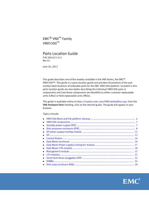
<strong>EMC</strong> ® VNX Family<br />
<strong>VNX5300</strong> <br />
<strong>Parts</strong> Location <strong>Guide</strong><br />
P/N 300-013-313<br />
Rev 01<br />
June 26, 2012<br />
This guide describes one of five models available in the VNX Series, the <strong>EMC</strong> ®<br />
<strong>VNX5300</strong>. This guide is a parts location guide and provides illustrations of the part<br />
number label locations of orderable parts for the <strong>EMC</strong> <strong>VNX5300</strong> platform. Included in this<br />
parts location guide are also tables describing the individual <strong>VNX5300</strong> parts or<br />
components and how these components are identified as either customer replaceable<br />
units (CRUs) or field replaceable units (FRUs).<br />
This guide is available online at https://mydocs.emc.com/VNX/relatedDocs.jsp. From the<br />
VNX Hardware <strong>Parts</strong> heading, click on the desired guide. The guide will appear in your<br />
browser.<br />
Topics include:<br />
◆ <strong>VNX5300</strong> Block and File platform stackup ................................................................. 4<br />
◆ <strong>VNX5300</strong> components .............................................................................................. 7<br />
◆ Standby power supply (SPS) ..................................................................................... 7<br />
◆ Disk processor enclosure (DPE) ................................................................................. 8<br />
◆ SP power supply/cooling module............................................................................ 12<br />
◆ SP........................................................................................................................... 13<br />
◆ Control Station........................................................................................................ 16<br />
◆ Data Mover enclosure ............................................................................................. 16<br />
◆ Data Mover Power supply/cooling fan module......................................................... 17<br />
◆ Data Mover CPU module.......................................................................................... 18<br />
◆ Management module .............................................................................................. 21<br />
◆ I/O modules............................................................................................................ 21<br />
◆ Small form-factor pluggable (SFP) ........................................................................... 32<br />
◆ DIMMs .................................................................................................................... 35<br />
◆ Disk-array enclosure (DAE) ...................................................................................... 39
Product software and hardware release revisions<br />
IMPORTANT<br />
2 <strong>EMC</strong> <strong>VNX5300</strong> <strong>Parts</strong> Location <strong>Guide</strong><br />
The part numbers listed in this guide are for reference only. Part numbers can change over<br />
time, and this document does not keep pace with those changes. The <strong>EMC</strong> parts inventory<br />
system will automatically substitute for the latest part numbers as required.<br />
Product software and hardware release revisions<br />
Revision history<br />
Where to get help<br />
As part of an effort to improve its product lines, <strong>EMC</strong> periodically releases revisions of its<br />
software and hardware. Therefore, some functions described in this document might not<br />
be supported by all versions of the software or hardware currently in use. The product<br />
release notes provide the most up-to-date information on product features.<br />
Contact your <strong>EMC</strong> representative if a product does not function properly or does not<br />
function as described in this document.<br />
Note: This document was accurate at publication time. New versions of this document<br />
might be released on the <strong>EMC</strong> online support website. Check the <strong>EMC</strong> online support<br />
website to ensure that you are using the latest version of this document.<br />
The following table presents the revision history of this document:<br />
Revision Date Description<br />
A01 June 26, 2012 First release of the <strong>VNX5300</strong> <strong>Parts</strong> Location<br />
<strong>Guide</strong> with a document part number<br />
<strong>EMC</strong> support, product, and licensing information can be obtained as follows:<br />
Product information — For documentation, release notes, software updates, or<br />
information about <strong>EMC</strong> products, licensing, and service, go to the <strong>EMC</strong> online support<br />
website (registration required) at:<br />
https://Support.<strong>EMC</strong>.com<br />
Technical support — For technical support, go to <strong>EMC</strong> online support and select Support.<br />
On the Support page, you will see several options, including one to create a service<br />
request. Note that to open a service request, you must have a valid support agreement.<br />
Contact your <strong>EMC</strong> sales representative for details about obtaining a valid support<br />
agreement or with questions about your account.
How this document is organized<br />
Related documentation<br />
The major sections of this guide are listed in the following table.<br />
Title Description<br />
“<strong>VNX5300</strong> Block and File<br />
platform stackup” on page 4<br />
“<strong>VNX5300</strong> components” on<br />
page 7<br />
“Standby power supply (SPS)”<br />
on page 7<br />
“Disk processor enclosure<br />
(DPE)” on page 8<br />
How this document is organized<br />
Describes and shows the front and rear views of a typical<br />
<strong>VNX5300</strong>.<br />
Provides a description of the components that comprise a<br />
<strong>VNX5300</strong>. Along with a description, illustrations of each<br />
component are also shown.<br />
Describes and illustrates the part number label locations of the<br />
SPS.<br />
Describes and illustrates the part number label locations of the<br />
DPE and the components that comprise the DPE.<br />
“Control Station” on page 16 Describes and illustrates the part number label locations of the<br />
CS.<br />
“Data Mover enclosure” on<br />
page 16<br />
Describes and illustrates the part number label locations of the<br />
DME and the management module.<br />
“I/O modules” on page 21 Describes and illustrates the part number label locations of the<br />
I/O modules that comprise the DPE and the DME.<br />
“Small form-factor pluggable<br />
(SFP)” on page 32<br />
Describes and illustrates the part number label locations of the<br />
SFP transceiver modules used in the DME.<br />
“DIMMs” on page 35 Describes and illustrates the part number label locations of the<br />
memory module or dual-inline memory modules (DIMMs) used<br />
in the DPE and the DME.<br />
“Disk-array enclosure (DAE)” on<br />
page 39<br />
Describes and illustrates the part number label locations of the<br />
two types of DAEs available for the <strong>VNX5300</strong>.<br />
<strong>EMC</strong> provides the ability to create step-by-step planning, installation, and maintenance<br />
instructions tailored to your environment. To create VNX customized documentation, go<br />
to: https://mydocs.emc.com/VNX/.<br />
To download a PDF copy of the desired publication, go to the following sections:<br />
◆ For hardware-related books, go to the About VNX section, and then select Learn about<br />
VNX. Next, follow the steps in the wizard.<br />
◆ For technical specifications, go to the About VNX section, and then select View<br />
technical specifications. Next, follow the steps in the wizard.<br />
◆ For installation, adding, or replacing tasks, go to the VNX tasks section, and then<br />
select the appropriate heading. For example, to download a PDF copy of the <strong>VNX5300</strong><br />
Block Installation <strong>Guide</strong>, go to Install VNX and follow the steps in the wizard.<br />
<strong>EMC</strong> <strong>VNX5300</strong> <strong>Parts</strong> Location <strong>Guide</strong> 3
<strong>VNX5300</strong> Block and File platform stackup<br />
4 <strong>EMC</strong> <strong>VNX5300</strong> <strong>Parts</strong> Location <strong>Guide</strong><br />
◆ For server-related tasks, go to the Server tasks for the <strong>VNX5300</strong>, VNX5500, VNX5700,<br />
and VNX7500 section, and then select the appropriate heading. For example, to<br />
download a PDF copy of Adding or replacing hardware, go to Add or replace hardware<br />
and follow the steps in the wizard.<br />
<strong>VNX5300</strong> Block and File platform stackup<br />
Front view<br />
The <strong>VNX5300</strong> Block and File platform comprises a 1U standby power supply (SPS), a 3U<br />
disk processor enclosure (DPE), a 1U Control Station, a 2U Data Mover enclosure.<br />
Note: Throughout this guide, figure references are placed in the Part number label location<br />
heading of tables because some of the tables have part number locations, as described in<br />
Table 4 on page 11 and some do not, as described in Table 1 on page 8, for example. This<br />
format is used throughout this guide.<br />
On the front, viewing from top to bottom, a Block and File <strong>VNX5300</strong> platform includes the<br />
following hardware:<br />
◆ One 2U Data Mover enclosure with one to two Data Movers<br />
◆ One to two 1U Control Stations<br />
◆ One 3U DPE chassis with either a:<br />
• 15 (3.5-inch) disk drives (hot-swappable)<br />
or,<br />
• 25 (2.5-inch) disk drives (hot-swappable)<br />
◆ One dual 1U standby power supply (SPS)
<strong>VNX5300</strong> Block and File platform stackup<br />
Figure 1 shows an example of the front of a Block and File <strong>VNX5300</strong> platform with a 3U, 15<br />
(3.5-inch) DPE.<br />
Figure 1 Example of the Block and File <strong>VNX5300</strong> platform with a 3U, 15 (3.5-inch) DPE (front view)<br />
Figure 2 shows an example of the front of a Block and File <strong>VNX5300</strong> platform with a 3U, 25<br />
(2.5-inch) DPE.<br />
0<br />
DVD<br />
DVD<br />
DVD<br />
DVD<br />
AC AC AC AC<br />
AC AC AC AC<br />
0<br />
1 2 3 4 5 6 7 8 9 10 11 12 13 14 15 16 17 18 19 20 21 22 23 24<br />
Data Mover<br />
Enclosure 0<br />
Control Station 1<br />
(optional)<br />
Control Station 0<br />
3U, 15 (3.5-inch)<br />
disk processor<br />
enclosure (DPE)<br />
SPS<br />
Data Mover<br />
enclosure 0<br />
VNX-000562<br />
Control Station 1<br />
(optional)<br />
Control Station 0<br />
3U, 25 (2.5-inch)<br />
disk processor<br />
enclosure (DPE)<br />
SPS<br />
VNX-000612<br />
Figure 2 Example of the Block and File <strong>VNX5300</strong> platform with a 3U, 25 (2.5-inch) DPE (front view)<br />
24<br />
<strong>EMC</strong> <strong>VNX5300</strong> <strong>Parts</strong> Location <strong>Guide</strong> 5
<strong>VNX5300</strong> Block and File platform stackup<br />
Rear view<br />
6 <strong>EMC</strong> <strong>VNX5300</strong> <strong>Parts</strong> Location <strong>Guide</strong><br />
Note: A Block and File <strong>VNX5300</strong> platform has one 2U Data Mover enclosure, one 1U<br />
Control Station, one 3U DPE, and one dual 1U SPS. In the following sections, the<br />
illustrations and corresponding tables describe these individual components. These<br />
descriptions are for illustrative purposes only.<br />
On the rear, viewing from top to bottom, a Block and File <strong>VNX5300</strong> platform includes the<br />
following hardware components:<br />
◆ One 2U Data Mover enclosure with two Data Movers<br />
◆ One to two 1U Control Stations<br />
◆ One 3U DPE with two storage processors (SP A and B); each SP has one CPU module<br />
and one power supply/cooling module<br />
◆ One dual 1U SPS<br />
Figure 3 shows an example of the rear of a Block and File <strong>VNX5300</strong> platform.<br />
B<br />
0 1 2 3<br />
0 1 2 3<br />
2 3 4 5<br />
0 1 2 3<br />
PART NUMBER<br />
REV A09 A<br />
0 1 2 3<br />
0 1 2 3<br />
8Gb 6Gb<br />
fibre SAS<br />
1 X4<br />
Figure 3 Example of Block and File <strong>VNX5300</strong> platform (rear view)<br />
0 1 2 3<br />
PART NUMBER<br />
REV A09 A<br />
6Gb SAS<br />
0 X4<br />
0 1 2 3<br />
A<br />
A<br />
CS<br />
CS<br />
0 1 2 3<br />
0 1 2 3<br />
2 3 4 5<br />
0 1 2 3<br />
B MGMT<br />
B MGMT<br />
PART NUMBER<br />
REV A09 A<br />
0 1 2 3<br />
0 1 2 3<br />
8Gb 6Gb<br />
fibre SAS<br />
1 X4<br />
0 1 2 3<br />
PART NUMBER<br />
REV A09 A<br />
6Gb SAS<br />
0 X4<br />
0 1 2 3<br />
A<br />
Data Mover<br />
Enclosure 0<br />
Control Station 1<br />
(optional)<br />
Control Station 0<br />
Disk<br />
processor<br />
enclosure<br />
SPS<br />
VNX-000563
<strong>VNX5300</strong> components<br />
<strong>VNX5300</strong> components<br />
Viewing from the bottom to the top, the Block and File <strong>VNX5300</strong> platform includes several<br />
components. The following sections discuss each component in an illustration and table.<br />
The illustration will show or point out the location of the part number label on the<br />
component. The table will list the part number, describe the component or part, and tell<br />
you if it is a FRU or CRU or both.<br />
◆ Dual 1U standby power supply (SPS)<br />
◆ 3U Disk processor enclosure (DPE)<br />
• 3U, 15 (3.5-inch) disk drive<br />
• 3U, 25 (2.5-inch) disk drive<br />
• Storage processor (SP) power supply/cooling module<br />
• Storage processor<br />
◆ 1U Control Station (CS)<br />
◆ 2U Data Mover enclosure (DME)<br />
• DME power supply/cooling module<br />
• DME CPU module<br />
• Management module<br />
◆ I/O modules<br />
• SP I/O modules<br />
• DME I/O modules<br />
◆ Small form-factor pluggable (SFP) transceiver modules<br />
◆ Dual in-line memory modules (DIMMs)<br />
• SP DIMMs<br />
• DME DIMMs<br />
◆ 2U or 3U Disk-array enclosures (DAEs)<br />
• 3U, 15 (3.5-inch) disk drive<br />
• 2U, 25 (2.5-inch) disk drive<br />
Standby power supply (SPS)<br />
The Block and File <strong>VNX5300</strong> platform can support up to two standby power supplies or a<br />
dual 1U SPS to provide temporary emergency power to the Block and File <strong>VNX5300</strong><br />
platform. Part numbers for the 1U SPS are only on the rear of the product.<br />
Figure 4 shows the part number label location on the SPS.<br />
<strong>EMC</strong> <strong>VNX5300</strong> <strong>Parts</strong> Location <strong>Guide</strong> 7
Disk processor enclosure (DPE)<br />
8 <strong>EMC</strong> <strong>VNX5300</strong> <strong>Parts</strong> Location <strong>Guide</strong><br />
Figure 4 Example of a dual 1U SPS<br />
Disk processor enclosure (DPE)<br />
Front view<br />
DPE 3U, 15 (3.5-inch) disk drive<br />
Table 5 lists the part number label location, part number, description, and whether it is a<br />
FRU or CRU.<br />
Table 1 SPS part number<br />
The 3U DPE has part numbers visible on both the front and rear.<br />
The 3U DPE supports two types of disk drive carriers:<br />
◆ 3U, 15 (3.5-inch) disk drives<br />
◆ 3U, 25 (2.5-inch) disk drives<br />
S/N<br />
900-XXX-0014 0082<br />
REV A00<br />
Figure 5 on page 9 shows the front view of the DPE 3U, 15 (3.5-inch) disk drives.<br />
Note: You can visually distinguish disk module kinds by their type, capacity, and speed<br />
labels, and by the design of the latch and handle on each disk module (Figure 5 on<br />
page 9).<br />
S/N<br />
900-XXX-0014 0082<br />
Part Number (P/N) label CNS-001545<br />
Part number label<br />
location (Figure 4<br />
on page 8) Part number Description FRU CRU<br />
078-000-084<br />
078-000-085<br />
DC standby power supply (SPS)<br />
1200W<br />
REV A00<br />
� �
Figure 5 Example of the DPE 3U, 15 (3.5-inch) disk drive (front view)<br />
Disk processor enclosure (DPE)<br />
Note: Figure 5 is for illustrative purposes only. The front of the disk modules may be a little<br />
different than the ones in your particular cabinet.<br />
Table 2 is an example of the parts available for the 3U, 15 (3.5-inch) DPE and lists the part<br />
number label location, part number, description, and whether it is a FRU or CRU.<br />
IMPORTANT<br />
Part Number Label<br />
Due to the extensive variety of disk module types, Table 2 only lists two disk types. <strong>EMC</strong><br />
recommends that you refer to the latest <strong>EMC</strong> VNX5100 and <strong>VNX5300</strong> Series Storage<br />
Systems Disk and OE Matrix <strong>Guide</strong> to ensure that you have the correct part for your<br />
configuration.<br />
Table 2 DPE 3U, 15 (3.5-inch) disk module part numbers<br />
Part number label<br />
location (Figure 5) Part number Description (see note) FRU CRU<br />
005049299 300 GB, 6 Gb/s SAS, 10k rpm � �<br />
005049301 600 GB, 6 Gb/s SAS, 15k rpm � �<br />
Note: The description field describes the disk module type, capacity, drive type, and spindle<br />
speed (rpm).<br />
VNX-000607<br />
<strong>EMC</strong> <strong>VNX5300</strong> <strong>Parts</strong> Location <strong>Guide</strong> 9
Disk processor enclosure (DPE)<br />
DPE 3U, 25 (2.5-inch) disk drive<br />
10 <strong>EMC</strong> <strong>VNX5300</strong> <strong>Parts</strong> Location <strong>Guide</strong><br />
Figure 6 shows the front view of the DPE 3U, 25 (2.5-inch) disk drives.<br />
Note: You can visually distinguish disk module kinds by their type, capacity, and speed<br />
labels, and by the design of the latch and handle on each disk module (Figure 6).<br />
0<br />
Part Number Label<br />
0<br />
Figure 6 Example of the DPE 3U, 25 (2.5-inch) disk drive (front view)<br />
Note: Figure 6 is for illustrative purposes only. The front of the disk modules may be a little<br />
different than the ones in your particular cabinet.<br />
Table 3 is an example of the parts available for the 3U, 25 (2.5-inch) DPE and lists the part<br />
number label location, part number, description, and whether it is a FRU or CRU.<br />
IMPORTANT<br />
1 2 3 4 5 6 7 8 9 10 11 12 13 14 15 16 17 18 19 20 21 22 23 24<br />
Due to the extensive variety of disk module types, Table 3 only lists two disk types. <strong>EMC</strong><br />
recommends that you refer to the latest <strong>EMC</strong> VNX5100 and <strong>VNX5300</strong> Series Storage<br />
Systems Disk and OE Matrix <strong>Guide</strong> to ensure that you have the correct part for your<br />
configuration.<br />
Table 3 DPE 3U, 25 (2.5-inch) disk module part numbers<br />
Part number label<br />
location (Figure 6) Part number Description (see note) FRU CRU<br />
005049292 300 GB, 6 Gb/s SAS, 10k rpm � �<br />
005049294 600 GB, 6 Gb/s SAS, 10k rpm � �<br />
Note: The description field describes the disk module type, capacity, drive type, and spindle<br />
speed (rpm).<br />
24<br />
VNX-000603
Rear view<br />
Disk processor enclosure (DPE)<br />
Figure 7 shows the rear view of the 3U disk processor enclosure (DPE) with two storage<br />
processors (SP A and B).<br />
1 2<br />
B<br />
2 3 4 5<br />
3 4<br />
PART NUMBER<br />
REV A09 A<br />
8Gb 6Gb<br />
fibre SAS<br />
1 X4<br />
6Gb SAS<br />
0 X4<br />
SP B<br />
Figure 7 Example of 3U DPE with two SPs (A and B)<br />
2 3 4 5<br />
8Gb 6Gb<br />
fibre SAS<br />
1 X4<br />
Table 4 lists the part number label location, part number, description, and whether it is a<br />
FRU or CRU.<br />
Table 4 DPE chassis and SP part numbers<br />
0 1 2 3<br />
PART NUMBER<br />
REV A09 A<br />
0 1 2 3<br />
6Gb SAS<br />
0 X4<br />
SP A<br />
Part number label<br />
location (Figure 7<br />
on page 11) Part number Description FRU CRU<br />
1 100-562-503<br />
100-563-138<br />
3U, 15 disk drive chassis and<br />
midplane<br />
3U, 25 disk drive chassis and<br />
midplane<br />
2 110-140-408B SP, 1.6 GHZ QC CPU, 8-GB RAM (for<br />
a closer view, see Figure 9 on<br />
page 13)<br />
110-140-400B SP, 1.6-GHz GHZ QC CPU, DIMMs<br />
(for a closer view, see Figure 9 on<br />
page 13)<br />
3 071-000-529 1U AC/DC, 875W, dual power<br />
supply (for a closer view, see<br />
Figure 8 on page 12)<br />
PART NUMBER<br />
REV A09 A<br />
PART NUMBER<br />
REV A09 A<br />
<strong>EMC</strong> <strong>VNX5300</strong> <strong>Parts</strong> Location <strong>Guide</strong> 11<br />
�<br />
�<br />
�<br />
0 1 2 3<br />
�<br />
�<br />
� �<br />
4 303-092-102B Four-port 8-Gb/s FC (2/4/8 Gb/s) � �<br />
303-141-100A 1 Four-port 1-Gb/s copper iSCSI I/O<br />
module<br />
303-081-105B 2 Two-port 10-Gb/s optical with iSCSI<br />
protocol I/O module<br />
� �<br />
� �<br />
0 1 2 3<br />
A<br />
VNX-000614
Disk processor enclosure (DPE)<br />
SP power supply/cooling module<br />
12 <strong>EMC</strong> <strong>VNX5300</strong> <strong>Parts</strong> Location <strong>Guide</strong><br />
Table 4 DPE chassis and SP part numbers (continued)<br />
Part number label<br />
location (Figure 7<br />
on page 11) Part number Description FRU CRU<br />
303-142-100A 3 Two-port 10-Gb/s FCoE I/O module � �<br />
303-164-104D-01 4 Two-port 10-Gb/s RJ-45 Base-T<br />
iSCSI/IP<br />
100-562-718 I/O module filler panel includes a<br />
Do Not Remove label<br />
Figure 8 shows the part number label location on power supply/cooling module used in<br />
the Block and File <strong>VNX5300</strong> platform SPs (A and B).<br />
Figure 8 Example of a power supply module/cooling<br />
Note: This filler panel is only used<br />
when the SP I/O module slots are<br />
empty.<br />
� �<br />
1. This part is not shown in the example DPE illustration in Figure 7. For a closer view, go to Figure 21 on<br />
page 24.<br />
2. This part is not shown in the example DPE illustration in Figure 7. For a closer view, go to Figure 22 on<br />
page 25.<br />
3. This part is not shown in the example DPE illustration in Figure 7. For a closer view, go to Figure 23 on<br />
page 26.<br />
4. This part is not shown in the example DPE illustration in Figure 7. For a closer view, go to Figure 24 on<br />
page 27.<br />
Part number (P/N) label<br />
VNX-000608<br />
Table 5 lists the part number label location, part number, description, and whether it is a<br />
FRU or CRU.<br />
Table 5 Power supply module/cooling fan part number<br />
Part number label<br />
location<br />
(Figure 8) Part number Description FRU CRU<br />
071-000-529 1U AC/DC, 875W, dual power<br />
supply<br />
�
SP<br />
Figure 9 shows the part number label location on the SP.<br />
Figure 9 Example of an SP<br />
2 3 4 5<br />
8Gb 6Gb<br />
fibre SAS<br />
1<br />
X4<br />
Disk processor enclosure (DPE)<br />
Table 6 lists the part number label location, part number, description, and whether it is a<br />
FRU or CRU.<br />
Table 6 SP CPU part number<br />
SP part number (P/N) label<br />
PART NUMBER<br />
REV A09 A<br />
PART NUMBER<br />
REV A09 A<br />
6Gb SAS<br />
0 X4<br />
To access the SP CPU, you must first remove the SP from the 3U DPE (Figure 10 on<br />
page 14). Then, you must remove the power supply/cooling fan modules (Figure 11 on<br />
page 14).<br />
0 1 2 3<br />
0 1 2 3<br />
VNX-000613<br />
Part number label<br />
location (Figure 9<br />
on page 13) Part number Description FRU CRU<br />
110-140-408B SP 1.6-GHZ CPU, with 8 GB of<br />
memory<br />
110-140-400B SP 1.6-GHZ CPU, without memory �<br />
<strong>EMC</strong> <strong>VNX5300</strong> <strong>Parts</strong> Location <strong>Guide</strong> 13
Disk processor enclosure (DPE)<br />
14 <strong>EMC</strong> <strong>VNX5300</strong> <strong>Parts</strong> Location <strong>Guide</strong><br />
Figure 10 shows the SP partially removed from the front of the DPE.<br />
Figure 10 Example of removing the SP from the 3U DPE<br />
Figure 11 shows the power supply/cooling module being removed from the SP.<br />
Figure 11 Example of removing the SP power supply/cooling module from the SP<br />
CL4594<br />
CL4595
Disk processor enclosure (DPE)<br />
The part number labels for the SP and the SP CPU module in Figure 12 are listed in Table 6<br />
on page 13. The SP CPU part number label is located on the motherboard of the SP CPU<br />
(Figure 12).<br />
SP Power supply/cooling module<br />
SP<br />
part number (P/N) label<br />
Figure 12 Example of the SP CPU with power supply/cooling module set aside<br />
SP CPU<br />
part number (P/N) label<br />
VNX-000665<br />
<strong>EMC</strong> <strong>VNX5300</strong> <strong>Parts</strong> Location <strong>Guide</strong> 15
Control Station<br />
Control Station<br />
Data Mover enclosure<br />
Front view<br />
16 <strong>EMC</strong> <strong>VNX5300</strong> <strong>Parts</strong> Location <strong>Guide</strong><br />
Figure 13 shows the part number label location on the front of the 1U Control Station.<br />
Figure 13 Example of the Control Station (front view)<br />
Table 7 lists the part number label location, part number, description, and whether it is a<br />
FRU or CRU.<br />
Table 7 Control Station front view part number<br />
Figure 14 shows the part number location on the front of the 2U Data Mover enclosure.<br />
Figure 14 Data Mover enclosure (front view)<br />
Part Number (P/N) label<br />
Part number label<br />
location<br />
(Figure 13) Part number Description FRU CRU<br />
100-520-665 Control Station (CS) 1U �<br />
1<br />
AC AC AC AC<br />
NSXXX 0000 XXX 000<br />
SN: FNM000XXX000XX<br />
NSXXX 0000 XXX 000<br />
PN: 900-XXX-0014 (NSXXX)<br />
CNS-001544<br />
2 CNS-001723
Data Mover enclosure<br />
Table 8 provides the part number label location, part number, description, and whether it<br />
is a FRU or CRU.<br />
Table 8 Data Mover enclosure front view part numbers<br />
Data Mover Power supply/cooling fan module<br />
Part number label<br />
location<br />
(Figure 14 on<br />
page 16) Part number Description FRU CRU<br />
1 071-000-543 1 Data Mover enclosure 400 W, 2U,<br />
single 12 V output power<br />
supply/cooling fan module (for a<br />
closer view, see Figure 15 on<br />
page 17)<br />
2 110-113-102B Data Mover 2.4-GHz CPU module<br />
with 6 GB of memory (for a closer<br />
view, see Figure 17 on page 19)<br />
303-113-101B Data Mover 2.4-GHz CPU module<br />
without memory (for a closer view,<br />
see Figure 17 on page 19)<br />
Figure 15 shows the part number label location on the front of the two power<br />
supply/cooling fan modules used in the Data Mover enclosure.<br />
Note: The part number label is located on the lower half of the pull handle.<br />
Figure 15 Example of a power supply module/cooling fan (front view)<br />
� �<br />
� �<br />
1. The part number label on the power supply/cooling fan module is located on the lower half of the pull<br />
handle.<br />
Part Number (P/N) label<br />
AC AC<br />
CNS-001682<br />
<strong>EMC</strong> <strong>VNX5300</strong> <strong>Parts</strong> Location <strong>Guide</strong> 17
Data Mover enclosure<br />
Data Mover CPU module<br />
18 <strong>EMC</strong> <strong>VNX5300</strong> <strong>Parts</strong> Location <strong>Guide</strong><br />
Table 9 lists the part number label location, part number, description, and whether it is a<br />
FRU or CRU.<br />
Table 9 Power supply module/cooling fan part number<br />
Part number label<br />
location<br />
(Figure 15 on<br />
page 17) Part number Description FRU CRU<br />
To access the Data Mover CPU, you must first remove the power supply/cooling fan<br />
modules (Figure 16).<br />
1<br />
071-000-543 Data Mover enclosure 400 W, 2U,<br />
single 12 V output power<br />
supply/cooling fan module<br />
Figure 16 Example of the Data Mover power supply/cooling fan module removal<br />
� �<br />
Figure 17 on page 19 shows the Data Mover CPU module partially removed from the front<br />
of the Data Mover enclosure with the two power supply/cooling fan modules set aside.<br />
The part number label for the Data Mover CPU module in Figure 17 on page 19 is listed in<br />
Table 10 on page 19.<br />
Note: The DM CPU part numbers are located on the DM CPU sheet metal. You must remove<br />
the DM from the DM enclosure (Figure 17 on page 19). You can also find the DM CPU part<br />
number label located inside the DM CPU by looking through the blue plastic DIMM cover.<br />
The part number label is located on the motherboard.<br />
1<br />
2 2 2<br />
2<br />
1<br />
1<br />
CL3972
Rear view<br />
Part Number (P/N) label<br />
Figure 17 Example of the Data Mover CPU being removed from a Data Mover enclosure<br />
Table 10 Data Mover CPU part number<br />
Data Mover enclosure<br />
Part number label<br />
location Part number Description FRU CRU<br />
Figure 14 on<br />
page 16<br />
Figure 17 on<br />
page 19<br />
110-113-102B Data Mover 2.4-GHz CPU module<br />
with 6 GB of memory<br />
303-113-101B Data Mover 2.4-GHz CPU module<br />
without memory<br />
Figure 18 shows the part number label location on the rear of a Data Mover enclosure.<br />
0 1 2 3<br />
Power/cooling modules<br />
Figure 18 Data Mover enclosure (rear view)<br />
0 1 2 3<br />
1<br />
0 1 2 3<br />
2<br />
1<br />
0 1 2 3<br />
0 1 2 3<br />
1<br />
2 2<br />
1<br />
Data Mover enclosure<br />
Data Mover CPU CNS-001683<br />
1 2 3 4<br />
0 1 2 3<br />
0 1 2 3<br />
0 1 2 3<br />
<strong>EMC</strong> <strong>VNX5300</strong> <strong>Parts</strong> Location <strong>Guide</strong> 19<br />
�<br />
0 1 2 3<br />
0 1 2 3<br />
5<br />
CNS-001724
Data Mover enclosure<br />
20 <strong>EMC</strong> <strong>VNX5300</strong> <strong>Parts</strong> Location <strong>Guide</strong><br />
Table 11 lists the part number label location, part number, description, and whether it is a<br />
FRU or CRU.<br />
Table 11 Data Mover enclosure part numbers rear view<br />
Part number label<br />
location<br />
(Figure 18 on<br />
page 19) Part number Description FRU CRU<br />
1 100-562-178 Data Mover enclosure (empty) �<br />
2 110-130-100B Management module (for a closer<br />
view, see Figure 19 on page 21)<br />
3 303-092-102B Four-port 8-Gb/s Fibre Channel (FC)<br />
I/O module (for a closer view, see<br />
Figure 20 on page 23)<br />
4 303-122-100A Two-port 1-Gb/s copper plus<br />
two-port 1G/bs optical I/O module<br />
(for a closer view, see Figure 25 on<br />
page 28)<br />
5 100-562-718 I/O module filler panel includes Do<br />
Not Remove label<br />
Note: This filler panel is only used<br />
when the Data Mover I/O module<br />
slots are empty.<br />
303-121-100A 1 Four-port 10/100/1000 Base-T<br />
copper I/O module (for a closer<br />
view, see Figure 27 on page 30)<br />
303-081-103B 2 Two-port 10-Gb/s Ethernet optical<br />
I/O module (for a closer view, see<br />
Figure 26 on page 29)<br />
303-195-100B 3 Two-port 10-Gb/s Ethernet optical<br />
or Twinax I/O module (for a closer<br />
view, see Figure 28 on page 31)<br />
303-164-104D-01 4 Two-port 10-Gb/s RJ-45 Base-T<br />
iSCSI/IP (for a closer view, see<br />
Figure 24 on page 27)<br />
� �<br />
� �<br />
� �<br />
� �<br />
� �<br />
� �<br />
� �<br />
� �<br />
1. This part is not shown in the example Data Mover enclosure illustration in Figure 18 on page 19. For a closer<br />
view, go to Figure 27 on page 30.<br />
2. This part is not shown in the example Data Mover enclosure illustration in Figure 18 on page 19. For a closer<br />
view, go to Figure 22 on page 25.<br />
3. This part is not shown in the example Data Mover enclosure illustration in Figure 18 on page 19. For a closer<br />
view, go to Figure 28 on page 31.<br />
4. This part is not shown in the example Data Mover enclosure illustration in Figure 18 on page 19. For a closer<br />
view, go to Figure 24 on page 27.
Management module<br />
I/O modules<br />
I/O modules<br />
Figure 19 shows the part number label location on the rear of the Data Mover enclosure<br />
management module used in the Data Mover enclosure.<br />
2<br />
0<br />
Part Number (P/N label<br />
#<br />
1<br />
CNS-001684<br />
Figure 19 Example of the Data Mover enclosure management module<br />
Table 12 lists the part number label location, part number, description, and whether it is a<br />
FRU or CRU.<br />
Table 12 Data Mover enclosure management module part number<br />
Part number label<br />
location<br />
(Figure 19) Part number Description FRU CRU<br />
110-130-100B Management module � �<br />
In the Block and File <strong>VNX5300</strong> platform, I/O modules are used in the disk processor<br />
enclosure (DPE) storage processors (SP A and B) and in the Data Movers of the Data Mover<br />
enclosure.<br />
Each I/O module is identified by a part number, type of ports (copper or optical), latch<br />
handle label, and color label on top of the latch handle. For ease of identification,<br />
Table 13 on page 22 describes each I/O module type in the <strong>VNX5300</strong>.<br />
<strong>EMC</strong> <strong>VNX5300</strong> <strong>Parts</strong> Location <strong>Guide</strong> 21
I/O modules<br />
SP<br />
22 <strong>EMC</strong> <strong>VNX5300</strong> <strong>Parts</strong> Location <strong>Guide</strong><br />
Table 13 I/O module types for <strong>VNX5300</strong><br />
I/O module Part number Ports<br />
Five types of I/O modules are supported in the SP:<br />
◆ “Four-port 8-Gb/s Fibre Channel (FC) I/O module” on page 23<br />
◆ “Four-port 1-Gb/s copper iSCSI I/O module” on page 24<br />
◆ “Two-port 10-Gb/s optical (w/iSCSI protocol) I/O module” on page 25<br />
◆ “Two-port 10-Gb/s Fibre Channel over Ethernet (FCoE) I/O module” on page 26<br />
◆ “Two-port 10-Gb/s RJ-45 Base-T iSCSI/IP I/O module” on page 27<br />
Data Mover<br />
Seven types of I/O modules are supported in the Data Mover:<br />
◆ “Four-port 8-Gb/s Fibre Channel (FC) I/O module” on page 23<br />
◆ “Two-port 10-Gb/s Fibre Channel over Ethernet (FCoE) I/O module” on page 26<br />
◆ “Two-port 10-Gb/s RJ-45 Base-T iSCSI/IP I/O module” on page 27<br />
◆ “Two-port 1-Gb/s copper plus two-port 1-Gb/s optical I/O module” on page 28<br />
◆ “Two-port 10-Gb/s optical I/O module” on page 29<br />
◆ “Four-port 1-Gb/s copper I/O module” on page 30<br />
◆ “Two-port 10-Gb/s optical I/O module” on page 31<br />
Latch handle<br />
label<br />
Latch<br />
handle<br />
label color<br />
Four-port 8-Gb/s FC 303-092-102B Optical 8 Gb Fibre Silver<br />
Four-port 1-Gb/s 303-141-100A Copper 1 GbE iSCSI/TOE Orange<br />
Two-port 10-Gb/s (w/iSCSI) 303-081-105B Optical 10 GbE Orange<br />
Two-port 10-Gb/s FCoE 303-142-100A Optical 10 GbE/FCoE Green<br />
Two-port 10-Gb/s RJ-45<br />
Base-T iSCSI/IP<br />
Two-port 1-Gb/s copper<br />
plus two-port 1-Gb/s<br />
optical<br />
303-164-104D-01 Copper 10 GbE Base-T Orange<br />
303-122-100A or B Copper<br />
plus<br />
optical<br />
1 GbE Brown<br />
Two-port 10-Gb/s 303-081-103B or C Optical 10 GbE iSCSI or<br />
10 GbE v2<br />
Orange<br />
Two-port 10-Gb/s 303-195-100C-01 Optical 10 GbE v3 Orange<br />
Four-port 10/100/1000<br />
Ethernet<br />
303-121-100A Copper 1 GbE Brown
I/O modules<br />
The following sections describe these I/O modules and the part numbers. Refer to these<br />
when determining which part number you need for either the SP or Data Mover that the<br />
I/O module goes in.<br />
Four-port 8-Gb/s Fibre Channel (FC) I/O module<br />
Figure 20 shows the part number label location on the four-port 8-Gb/s Fibre Channel (FC)<br />
I/O module (labeled 8 Gb Fibre on the latch handle).<br />
Part Number (P/N) Label<br />
CNS-001698<br />
Figure 20 Example of the four-port 8-Gb/s FC I/O module<br />
Table 14 lists the part number label location, part number, description, and whether it is a<br />
FRU or CRU.<br />
Table 14 Four-port 8-Gb/s FC I/O module part numbers<br />
Part number label<br />
location<br />
(Figure 20) Part number Description FRU CRU<br />
303-092-102B Four-port 8-Gb/s FC (2/4/8 Gb/s) � �<br />
<strong>EMC</strong> <strong>VNX5300</strong> <strong>Parts</strong> Location <strong>Guide</strong> 23
I/O modules<br />
Four-port 1-Gb/s copper iSCSI I/O module<br />
24 <strong>EMC</strong> <strong>VNX5300</strong> <strong>Parts</strong> Location <strong>Guide</strong><br />
Figure 21 shows the part number label location on the four-port 1-Gb/s copper iSCSI I/O<br />
module (labeled 1 GbE iSCSI/TOE on the latch handle).<br />
Part Number (P/N) Label<br />
CNS-001699<br />
Figure 21 Example of the four-port 1-Gb/s copper iSCSI I/O module<br />
Table 15 lists the part number label location, part number, description, and whether it is a<br />
FRU or CRU.<br />
Table 15 Four-port 1-Gb/s copper iSCSI I/O module part number<br />
Part number label<br />
location<br />
(Figure 21) Part number Description FRU CRU<br />
303-141-100A Four 1-Gb/s copper iSCSI ports � �
Two-port 10-Gb/s optical (w/iSCSI protocol) I/O module<br />
I/O modules<br />
Figure 22 shows the part number label location on the two-port 10-Gb/s optical (w/iSCSI<br />
protocol) I/O module (labeled 10 GbE on the latch handle).<br />
Part Number (P/N) Label<br />
CNS-001700<br />
Figure 22 Example of the two-port 10-Gb/s optical (w/iSCSI protocol) I/O module<br />
Table 16 lists the part number label location, part number, description, and whether it is a<br />
FRU or CRU.<br />
Table 16 Two-port 10-Gb-s optical (w/iSCSI protocol) I/O module part number<br />
Part number label<br />
location<br />
(Figure 22) Part number Description FRU CRU<br />
303-081-105B Two-port 10-Gb/s optical (w/iSCSI<br />
protocol) I/O module<br />
� �<br />
<strong>EMC</strong> <strong>VNX5300</strong> <strong>Parts</strong> Location <strong>Guide</strong> 25
I/O modules<br />
Two-port 10-Gb/s Fibre Channel over Ethernet (FCoE) I/O module<br />
26 <strong>EMC</strong> <strong>VNX5300</strong> <strong>Parts</strong> Location <strong>Guide</strong><br />
Figure 23 shows the part number label location on the two-port 10-Gb/s Fibre Channel<br />
over Ethernet (FCoE) I/O module (labeled 10 GbE/FCoE on the latch handle).<br />
Part Number (P/N) Label<br />
CNS-001700<br />
Figure 23 Example of the two-port 10-Gb/s FCoE I/O module with SFPs 1<br />
Note: The 10-Gb/s FCoE I/O module requires VNX OE for File version 7.0.35.3 or later.<br />
Table 17 shows the part number label location, part number, description, and whether it<br />
is a FRU or CRU.<br />
Table 17 Two-port 10-Gb/s FCoE I/O module part numbers<br />
Part number label<br />
location<br />
(Figure 23) Part number Description FRU CRU<br />
303-142-100A Two-port 10-Gb/s FCoE � �<br />
1. The FCoE I/O module can also use twinaxial (Twinax) cables. Twinax is a type of cable similar to coax, but with two inner conductors<br />
instead of one. These cables will be supplied in lieu of SFPs when so ordered.
Two-port 10-Gb/s RJ-45 Base-T iSCSI/IP I/O module<br />
I/O modules<br />
Figure 26 shows the part number label location on the two-port 10-Gb/s RJ-45 Base-T<br />
iSCSI/IP I/O module (labeled 10 GbE BASE-T on the latch handle).<br />
Part Number (P/N) Label<br />
VNXe-000753<br />
Figure 24 Example of the two-port 10-Gb/s RJ-45 Base-T iSCSI/IP I/O module<br />
Note: The two-port 10-Gb/s RJ-45 Base-T iSCSI/IP I/O module requires VNX OE for File 7.1<br />
or later.<br />
Table 20 shows the part number label location, part number, description, and whether it<br />
is a FRU or CRU.<br />
Table 18 Two-port 10-Gb/s RJ-45 RJ-45 Base-T iSCSI/IP I/O module part number<br />
Part number label<br />
location<br />
(Figure 24) Part number Description FRU CRU<br />
303-164-104D-01 Two-port 10-Gb/s RJ-45 Base-T<br />
iSCSI/IP I/O module<br />
� �<br />
<strong>EMC</strong> <strong>VNX5300</strong> <strong>Parts</strong> Location <strong>Guide</strong> 27
I/O modules<br />
Two-port 1-Gb/s copper plus two-port 1-Gb/s optical I/O module<br />
28 <strong>EMC</strong> <strong>VNX5300</strong> <strong>Parts</strong> Location <strong>Guide</strong><br />
Figure 25 shows the part number label location on the two-port 1-Gb/s copper plus<br />
two-port 1-Gb/s optical I/O module (labeled 1 GbE on the latch handle).<br />
Part Number (P/N) Label<br />
CNS-001701<br />
Figure 25 Example of the two-port 1-Gb/s copper plus two-port 1-Gb/s optical I/O module<br />
Table 19 lists the part number label location, part number, description, and whether it is a<br />
FRU or CRU.<br />
Table 19 Two-port 1-Gb/s copper plus two-port 1-Gb/s optical I/O module part number<br />
Part number label<br />
location<br />
(Figure 25) Part number Description FRU CRU<br />
303-122-100A or B Two-port 1-Gb/s copper plus<br />
two-port 1-Gb/s optical<br />
� �
Two-port 10-Gb/s optical I/O module<br />
Figure 26 shows the part number label location on the two-port 10-Gb/s optical I/O<br />
module (labeled 10 GbE iSCSI or 10 GbE v2 on the latch handle).<br />
Part Number (P/N) Label<br />
CNS-001700<br />
Figure 26 Example of the two-port optical I/O module<br />
I/O modules<br />
Table 20 shows the part number label location, part number, description, and whether it<br />
is a FRU or CRU.<br />
Table 20 Two-port optical I/O module part number<br />
Part number label<br />
location<br />
(Figure 26) Part number Description FRU CRU<br />
303-081-103B or C Two-port 10-Gb/s optical I/O<br />
module<br />
� �<br />
<strong>EMC</strong> <strong>VNX5300</strong> <strong>Parts</strong> Location <strong>Guide</strong> 29
I/O modules<br />
Four-port 1-Gb/s copper I/O module<br />
30 <strong>EMC</strong> <strong>VNX5300</strong> <strong>Parts</strong> Location <strong>Guide</strong><br />
Figure 27 shows the part number label location on the four-port 1-Gb/s copper I/O<br />
module (labeled 1 GbE on the latch handle).<br />
Part Number (P/N) Label<br />
CNS-001699<br />
Figure 27 Example of the four-port 1-Gb/s copper I/O module<br />
Table 21 shows the part number label location, part number, description, and whether it<br />
is a FRU or CRU.<br />
Table 21 Four-port 1-Gb/s copper I/O module part number<br />
Part number label<br />
location<br />
(Figure 27) Part number Description FRU CRU<br />
303-121-100A Four 1-Gbs copper ports � �
Two-port 10-Gb/s optical I/O module<br />
I/O modules<br />
Figure 26 shows the part number label location on the two-port 10-Gb/s optical or active<br />
Twinax I/O module (labeled 10 GbE v3 on the latch handle).<br />
Part Number (P/N) Label<br />
CNS-001700<br />
Figure 28 Example of the two-port 10-Gb/s optical I/O module<br />
Note: This two-port 10-Gb/s optical I/O module requires VNX OE for File version 7.1 or<br />
later.<br />
Table 22 shows the part number label location, part number, description, and whether it<br />
is a FRU or CRU.<br />
Table 22 Two-port 10-Gb/s optical I/O module part number<br />
Part number label<br />
location<br />
(Figure 28) Part number Description FRU CRU<br />
303-195-100C-01 Two-port 10-Gb/s Optical I/O<br />
module<br />
� �<br />
<strong>EMC</strong> <strong>VNX5300</strong> <strong>Parts</strong> Location <strong>Guide</strong> 31
Small form-factor pluggable (SFP)<br />
Small form-factor pluggable (SFP)<br />
Laser safety guidelines<br />
32 <strong>EMC</strong> <strong>VNX5300</strong> <strong>Parts</strong> Location <strong>Guide</strong><br />
Small form-factor (SFP) modules are compact, hot-pluggable transceivers inserted into<br />
the SFP or SFP+ slot of an I/O module in a Block and File <strong>VNX5300</strong> platform. This<br />
transceiver module provides uplink optical interfaces, laser send or transmit (TX) and<br />
laser receive (RX). An SFP or SFP+ transceiver module is hot-swappable. You can replace<br />
an SFP or SFP+ from the rear of the SP or Data Mover while the platform is powered up.<br />
Note: The part number is visible only when the SFP or SFP + is removed from the I/O<br />
module port.<br />
Before you install SFP or SFP+ modules in a Block and File <strong>VNX5300</strong> platform or attempt to<br />
operate or service a Block and File <strong>VNX5300</strong> platform equipped with SFP modules, you<br />
must read and observe the important safety information in this section of the document.<br />
The Block and File <strong>VNX5300</strong> platform SFP or SFP+ modules are equipped with a Class 1<br />
Laser, which emits invisible radiation. Do not stare into open optical ports. The following<br />
warnings apply to the all SFP and SFP+ modules.<br />
�������<br />
Class 1 laser product.<br />
Because invisible laser radiation can be emitted from the aperture of the port when no<br />
fiber is connected, avoid exposure to laser radiation and do not stare into open<br />
apertures.<br />
Laser radiation is present when the system is open and interlocks bypassed.<br />
Only trained and qualified personnel should be allowed to install, replace, or service this<br />
equipment.<br />
<strong>Guide</strong>lines for handling SFP and SFP+ modules<br />
Use these guidelines when you work with SFP and SFP+ modules:<br />
◆ SFP and SFP+ modules are static sensitive. Wear an ESD-preventive wrist strap that is<br />
connected to the rack in order to prevent ESD damage.<br />
◆ SFP and SFP+ modules are dust sensitive. Always store the devices with dust plugs<br />
installed in the optical bores.<br />
◆ Do not remove and insert an SFP or SFP+ module more often than is necessary.<br />
Repeated removals and insertions of an SFP or SFP+ module can shorten its useful<br />
life.
Types of SFP and SFP+ module latches<br />
Small form-factor pluggable (SFP)<br />
SFP transceiver modules can have three types of latching devices to secure the SFP or<br />
SFP+ transceiver in a port socket.<br />
◆ SFP or SFP+ transceiver with a Mylar tab latch.<br />
◆ SFP or SFP+ transceiver with an actuator button latch.<br />
◆ SFP or SFP + transceiver that has a bale-clasp latch.<br />
I/O modules using SFP or SFP+ transceiver modules<br />
Types of SFP and SFP+ modules<br />
In the <strong>VNX5300</strong> platform, the SFP or SFP+ transceiver modules are located in the ports of<br />
the following I/O modules:<br />
◆ Four-port 8-Gb/s Fibre Channel (FC) for 2, 4, and 8 Gb/s speed<br />
◆ Two-port 1-Gb/s copper plus two-port 1-Gb/s optical<br />
◆ Two-port 10-Gb/s optical (labeled 10 GbE iSCSI or 10 GbE v2)<br />
◆ Two-port 10-Gb/s optical 2 (labeled 10 GbE v3)<br />
◆ Two-port 10-Gb/s Fibre Channel over Ethernet (FCoE) 3<br />
Three types of SFP or SFP+ modules are used in the I/O modules of the Block and File<br />
<strong>VNX5300</strong> platform. Figure 29 on page 34 shows an example of an SFP or SFP+ with a bale<br />
clasp and the part number label.<br />
IMPORTANT<br />
Ensure that you correctly match the SFP or SFP+ module type with the I/O module type.<br />
2. The 10 Gb/s module (labeled 10 GbE v3) can also use active twinaxial (Twinax) cables. Twinax is a<br />
type of cable similar to coax, but with two inner conductors instead of one. These cables will be<br />
supplied in lieu of SFPs when so ordered.<br />
3. The FCoE I/O module can also use active twinaxial (Twinax) cables. Twinax is a type of cable<br />
similar to coax, but with two inner conductors instead of one. These cables will be supplied in lieu<br />
of SFPs when so ordered.<br />
<strong>EMC</strong> <strong>VNX5300</strong> <strong>Parts</strong> Location <strong>Guide</strong> 33
Small form-factor pluggable (SFP)<br />
34 <strong>EMC</strong> <strong>VNX5300</strong> <strong>Parts</strong> Location <strong>Guide</strong><br />
P/N: 000-XXX-000<br />
Figure 29 Example of an SFP with a bale clasp<br />
Part Number (P/N) label<br />
CNS-001347<br />
Table 23 lists the part number label location, part number, description, and whether it is a<br />
FRU or CRU.<br />
Note: The SFP or SFP+ part number is visible only when the SFP or SFP+ is removed from an<br />
I/O module port.<br />
Table 23 SFP and SFP+ module part numbers<br />
Part number label<br />
location<br />
(Figure 29) Part number Description FRU CRU<br />
019-078-032<br />
(SFP)<br />
019-078-041<br />
(SFP+)<br />
019-078-042<br />
(SFP+)<br />
Used in the two-port 1-Gb/s copper<br />
plus two-port 1-Gb/s Optical I/O<br />
module (see note)<br />
Used in the two-port 10-Gb/s FCoE<br />
I/O module<br />
Used in the two-port 10-Gb/s optical<br />
I/O module (latch label 10 GbE iSCSI<br />
or v2)<br />
Used in the two-port 10-Gb/s optical<br />
I/O module (latch label 10-GbE v3)<br />
Used in the four-port 8-Gb/s Fibre<br />
Channel (FC) I/O module<br />
� �<br />
� �<br />
� �<br />
� �<br />
� �<br />
Note: Only the two optical ports (physically labeled on this I/O module as 2 and 3, but logically<br />
fge-x-2 and fge-x-3) use this type of SFP.
DIMMs<br />
SP DIMMs<br />
DIMMs<br />
The Storage Processor (SP) requires 4 GB per SP or a total of 8 GB per array and the Data<br />
Mover requires 6 GB per Data Mover.<br />
The SP CPU uses SDRAM DIMMs 4 . Each SP uses three 4-GB unbuffered Double-Data-Rate<br />
3 (DDR3) type memory for a total of 12 GB per SP or 24 per DPE or array. Figure 30 on<br />
page 36 shows an example of the location of the SP DIMM slots.<br />
IMPORTANT<br />
The DIMM part numbers are visible only when you remove the DIMM from the DIMM slot.<br />
You must first take the SP out of service, disconnect any SP cables, remove the SP from the<br />
DPE, then remove the SP power supply/cooling module from the SP (see Figure 10 on<br />
page 14, Figure 11 on page 14, and Figure 12 on page 15). With the SP CPU laying on an<br />
antistatic mat, lift the DIMM cover up in the SP CPU, and then remove the DIMM from the<br />
DIMM slot. Ensure that you remove only those DIMMs that you intend to replace. For more<br />
information about removing and installing the DIMM or memory module, refer to the<br />
Replacing a memory module procedure available from the VNX Procedure Generator<br />
program.<br />
�������<br />
The DIMM memory is not hot-swappable. Before removing or replacing any DIMMs, you<br />
must follow the removing and installing the DIMM or memory module procedure<br />
described in the Replacing a memory module procedure available from the VNX<br />
Procedure Generator program.<br />
�������<br />
Note the orientation of the <strong>VNX5300</strong> Block and File platform SP DIMMs (see locations<br />
DIMM 0, DIMM 1, and DIMM 2 in Figure 30 on page 36). A label on the DIMM cover also<br />
identifies the DIMM slots as DIMM 0, DIMM 1, and DIMM 2. In the <strong>VNX5300</strong> Block and<br />
File platform, the SP DIMMs are placed in slots 0, 1, and 2.<br />
4. The term DIMM is used throughout this guide. The term DIMM is also referred to as a memory<br />
module. These terms are interchangeable and basically mean the same thing.<br />
<strong>EMC</strong> <strong>VNX5300</strong> <strong>Parts</strong> Location <strong>Guide</strong> 35
DIMMs<br />
DIMM 0<br />
DIMM 1<br />
DIMM 2<br />
36 <strong>EMC</strong> <strong>VNX5300</strong> <strong>Parts</strong> Location <strong>Guide</strong><br />
Remove / Install DIMM<br />
DIMM 2 DIMM 1 DIMM 0<br />
4<br />
3<br />
Figure 30 Example of the Block and File <strong>VNX5300</strong> platform SP DIMM slot location<br />
1<br />
1<br />
2<br />
3<br />
4<br />
3<br />
VNX-000610<br />
2
Data Mover DIMMs<br />
Figure 31 shows the part number label location of the SP DIMM.<br />
Figure 31 Example of the Block and File <strong>VNX5300</strong> platform SP DIMM part number location<br />
Table 24 lists the SP DIMM part number location, description, and whether it is a FRU or<br />
CRU.<br />
Table 24 <strong>VNX5300</strong> platform SP CPU DIMM part numbers<br />
DIMMs<br />
Data Mover DIMMs are 2-GB SDRAM type memory. Figure 32 on page 38 shows an<br />
example of the Data Mover DIMM slot location and with a part number label. Figure 33 on<br />
page 39 shows the part number label location.<br />
IMPORTANT<br />
The DIMM part numbers are visible only when you remove the DIMM from the DIMM slot.<br />
You must first take the Data Mover out of service, disconnect any Data Mover cables,<br />
remove the Data Mover from the DME, then remove the Data Mover power supply/cooling<br />
module from the Data Mover (see Figure 16 on page 18 and Figure 17 on page 19). With<br />
the Data Mover CPU laying on an antistatic mat, lift the DIMM cover up in the Data Mover<br />
CPU, and then remove the DIMM from the DIMM slot. Ensure that you remove only those<br />
DIMMs that you intend to replace. For more information about removing and installing the<br />
DIMM or memory module, refer to the Replacing a memory module procedure available<br />
from the VNX Procedure Generator program.<br />
�������<br />
Ê100-562-264vŠ<br />
P/N : 100-562-xxx<br />
Rev : A01<br />
ÊA01.Š<br />
Part Number (P/N) label CNS-001540<br />
Part number label<br />
location<br />
(Figure 31) Part number Description FRU CRU<br />
100-563-325 Two 4-GB Unbuffered DDR3 DIMMs<br />
per CPU module on one SP<br />
The DIMM memory is not hot-swappable. Before removing or replacing any DIMMs, you<br />
must follow the removing and installing the DIMM or memory module procedure<br />
described in the Replacing a memory module procedure available from the VNX<br />
Procedure Generator program.<br />
�<br />
<strong>EMC</strong> <strong>VNX5300</strong> <strong>Parts</strong> Location <strong>Guide</strong> 37
DIMMs<br />
�������<br />
38 <strong>EMC</strong> <strong>VNX5300</strong> <strong>Parts</strong> Location <strong>Guide</strong><br />
Note the orientation of the <strong>VNX5300</strong> Block and File platform Data Mover DIMMs (see<br />
locations DIMM 0, DIMM 1, DIMM 2, DIMM 3, DIMM 4, and DIMM 5 in Figure 32 on<br />
page 38). A label on the DIMM cover also identifies the DIMM slots as DIMM 0, DIMM 1,<br />
DIMM 2, DIMM 3, DIMM 4, and DIMM 5. In the <strong>VNX5300</strong> Block and File platform, the Data<br />
Mover DIMMs are placed in slots 0, 2, and 4. Slots 1, 3, and 5 are left empty.<br />
Part Number (P/N) label<br />
DIMM 5<br />
DIMM 4<br />
DIMM 3<br />
Figure 32 Example of the Block and File <strong>VNX5300</strong> platform Data Mover DIMM slot location<br />
DIMM 5<br />
DIMM 4<br />
DIMM 3<br />
DIMM 2<br />
DIMM 1<br />
DIMM 0<br />
DIMM 2<br />
DIMM 1<br />
DIMM 0<br />
CNS-001766
Disk-array enclosure (DAE)<br />
Front view<br />
3U, 15 (3.5-inch) disk drive DAE<br />
Figure 33 shows the Data Mover DIMM part number label location.<br />
Disk-array enclosure (DAE)<br />
Figure 33 Example of the Block and File <strong>VNX5300</strong> platform Data Mover DIMM part number location<br />
Table 25 lists the Data Mover DIMM part number label location, part number, description,<br />
and whether it is a FRU or CRU.<br />
Table 25 <strong>VNX5300</strong> platform Data Mover CPU DIMM part numbers<br />
The expansion disk-array enclosures (DAEs) have part numbers visible on both the front<br />
and rear.<br />
The DAE has two types of disk drive carriers:<br />
◆ 3U, 15 (3.5-inch) disk drive carrier<br />
◆ 2U, 25 (2.5-inch) disk drive carrier<br />
Ê100-562-264vŠ<br />
P/N : 100-562-xxx<br />
Rev : A01<br />
ÊA01.Š<br />
Part Number (P/N) label CNS-001540<br />
Part number label<br />
location<br />
(Figure 33 on<br />
page 39) Part number Description FRU CRU<br />
100-562-863 Three 2-GB Unbuffered DDR3<br />
DIMMs per CPU module on one<br />
Data Mover<br />
Figure 34 on page 40 shows the front view of the 3U, 15 (3.5-inch) disk drive DAE.<br />
Note: You can visually distinguish disk module kinds by their type, capacity, and speed<br />
labels, and by the design of the latch and handle on each disk module (Figure 34 on<br />
page 40).<br />
�<br />
<strong>EMC</strong> <strong>VNX5300</strong> <strong>Parts</strong> Location <strong>Guide</strong> 39
Disk-array enclosure (DAE)<br />
40 <strong>EMC</strong> <strong>VNX5300</strong> <strong>Parts</strong> Location <strong>Guide</strong><br />
Part Number Label<br />
Figure 34 Example of the 3U, 15 (3.5-inch) disk drive DAE (front view)<br />
Note: Figure 34 is for illustrative purposes only. The front of the disk modules may be a<br />
little different than the ones in your particular cabinet.<br />
VNX-000607<br />
Table 26 is an example of the parts available for the 3U, 15 (3.5-inch) disk drive DAE and<br />
lists the part number label location, part number, description, and whether it is a FRU or<br />
CRU.<br />
IMPORTANT<br />
Due to the extensive variety of disk module types, Table 26 only lists two disk types. <strong>EMC</strong><br />
recommends that you refer to the latest <strong>EMC</strong> VNX5100 and <strong>VNX5300</strong> Series Storage<br />
Systems Disk and OE Matrix <strong>Guide</strong> to ensure that you have the correct part for your<br />
configuration.<br />
Table 26 3U, 15 (3.5-inch) DAE disk module part numbers<br />
Part number label<br />
location<br />
(Figure 34) Part number Description (see note) FRU CRU<br />
005049299 300 GB, 6 Gb/s SAS, 10k rpm � �<br />
005049301 600 GB, 6 Gb/s SAS, 15k rpm � �<br />
Note: The description field describes the disk module type, capacity, drive type, and spindle<br />
speed (rpm).
2U, 25 (2.5-inch) disk drive DAE<br />
Figure 35 shows the front view of the 2U, 25 (2.5-inch) disk drive DAE.<br />
Disk-array enclosure (DAE)<br />
Note: You can visually distinguish disk module kinds by their type, capacity, and speed<br />
labels, and by the design of the latch and handle on each disk module (Figure 35).<br />
Part number label<br />
Figure 35 Example of the 2U, 25 (2.5-inch) disk drive DAE (front view)<br />
Note: Figure 35 is for illustrative purposes only. The front of the disk modules may be a<br />
little different than the ones in your particular cabinet.<br />
Table 27 is an example of the parts available for the 2U, 25 (2.5-inch) disk drive DAE and<br />
lists the part number label location, part number, description, and whether it is a FRU or<br />
CRU.<br />
IMPORTANT<br />
Due to the extensive variety of disk module types, Table 27 only lists two disk types. <strong>EMC</strong><br />
recommends that you refer to the latest <strong>EMC</strong> VNX5100 and <strong>VNX5300</strong> Series Storage<br />
Systems Disk and OE Matrix <strong>Guide</strong> to ensure that you have the correct part for your<br />
configuration.<br />
Table 27 2U, 25 (2.5-inch) DAE disk module part numbers<br />
Part number label<br />
location<br />
(Figure 35) Part number Description (see note) FRU CRU<br />
005049292 300 GB, 6 Gb/s SAS, 10k rpm � �<br />
005049294 600 GB, 6 Gb/s SAS, 10k rpm � �<br />
Note: The description field describes the disk module type, capacity, drive type, and spindle<br />
speed (rpm).<br />
VNX-000602<br />
<strong>EMC</strong> <strong>VNX5300</strong> <strong>Parts</strong> Location <strong>Guide</strong> 41
Disk-array enclosure (DAE)<br />
Rear view<br />
42 <strong>EMC</strong> <strong>VNX5300</strong> <strong>Parts</strong> Location <strong>Guide</strong><br />
The DAE has two types of LCC modules and power supplies:<br />
◆ 3U, 15 DAE LCC and power supply<br />
◆ 2U, 25 DAE LCC and power supply<br />
3U, 15 (3.5-inch) DAE LCC and power supply<br />
Figure 36 shows the part number label location on the rear of the 3U, 15 (3.5-inch) DAE for<br />
the LCC and power supply.<br />
B<br />
A<br />
Figure 36 Example of 3U, 15 (3.5-inch) LCC<br />
1 2<br />
Table 28 lists the part number label location, part number, description, and whether it is a<br />
FRU or CRU.<br />
Table 28 3U, 15 (3.5-inch) LCC part numbers<br />
6Gb SAS<br />
X4<br />
#<br />
#<br />
X4<br />
6Gb SAS<br />
LCC B<br />
LCC A<br />
Part number label<br />
location<br />
(Figure 36) Part number Description FRU CRU<br />
1 071-000-518 LCC B 400 W dual 12 V power<br />
supply 1<br />
2 303-108-000E LCC B �<br />
�<br />
VNX-000605<br />
1. The rear of the 3U, 15 (3.5-inch) DAE has the LCC power supply and LCC inverted or on top of each other. In<br />
other words, the LCC B power supply is located on the top of LCC B. While LCC A is located on the bottom of<br />
the DAE with LCC A on top of the LCC A power supply (Figure 36).
2U, 25 (2.5-inch) DAE LCC and power supply<br />
Disk-array enclosure (DAE)<br />
Figure 37 shows the part number label location on the rear of the 2U, 25 (2.5-inch) disk<br />
drive DAE LCC and power supply.<br />
1 2<br />
Figure 37 Example of 2U, 25 (2.5-inch) DAE LCC and power supply<br />
Table 29 lists the part number label location, part number, description, and whether it is a<br />
FRU or CRU.<br />
Table 29 2U, 25 (2.5-inch) DAE LCC and power supply part numbers<br />
6 Gb<br />
SAS<br />
#<br />
X4<br />
X4<br />
#<br />
6 Gb<br />
SAS<br />
VNX-000606<br />
Part number label<br />
location<br />
(Figure 37) Part number Description FRU CRU<br />
1 071-000-541 LCC B power 400 W 12 V supply 1 �<br />
2 303-104-001E LCC B 2 �<br />
1. The rear of the 2U, 25 (2.5-inch) DAE has the LCC power supplies inverted or on opposite sides. In other<br />
words, the LCC B power supply is located on the left of the DAE and the LCC A power supply is located on the<br />
right (Figure 37).<br />
2. The rear of the 2U, 25 (2.5-inch) DAE has the LCCs inverted or on top of each other. In other words, LCC B is<br />
located on the top and LCC A is located on the bottom (Figure 37).<br />
<strong>EMC</strong> <strong>VNX5300</strong> <strong>Parts</strong> Location <strong>Guide</strong> 43
Disk-array enclosure (DAE)<br />
Copyright © 2012 <strong>EMC</strong> Corporation. All rights reserved. Published in the USA.<br />
Published June 26, 2012<br />
<strong>EMC</strong> believes the information in this publication is accurate as of its publication date. The information is subject to change without<br />
notice.<br />
The information in this publication is provided as is. <strong>EMC</strong> Corporation makes no representations or warranties of any<br />
kind with respect to the information in this publication, and specifically disclaims implied warranties of<br />
merchantability or fitness for a particular purpose. Use, copying, and distribution of any <strong>EMC</strong> software described in this<br />
publication requires an applicable software license.<br />
<strong>EMC</strong> 2 , <strong>EMC</strong>, and the <strong>EMC</strong> logo are registered trademarks or trademarks of <strong>EMC</strong> Corporation in the United States and other countries.<br />
All other trademarks used herein are the property of their respective owners.<br />
For the most up-to-date regulatory document for your product line, go to the technical documentation and advisories<br />
section on <strong>EMC</strong> Online Support.<br />
44 <strong>EMC</strong> <strong>VNX5300</strong> <strong>Parts</strong> Location <strong>Guide</strong>