
Create successful ePaper yourself
Turn your PDF publications into a flip-book with our unique Google optimized e-Paper software.
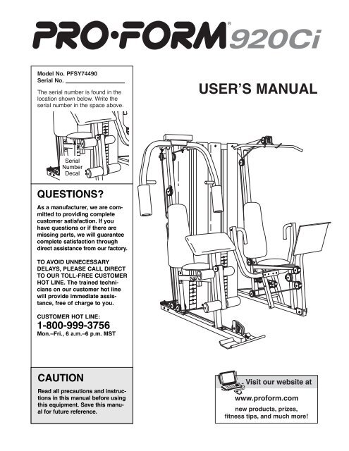
¨Model No. PFSY74490Serial No.The serial number is found in thelocation shown below. Write theserial number in the space above.USERÕS MANUALSerialNumberDecalQUESTIONS?As a manufacturer, we are committedto providing completecustomer satisfaction. If youhave questions or if there aremissing parts, we will guaranteecomplete satisfaction throughdirect assistance from our factory.TO AVOID UNNECESSARYDELAYS, PLEASE CALL DIRECTTO OUR TOLL-FREE CUSTOMERHOT LINE. The trained technicianson our customer hot linewill provide immediate assistance,free of charge to you.CUSTOMER HOT LINE:1-800-999-3756Mon.ÐFri., 6 a.m.Ð6 p.m. MSTCAUTIONRead all precautions and instructionsin this manual before usingthis equipment. Save this manualfor future reference.Visit our website atwww.<strong>proform</strong>.comnew products, prizes,fitness tips, and much more!
Table of ContentsImportant Precautions . . . . . . . . . . . . . . . . . . . . . . . . . . . . . . . . . . . . . . . . . . . . . . . . . . . . . . . . . . . . . . . . . . . 2Before You Begin . . . . . . . . . . . . . . . . . . . . . . . . . . . . . . . . . . . . . . . . . . . . . . . . . . . . . . . . . . . . . . . . . . . . . . 3Assembly . . . . . . . . . . . . . . . . . . . . . . . . . . . . . . . . . . . . . . . . . . . . . . . . . . . . . . . . . . . . . . . . . . . . . . . . . . . . 4Cable Diagrams . . . . . . . . . . . . . . . . . . . . . . . . . . . . . . . . . . . . . . . . . . . . . . . . . . . . . . . . . . . . . . . . . . . . . . 22Adjustment . . . . . . . . . . . . . . . . . . . . . . . . . . . . . . . . . . . . . . . . . . . . . . . . . . . . . . . . . . . . . . . . . . . . . . . . . . 24Trouble-shooting and Maintenance . . . . . . . . . . . . . . . . . . . . . . . . . . . . . . . . . . . . . . . . . . . . . . . . . . . . . . . . 25Weight Resistance Chart . . . . . . . . . . . . . . . . . . . . . . . . . . . . . . . . . . . . . . . . . . . . . . . . . . . . . . . . . . . . . . . . 27Ordering Replacement Parts . . . . . . . . . . . . . . . . . . . . . . . . . . . . . . . . . . . . . . . . . . . . . . . . . . . . . . Back CoverLimited Warranty . . . . . . . . . . . . . . . . . . . . . . . . . . . . . . . . . . . . . . . . . . . . . . . . . . . . . . . . . . . . . . . Back CoverNote: A PART LIST/EXPLODED DRAWING and a PART IDENTIFICATION CHART are attached in the center ofthis manual.Important PrecautionsWARNING: To reduce the risk of serious injury, read the following important precautionsbefore using the home gym.1. It is the responsibility of the owner to ensurethat all users of the home gym are adequatelyinformed of all precautions.2. Read all instructions in this manual and inthe accompanying literature before using thehome gym.3. If you feel pain or dizziness while exercising,stop immediately and begin cooling down.4. Use the home gym only on a level surface.Cover the floor or carpet beneath the homegym for protection.5. Inspect and tighten all parts often. Replaceany worn parts immediately.6. Make sure that the cables remain on the pulleysat all times. If the cables bind while youare exercising, stop immediately and makesure that the cables are on all of the pulleys.7. Always stand on the foot plate when doing anexercise that could cause the home gym to tip.8. Keep hands and feet away from moving parts.9. Keep children under the age of 12 and petsaway from the home gym at all times.10. Always wear athletic shoes for foot protectionwhen exercising.11. Never release the press arms, butterfly arms,leg lever, lat bar, or ab strap while weights areraised. The weights will fall with great force.12. Always disconnect the lat bar or ab strapfrom the home gym when performing anexercise that does not use these attachments.13. The home gym is intended for home use only.Do not use the home gym in a commercial,rental or institutional setting.14. The decal shown atthe right has beenplaced on the homegym in the twolocations shown onpage 3. If a decal ismissing or illegible,please call the customerhotline listedon the front coverof this manual toorder a freereplacement decal.Apply the decal inthe location shown.WARNING: Before beginning this or any exercise program, consult your physician. This is especiallyimportant for persons over the age of 35 or persons with pre-existing health problems. Read allinstructions before using. ICON assumes no responsibility for personal injury or property damagesustained by or through the use of this product.2
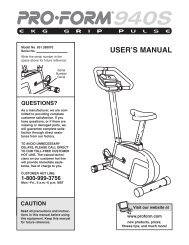
Before You BeginThank you for selecting the versatile PROFORM¨920Ci home gym. The PROFORM¨ 920Ci offers awide selection of weight stations designed to developevery major muscle group of the body. Whether yourgoal is to tone your body, build dramatic muscle sizeand strength, or improve your cardiovascular system,the PROFORM¨ 920Ci will help you to achieve theresults you want.For your benefit, read this manual carefully beforeusing the PROFORM¨ 920Ci home gym. If you haveadditional questions, please call our Customer ServiceDepartment toll-free at 1-800-999-3756, Mondaythrough Friday, 6 a.m. until 6 p.m. Mountain Time(excluding holidays). To help us assist you, please notethe product model number and serial number beforecalling. The model number is PFSY74490. The serialnumber can be found on a decal attached to the PRO-FORM¨ 920Ci (see the front cover of this manual).Before reading further, please familiarize yourself withthe parts that are labeled in the drawing below.Lat BarHighPulleyStationButterflyArmsShroudWARNINGDECALWARNINGDECALBackrestPress ArmsCurl PadSeatPress PlateWeight StackLow PulleyStationASSEMBLEDDIMENSIONS:Height: 75 in.Width: 78 in.Depth: 58.5 in.3
Frame Assembly1. Before beginning, make sure that you have readand understood the information on page 4.14282828Open the parts bag labeled ÒFRAME ASSEMBLY.Ó85Press a 2Ó Square Inner Cap (28) into each end ofthe Butterfly Base (4) and into the indicated bracketson the Weight Base (5).Insert four 5/16Ó x 2 1/2Ó Carriage Bolts (92) and a3/8Ó x 3 3/4Ó Carriage Bolt (85) up through the indicatedholes in the Butterfly Base (4). Note: If the Boltsfall out, secure them by putting a piece of tapeover the head of each Bolt. Place the Butterfly Baseflat on the floor.28289929252. Attach the Weight Base (5) to the Butterfly Base (4)with two 5/16Ó x 2 3/4Ó Bolts (89), a Support Plate(94), and two 5/16Ó Nylon Locknuts (64).946446453. Press a 2Ó Square Inner Cap (28) into each end ofthe Press Base (6).3Insert four 5/16Ó x 2 1/2Ó Carriage Bolts (92) and a3/8Ó x 4Ó Carriage Bolt (104) up through the indicatedholes in the Press Base (6).6282892104924. Attach the Press Base (6) to the Weight Base (5) withtwo 5/16Ó x 2 3/4Ó Bolts (89), a Support Plate (94),and two 5/16Ó Nylon Locknuts (64).456464946895
5. Place the bracket on the lower end of the PressUpright (2) over the indicated 5/16Ó x 2 1/2Ó CarriageBolts (92) in the Press Base (6). Hand tighten two5/16Ó Nylon Locknuts (64) onto the Bolts. Do nottighten the Nylon Locknuts yet.52649266. Place the bracket on the lower end of the ButterflyUpright (1) over the indicated 5/16Ó x 2 1/2Ó CarriageBolts (92) in the Butterfly Base (4). Hand tighten two5/16Ó Nylon Locknuts (64) onto the Bolts. Do nottighten the Nylon Locknuts yet.61644927. Place two Weight Bumpers (51) over the indicatedholes in the Weight Base (5). Slide a Weight Guide(15) into each of the holes.Attach the indicated Weight Guide (15) to the WeightBase (5) with a 3/8Ó x 2 3/4Ó Bolt (46), two 3/8Ó FlatWashers (48), and a 3/8Ó Nylon Locknut (50). Note:When attaching the Weight Guides to the WeightBase, make sure that the tops of both WeightGuides are in back of the weight top frame asshown in step 12.7GroovePin15171816Slide six Weights (21) onto the Weight Guides (15).Make sure the Weights are turned so the pingrooves point towards the floor.PinGrooves21Identify the Short Weight Tube (17), which has sixholes in it. Press a Weight Tube Bumper (18) into thelower end of the Short Weight Tube. Slide the WeightTube into the Weights (21).5150Slide a Top Weight (16) onto the Weight Guides (15).Make sure the Top Weight is turned so the groovefits over the welded pin on the Short Weight Tube(17).46548486
8. Place two Weight Bumpers (51) over the indicatedholes in the Weight Base (5). Slide a Weight Guide(15) into each of the holes.816Attach the indicated Weight Guide (15) to the WeightBase (5) with a 3/8Ó x 2 3/4Ó Bolt (46), two 3/8Ó FlatWashers (48), and a 3/8Ó Nylon Locknut (50).15Slide twelve Weights (21) onto the Weight Guides(15). Make sure the Weights are turned so the pingrooves point towards the floor.Identify the Long Weight Tube (96), which has twelveholes in it. Press a Weight Tube Bumper (18) into thelower end of the Long Weight Tube. Slide the WeightTube into the Weights (21).1896HoleSlide a Top Weight (16) onto the Weight Guides (15).Make sure the Top Weight is turned so the groovefits over the welded pin on the Long Weight Tube(96).51214654848509. Place the Weight Top Frame (66) on the indicatedbrackets on the Uprights (1, 2).Attach the Weight Top Frame (66) to each Upright (1,2) with two 3/8Ó x 2 3/4Ó Bolts (46), a Small SupportPlate (26), and two 3/8Ó Nylon Locknuts (50).Tighten all of the Nylon Locknuts used in steps 5to 7.94626506646261Brackets50210. Press three 2Ó Square Inner Caps (28) into theButterfly Top Frame (33).1089Attach the Butterfly Top Frame (33) to the indicatedbrackets at the top of the Butterfly Upright (1) and atthe end of the Weight Top Frame (66) with four 5/16Óx 2 3/4Ó Bolts (89), two Support Plates (94), and four5/16Ó Nylon Locknuts (64).2833899494286466286417
11. Press a 2Ó Square Inner Cap (28) into each end ofthe Press Top Frame (9).1164Attach the Press Top Frame (9) to the indicatedbracket at the top of the Press Upright (2) and at theend of the Weight Top Frame (66) with four 5/16Ó x2 3/4Ó Bolts (89), two Support Plates (94), and four5/16Ó Nylon Locknuts (64).66264899494289892812. Attach the Weight Guides (15) to the Weight TopFrame (66) with four 3/8Ó x 3 3/4Ó Bolts (59), four 3/8ÓFlat Washers (48), and four 3/8Ó Nylon Locknuts (50).Do not overtighten the Nylon Locknuts.1248506648505915921513. Attach the Butterfly Seat Frame (14) to the ButterflyUpright (1) with two 5/16Ó x 2 3/4Ó Bolts (89), two5/16Ó Washers (36), and two 5/16Ó Nylon Locknuts(64). Do not tighten the Nylon Locknuts yet.131418936648
14. Press a 2Ó Square Inner Cap (28) into the ButterflyFront Leg (3). Slide the bracket on the Butterfly FrontLeg onto the two indicated 5/16Ó x 2 1/2Ó CarriageBolts (92) in the Butterfly Base (4). Hand tighten two5/16Ó Nylon Locknuts (64) onto the Bolts. Do nottighten the Nylon Locknuts yet.148936286414Attach the Butterfly Front Leg (3) to the Butterfly SeatFrame (14) with two 5/16Ó x 2 3/4Ó Bolts (89), two5/16Ó Washers (36), and two 5/16Ó Nylon Locknuts(64). Tighten all of the Nylon Locknuts used insteps 13 and 14.3646449215. Press a 2Ó Square Inner Cap (28) into the Press SeatFrame (7).158936Slide the bracket on the Press Seat Frame (7) ontothe indicated 5/16Ó x 2 1/2Ó Carriage Bolts (92) in thePress Base (6). Hand tighten two 5/16Ó NylonLocknuts (64) onto the Bolts. Do not tighten theNylon Locknuts yet.Attach the Press Seat Frame (7) to the Press Upright(2) with two 5/16Ó x 2 3/4Ó Bolts (89), two 5/16ÓWashers (36), and two 5/16Ó Nylon Locknuts (64).2864789626436Tighten all of the Nylon Locknuts used in thisstep.9216. Press two 2Ó Square Inner Caps (28) into both endsof the Leg Lever (41). Attach the Bumper (40) to theindicated hole in the Butterfly Front Leg (3) with a 1ÓTap Screw (80).162863Lubricate the 3/8Ó x 3 1/4Ó Bolt (62). Attach the LegLever (41) to the Butterfly Front Leg (3) with the Boltand a 3/8Ó Nylon Jam Nut (63). Do not overtightenthe Nylon Jam Nut; the Leg Lever must pivotfreely.2841804036217. Position the Press Front Leg (20) with the welded rodfacing forward as shown. Press a 2Ó x 4Ó Inner Cap(98) into the indicated end of the Press Front Leg(20).Attach the Press Front Leg (20) to the Press Base (6)with a 1/2Ó x 3 1/2Ó Bolt (105) and a 1/2Ó Nylon JamNut (106). Do not overtighten the Nylon Jam Nut;the Press Front Leg must pivot freely.17Weldedrod9820106 61059
Arm Assembly1818. Open the parts bag labeled ÒARM ASSEMBLY.ÓPress a Plastic Bushing (100) onto each welded tubeon the Press Frame (8).50Lubricate the 3/8Ó x 9Ó Bolt (52). Attach the PressFrame (8) to the welded tubes on the Press Base (6)with the Bolt and a 3/8Ó Nylon Locknut (50). Do notovertighten the Nylon Locknut; it must be easy topivot the Press Frame.610052819. Press a 2Ó Square Inner Cap (28) into the top of aPress Arm (77).Press a 1Ó Inner Cap (76) into the indicated hole inthe Press Arm (77).1928Attach the Press Arm (77) to the bracket on the PressFrame (8) with two 5/16Ó x 2 3/4Ó Bolts (89) and two5/16Ó Nylon Locknuts (64).647776Repeat this step to assemble the other Press Arm(77, not shown).88920. Press a 2Ó Square Inner Cap (28) into each end ofthe Right Butterfly Arm (11). Wet the lower end of theArm with soapy water. Slide a Butterfly Foam Pad(29) onto the lower end of the Arm.2033Lubricate the indicated axle on the Butterfly TopFrame (33). Orient the Right Butterfly Arm (11) asshown and slide it onto the axle. Secure the ButterflyArm with two Retainer Rings (31) and a 1Ó RoundOuter Cap (38). Note: Place the Retainer Rings ontop of the inverted Outer Cap and gently tap theCap onto the axle with a hammer. Make sure theteeth on the Retainer Rings bend towards the Capas shown in the inset drawing.Repeat this step to assemble the Left Butterfly Arm(10, not shown).1131282938Lubricate28Axle31Teeth3810
Cable Assembly21. Open the parts bag labeled ÒCABLE ASSEMBLYAND PULLEYS.Ó For Cable identification and routingduring steps 21 to 52, refer to the CableDiagram and Cable ID Chart on pages 22 and 23.21Bracket8463Important: Although the following steps are notdifficult to perform, the correct routing of thecable is critical to the functioning of the homegym. Please make sure that you wrap the cablearound the pulleys exactly as shown in each step.7310Identify the Butterfly Cable (73); it is approximately72Ó long and it has a loop on each end. Attach oneend of the Butterfly Cable to the bracket on the LeftButterfly Arm (10) with a 3/8Ó x 1Ó Bolt (84) and two3/8Ó Nylon Jam Nuts (63). Note: The loop on theCable and the two Nylon Jam Nuts must beunderneath the bracket. Do not overtighten thebottom Nylon Jam Nut; the Cable must pivotfreely on the Bolt.22Bracket502732 537322. Wrap the Butterfly Cable (73) around a ÒVÓ-Pulley(27) in the direction shown. Attach the ÒVÓ-Pulley anda Large Cable Trap (32) to the bracket on the backof the Butterfly Upright (1) with a 3/8Ó x 2 1/2Ó Bolt(53) and a 3/8Ó Nylon Locknut (50). Make sure thatthe Large Cable Trap is oriented as shown.123. Remove both 3 1/2Ó Pulleys (24) and the Cable Traps(25) from one pair of pre-assembled Pulley Plates(23).2373Wrap the Butterfly Cable (73) around a 3 1/2Ó Pulley(24) in the direction shown. Attach the Pulley and theCable Trap (25) to the top hole in the Pulley Plates(23) with a 3/8Ó x 2Ó Bolt (54) and a 3/8Ó NylonLocknut (50). Make sure the Cable Trap and PulleyPlates are oriented as shown in the drawing. 542425235024. Wrap the Butterfly Cable (73) around a ÒVÓ-Pulley(27) in the direction shown. Attach the ÒVÓ-Pulley anda Large Cable Trap (32) to the welded bracket (seethe inset drawing) on the back of the ButterflyUpright (1) with a 3/8Ó x 2 1/2Ó Bolt (53) and a 3/8ÓNylon Locknut (50). Make sure that the Large CableTrap is oriented as shown.2453733227Weldedbracket50Weldedbracket111
25. Attach the Butterfly Cable (73) to the bracket on theRight Butterfly Arm (11) with a 3/8Ó x 1Ó Bolt (84) andtwo 3/8Ó Nylon Jam Nuts (63). Note: The loop onthe Cable and the two Nylon Jam Nuts must beunderneath the bracket. Do not overtighten thebottom Nylon Jam Nut; the Cable must pivotfreely on the Bolt.251184637326. Identify the Ab Cable (74). It is approximately 234.3/4Ó long, and it has a ball on one end and a threadedshaft on the other. You will start by attaching the endof the Cable with the ball.Wrap the Ab Cable (74) around a 3 1/2Ó Pulley (24) inthe direction shown. Place two Pulley Covers (47)over the Pulley, so that the slots in the Pulley Coversare placed over the Cable. Attach the Pulley andPulley Covers to the indicated hole in the ButterflyUpright (1) with a 3/8Ó x 3 3/4Ó Bolt (59), two 3/8Ó FlatWashers (48), and a 3/8Ó Nylon Jam Nut (63). Makesure the Cable is between the Pulley and thewelded pin on the Upright.266348472474Weldedpin147485927. Remove both 3 1/2Ó Pulleys (24) from the pre-assembledPulley Plates (23).27PulleyWrap the Ab Cable (74) around a 3 1/2Ó Pulley (24) inthe direction shown. Attach the Pulley and a CableTrap (25) to the top hole in the two Pulley Plates (23)with a 3/8Ó x 2Ó Bolt (54) and a 3/8Ó Nylon Locknut(50). Make sure the Cable Trap and the PulleyPlates are oriented as shown.5424742550Route the Ab Cable (74) up through the pulley on theButterfly Upright (1) from below.23128. Wrap the Ab Cable (74) around a 3 1/2Ó Pulley (24) inthe direction shown. Attach the Pulley and a CableTrap (25) to the indicated hole in the Pulley Plates(23) with a 3/8Ó x 2Ó Bolt (54) and a 3/8Ó NylonLocknut (50). Make sure that the Pulley Bracketand Cable Trap are oriented exactly as shown.2812374 502354242512
29. Wrap the Ab Cable (74) around a 3 1/2Ó Pulley (24) inthe direction shown. Attach the Pulley and a CableTrap (25) to the welded bracket on the Butterfly Base(4) with a 3/8Ó x 2Ó Bolt (54) and a 3/8Ó Nylon Locknut(50).2974245425504Weldedbracket30. Wrap the Ab Cable (74) around a 3 1/2Ó Pulley (24) inthe direction shown. Slide the Pulley and a CableTrap (25) onto the 3/8Ó x 3 3/4Ó Carriage Bolt (85) thatwas inserted into the Butterfly Base (4) earlier.Secure the Pulley with a 3/8Ó Nylon Jam Nut (63).Make sure the Cable Trap is oriented as shown.302463748525431. Wrap the Ab Cable (74) around a 3 1/2Ó Pulley (24) inthe direction shown. Attach the Pulley to the bracketon the Weight Base (5) with a 3/8Ó x 1 3/4Ó Bolt (57)and a 3/8Ó Nylon Locknut (50).3174245057532. Wrap the Ab Cable (74) around a 4 1/2Ó Pulley (102)in the direction shown. Attach the Pulley inside theindicated bracket on the Weight Top Frame (66) witha 3/8Ó x 2Ó Bolt (54) and a 3/8Ó Nylon Locknut (50).Make sure the threaded end of the High Cable isrouted through the bracket.32Bracket501025474 6613
33. Attach the threaded end of the Ab Cable (74) to aÒUÓ-Bracket (97) with a 1/4Ó Flat Washer (71) and a1/4Ó Nylon Locknut (68). Note: Do not completelytighten the Nylon Locknut; it should be threadedonly two turns onto the end of the Cable, asshown in the inset drawing.Attach the ÒUÓ-Bracket (97) to the hole in the ShortWeight Tube (17) with a 5/16Ó x 1 3/4Ó Bolt (60) and a5/16Ó Nylon Locknut (64).33747160177464977168689734. Identify the Low Cable (75). It is approximately 123.1/4Ó long and it has a ball on one end and a loop onthe other. Route the end with the loop through the slotin the cable guide on the Butterfly Base (4).Route the Low Cable (75) under a 3 1/2Ó Pulley (24)as shown. Attach the Pulley and a Cable Trap (25) tothe bracket on the Butterfly Base (4) with a 3/8Ó x 2ÓBolt (54) and a 3/8Ó Nylon Locknut (50). Make surethe Cable Trap is oriented as shown.34454CableGuide2575245035. Wrap the Low Cable (75) around a 3 1/2Ó Pulley (24)in the direction shown.35175Attach two Pulleys (24) and two Cable Traps (25) tothe Butterfly Upright (1) with a 3/8Ó x 5Ó Bolt (108)and a hand tightened 3/8Ó Nylon Locknut (50) asshown. Do not tighten the Nylon Locknut beforestep 37.502425252410836. Wrap the Low Cable (75) over a 3 1/2Ó Pulley (24) inthe direction shown. Attach the Pulley and a CableTrap (25) to the lower hole in the Pulley Plates (23)with a 3/8Ó x 2Ó Bolt (54) and a 3/8Ó Nylon Locknut(50). Make sure the Cable Trap is oriented asshown.3675232450255414
37. Remove the 3/8Ó Nylon Locknut (50) and 3 1/2Ó Pulley(24). Wrap the Low Cable (75) around the Pulley inthe direction shown. Reattach the Pulley and tightenthe Nylon Locknut. Make sure the Cable is routedexactly as shown.3775502438. Attach the loop on the end of the Low Cable (75) tothe indicated hole in the Leg Lever (41) with a 3/8Ó x2 3/4Ó Bolt (46), two 3/8Ó Flat Washers (48), and a3/8Ó Nylon Locknut (50). Do not overtighten theNylon LockNut; the Cable must pivot freely on theBolt.3846417548504839. Identify the High Cable (72). It is approximately 369Ólong and it has a ball on one end and a threadedshaft on the other. You will begin by attaching the endwith the ball.3924Wrap the High Cable (72) around a 3 1/2Ó Pulley (24)in the direction shown. Attach the Pulley to the indicatedhole in the Press Top Frame (9) with a 3/8Ó x 31/2Ó Bolt (56), a 3/8Ó Flat Washer (48), and a 3/8ÓNylon Jam Nut (63).56724896340. Wrap the High Cable (72) around a 3 1/2Ó Pulley (24)in the direction shown. Attach the Pulley to the indicatedhole in the Press Upright (2) with a 3/8Ó x 3 3/4ÓBolt (59), a 3/8Ó Flat Washer (48), and a 3/8Ó NylonJam Nut (63).40726324254859215
41. Wrap the High Cable (72) around a 3 1/2Ó Pulley (24)41in the direction shown. Attach the Pulley to the indicatedhole in the Press Upright (2) with a 3/8Ó x 3 3/4ÓBolt (59), a 3/8Ó Flat Washer (48), and a 3/8Ó Nylon5924Jam Nut (63). Make sure the Cable Trap is orientedas shown. 27225634842. Wrap the High Cable (72) around a 3 1/2Ó Pulley (24)in the direction shown. Attach the Pulley and a CableTrap (25) to the indicated hole in the Press Front Leg(20) with a 3/8Ó x 3 3/4Ó Bolt (59), a 3/8Ó Flat Washer(48), and a 3/8Ó Nylon Jam Nut (63).427259242025486343. Wrap the High Cable (72) around a 3 1/2Ó Pulley (24)in the direction shown. See the inset drawing. Makesure the Cable is routed exactly as shown.Attach the Pulley (24) and a Cable Trap (25) to theindicated hole on the far side of the Press SeatFrame (7) with a 3/8Ó x 3 3/4Ó Bolt (59), a 3/8Ó FlatWasher (48) and a 3/8Ó Nylon Jam Nut (63).4359722425486372444. Wrap the High Cable (72) around a 3 1/2Ó Pulley (24)in the direction shown. See the inset drawing. Makesure the Cable is routed exactly as shown. Attachthe Pulley and a Cable Trap (25) to the Press FrontLeg (20) with a 3/8Ó x 3 3/4Ó Bolt (59), a 3/8Ó FlatWasher (48) and a 3/8Ó Nylon Jam Nut (63).447224594824 25 632016
45. Wrap the High Cable (72) around a 3 1/2Ó Pulley (24)in the direction shown. Attach the Pulley and a CableTrap (25) to the indicated hole in the Press Upright(2) with a 3/8Ó x 3 3/4Ó Bolt (59), a 3/8Ó Flat Washer(48), and a 3/8Ó Nylon Jam Nut (63). Make sure thatthe Cable Trap is oriented as shown and that theCable is routed through the center of the PressUpright.17
49. Wrap the High Cable (72) around a 3 1/2Ó Pulley (24)in the direction shown. Attach the Pulley, a CableTrap (25), and an Angle Spacer (103) to the 3/8Ó x 4ÓCarriage Bolt (104) that was inserted into the PressBase (6) earlier. Make sure the Angle Spacer isangled exactly as shown. Secure the Pulley with a3/8Ó Nylon Jam Nut (63). Make sure the Cable Trapis oriented as shown.4963242572103650. Wrap the High Cable (72) around a 3 1/2Ó Pulley (24)in the direction shown. Attach the Pulley to the indicatedbracket on the Weight Base (5) with a 3/8Ó x 13/4Ó Bolt (57) and a 3/8Ó Nylon Locknut (50). Makesure that the Cable Trap is oriented as shown.5024507257551. Wrap the High Cable (72) over a 4 1/2Ó Pulley (102)in the direction shown. Attach the Pulley inside theindicated bracket on the Weight Top Frame (66) witha 3/8Ó x 2Ó Bolt (54) and a 3/8Ó Nylon Locknut (50).Make sure the end of the Cable is routed downthrough the bracket.5166Bracket50102547252. Attach the threaded end of the High Cable (72) to theremaining ÒUÓ-Bracket (97) with a 1/4Ó Flat Washer(71) and a 1/4Ó Nylon Locknut (68). Note: Do notcompletely tighten the Nylon Locknut; it shouldbe threaded only two turns onto the end of theCable, as shown in the inset drawing.52729764Attach the ÒUÓ-Bracket (97) to the hole in the LongWeight Tube (96) with a 5/16Ó x 1 3/4Ó Bolt (60) and a5/16Ó Nylon Locknut (64).Important: Follow all four cables from end to endand make sure that they rest in the grooves of allof the pulleys and that the cables and the pulleysmove smoothly.727168976071689618
60. Remove the pre-assembled 1/4Ó x 5/8Ó Screws (95)from the Weight Base (5). Attach the Right and LeftShrouds (34, 109) to the brackets on the Weight Base(5) with two 1/4Ó x 5/8Ó Screws (95).Attach the other set of shrouds (not shown) on theother weight stack exactly as explained in steps 59and 60.603410959561. Attach the Press Plate (55) to the Press Front Leg(20) by securing it with the Lock Pin (22). Note: Thelip on the Press Plate must be on the upper edge.6122See the inset drawing. Be sure that the Lock Pin(22) is positioned as shown.5520552262. Make sure that all parts are properly tightened. The use of the remaining parts will be explained in ADJUST-MENT, beginning on page 24 of this manual.Before using the home gym, pull each cable a few times to make sure that the cables move smoothly overthe pulleys. If one of the cables does not move smoothly, find and correct the problem. IMPORTANT: If thecables are not properly installed, they may be damaged when heavy weight is used. If there is anyslack in the cables, you will need to remove the slack by tightening the cables. See TROUBLE-SHOOTING AND MAINTENANCE on page 25.21
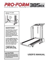
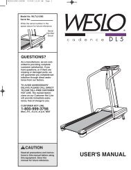
Cable DiagramsThe cable diagrams below and on the next page show the proper routing of the Butterfly Cable (73), the AbCable (74), the Low Cable (75), and the High Cable (72). The numbers show the correct route for each Cable.Make sure that the Cables are routed correctly, that the pulleys move smoothly, and that the cable trapsdo not touch or bind the Cables. Incorrect cable routing can damage the weight system.Butterfly Cable (73)5412Low Cable (75)33Ab Cable (74)75142123Cable ID Chart(73)Ñ72Ó58(75)Ñ123. 1/4Ó46(74)Ñ234. 3/4Ó(72)Ñ369Ó22
High Cable (72)131214312109486571123
AdjustmentThe instructions below describe how each part of the home gym can be adjusted. Refer to the exercise guideaccompanying this manual to see how the home gym should be set up for each exercise. IMPORTANT: Whenusing an attachment, make sure it is in the correct starting position for the exercise to be performed. Ifthere is any slack in the cables or chain as an exercise is performed, the effectiveness of the exercisewill be reduced.Attaching the Lat Bar, Row Bar, Nylon Strap, or AbStrap to the Low Pulley Station, the High PulleyStation, or the Ab Pulley Station.Attach the Lat Bar (61) to the Low Cable (75) with aCable Clip (69). For some exercises, the Chain (67)should be attached between the Lat Bar and the LowCable with two Cable Clips. Adjust the length of theChain between the Lat Bar and the Low Cable so theLat Bar is in the correct starting position for the exerciseto be performed.445867The Row Bar (44), Nylon Strap (58), or Ab Strap (81) canbe attached in the same manner.6975Use the same method for attaching any of the attachmentsto the High Cable (74, not shown) at the high pulleystation or the ab pulley station.616981Adjusting the Butterfly Backrest, Butterfly Seat, orPress BackrestTo adjust the Press Backrest (99), loosen the AdjustmentKnob (78) by turning it counterclockwise. Slide theBackrest in or out as needed. Release the AdjustmentKnob and let the pin on the Knob snap into one of theholes in the Press Upright (2). Retighten the Knob byturning it clockwise.29978Changing the Weight SettingTo change the setting of either weight stack, insert aWeight Pin (19) under the desired Weight (21). Make sureyou insert the Weight Pin as far as it will go. Note: Due tothe cables and pulleys, the amount of resistance ateach exercise station may vary from the weight setting.Use the WEIGHT RESISTANCE CHART on page26 to find the approximate amount of resistance ateach weight station.192124
Adjusting the Press PlateRemove the Lock Pin (22) from the Press Plate (55) andthe Press Front Leg (20).22Align the holes in the Press Plate (55) with the desiredset of holes in the Press Front Leg (20). Re-insert theLock Pin (22) through the welded tube on the Press FrontLeg and the holes in the Press Plate.5520Trouble-shooting and MaintenanceInspect and tighten all parts each time you use the home gym. Replace any worn parts immediately. The homegym can be cleaned using a damp cloth and mild non-abrasive detergent. Do not use solvents.Tightening the CablesWoven cable, the type of cable used on the home gym,can stretch slightly when it is first used. If there is slack inthe cables before resistance is felt, the cables should betightened. Slack can be removed from the cables in severaldifferent ways:The 3 1/2Ó Pulley (24) is located under the Press SeatFrame (7). There are four adjustment holes in the PressSeat Frame. By moving the Pulley closer to the PressUpright (2), you will tighten the cables. By moving it furtheraway from the Upright, you will loosen the cable. Seeassembly step 47 for instructions on how to remove thePulley assembly.The Pulley Plates (23) have two sets of adjustment holes.By moving one or both pulleys to a different set of holes,the cables will be tightened.7242To move a Pulley, remove the 3/8Ó Nylon Locknut (50)and the 3/8Ó x 2Ó Bolt (54). Remove the Cable Trap (25)and the Pulley (24) from the Pulley Plates (23). Re-attachthe Pulley and the Cable Trap to the appropriate hole inthe Pulley Plates. Note: Begin by moving one Pulley. Ifthe Cables are still too loose, move the other Pulleyuntil the Cables are tight.5423Adjustmentholes50252425
The threaded ends on the High Cable (72) and the AbCable (74) that are attached to the weight stacks can alsobe used to tighten the cables.To tighten the Cables (72, 74), remove the ÒUÓ-Bracket(97) from the weight tube by removing the 5/16Ó x 1 3/4ÓBolt (60) and the 5/16Ó Nylon Locknut (64).Tighten the 1/4Ó Nylon Locknut (68) at the end of theCables (72, 74) as far as it will go. Then re-attach the ÒUÓ-Bracket (97).Note: The shrouds are shown removed for clarity. Theshrouds do not need to be removed to tighten thecables.Note: If a cable tends to slip off the pulleys often, thecable may have become twisted. Remove the cableand re-install it.If the cables need to be replaced, see ORDERINGREPLACEMENT PARTS on the back cover of this manual.Bolt6097727464716826
Weight Resistance ChartThe chart below shows the approximate weight resistance at each exercise station. ÒTopÓ refers to the 6 lb. topweight; the other numbers refer to the 10 lb. weight plates. Note: The actual resistance at each station mayvary due to differences in individual weight plates as well as friction between the cables, pulleys, andweight guides.WEIGHT HIGH LEG LEG ARM BUTTERFLY AB LOWPULLEY RAISE PRESS PRESS ARMS STATION PULLEYPLATES (lbs.) (lbs.) (lbs.) (lbs.) (lbs.) (lbs.) (lbs.)TOP 17 18 23 8 11 14 111 31 34 55 22 25 28 242 45 50 88 37 39 42 383 59 66 120 51 52 56 514 73 82 152 66 66 69 645 87 97 185 80 80 83 786 101 113 217 95 93 97 917 115 250 1098 129 282 1249 143 314 13810 157 347 15311 171 379 16712 185 411 18227
Retainer Ring (31)1" Inner Cap (76)3/4" Round Inner Cap (43)1" Round Outer Cap (38)1Ó x 2" Inner Cap (83)1 1/4" Square Inner Cap (35)2" Square Inner Cap (28)
Part Identification ChartÑModel No. PFSY74490R1199A5/16" Washer (36)3/8" Flat Washer (48)1/2" Nyoln Jam Nut (106 )1Ó Tap Screw (80)1/4" Flat Washer (71)3/8" Nylon Jam Nut (63)1/4" x 3/4" Bolt (49)1/4" Nylon Locknut (68)3/8" Nylon Locknut (50)1/4" x 5/8" Screw (95)5/16" Nylon Locknut (64)1/2" x 3 1/2" Bolt (105)1/4" x 1 1/2" Carriage Bolt (101) 1/4" x 1 1/2" Bolt (82)1/4" x 2 1/2" Bolt (79)1/4" x 2 1/2" Carriage Bolt (45)5/16" x 2 3/4" Bolt (89) 5/16" x 2 1/2" Carriage Bolt (92)
3/8" x 9" Bolt (52)3/8" x 5" Bolt (108)3/8" x 4" Carriage Bolt (102)3/8" x 1 3/4" Bolt (57)5/16" x 1 3/4" Bolt (60)3/8" x 2" Bolt (54)3/8" x 2 1/2" Bolt (53)3/8" x 2 3/4" Bolt (46)3/8" x 1" Bolt (84)3/8" x 3 1/4" Bolt (62)3/8" x 3 1/2" Bolt (56)3/8" x 3 3/4" Carriage Bolt (85)3/8" x 3 3/4" Bolt (59)
Part ListÑModel No. PFSY74490R1199AKey No. Qty. Description Key No. Qty. Description1 1 Butterfly Upright2 1 Press Upright3 1 Butterfly Front Leg4 1 Butterfly Base5 1 Weight Base6 1 Press Base7 1 Press Seat Frame8 1 Press Frame9 1 Press Top Frame10 1 Left Butterfly Arm11 1 Right Butterfly Arm12 1 Butterfly Backrest13 2 Seat14 1 Butterfly Seat Frame15 4 Weight Guide16 2 Top Weight17 1 Short Weight Tube18 2 Weight Tube Bumper19 2 Weight Pin20 1 Press Front Leg21 18 Weight22 1 Lock Pin23 4 Pulley Plate24 23 3 1/2Ó Pulley25 19 Cable Trap26 2 Small Support Plate27 2 ÒVÓ-Pulley28 21 2Ó Square Inner Cap29 2 Butterfly Foam Pad30 4 Foam Pad31 4 Retainer Ring32 2 Large Cable Trap33 1 Butterfly Top Frame34 2 Right Shroud35 3 1 1/4Ó Square Inner Cap36 6 5/16Ó Washer37 2 Butterfly Arm Bushing38 2 1Ó Round Outer Cap39 4 Plastic Grip40 1 Bumper41 1 Leg Lever42 2 Pad Tube43 4 3/4Ó Round Inner Cap44 1 Row Bar45 1 1/4Ó x 2 1/2Ó Carriage Bolt46 7 3/8Ó x 2 3/4Ó Bolt47 2 Pulley Covers48 21 3/8Ó Flat Washer49 8 1/4Ó x 3/4Ó Bolt50 28 3/8Ó Nylon Locknut51 4 Weight Bumper52 1 3/8Ó x 9Ó Bolt53 2 3/8Ó x 2 1/2Ó Bolt54 9 3/8Ó x 2Ó Bolt55 1 Press Plate56 3 3/8Ó x 3 1/2Ó Bolt57 2 3/8Ó x 1 3/4Ó Bolt58 1 Nylon Strap59 11 3/8Ó x 3 3/4Ó Bolt60 2 5/16Ó x 1 3/4Ó Bolt61 1 Lat Bar62 1 3/8Ó x 3 1/4Ó Bolt63 15 3/8Ó Nylon Jam Nut64 32 5/16Ó Nylon Locknut65 3 Seat Plate66 1 Weight Top Frame67 1 Chain68 5 1/4Ó Nylon Locknut69 4 Cable Clip70 2 Backrest Adjustment Frame71 10 1/4Ó Flat Washer72 1 High Cable73 1 Butterfly Cable74 1 Ab Cable75 1 Low Cable76 2 1Ó Inner Cap77 2 Press Arm78 3 Adjustment Knob79 1 1/4Ó x 2 1/2Ó Bolt80 1 1Ó Tap Screw81 1 Ab Strap82 4 1/4Ó x 1 1/2Ó Bolt83 6 1Ó x 2Ó Inner Cap84 2 3/8Ó x 1Ó Bolt85 1 3/8Ó x 3 3/4Ó Carriage Bolt86 2 Small Grip87 2 Press Grip88 2 Butterfly Grip89 22 5/16Ó x 2 3/4Ó Bolt90 1 Seat Adjustment Frame91 1 Curl Pad92 8 5/16Ó x 2 1/2Ó Carriage Bolt93 1 Workout Decal94 6 Support Plate95 8 1/4Ó x 5/8Ó Screw96 1 Long Weight Tube97 2 ÒUÓ Bracket98 1 2Ó x 4Ó Inner Cap99 1 Press Backrest100 2 Plastic Bushing101 2 1/4Ó x 1 1/2Ó Carriage Bolt102 2 4 1/2Ó Pulley103 1 Angle Spacer104 1 3/8Ó x 4Ó Carriage Bolt105 1 1/2Ó x 3 1/2Ó Bolt106 1 1/2Ó Nylon Jam Nut107 1 Curl Post108 1 3/8Ó x 5Ó Bolt109 2 Left Shroud# 1 UserÕs ManualNote: Ò#Ó indicates a non-illustrated part. Specifications are subject to change without notice.
99592498485910610528922889252410463103922524591348632828505097211974606028899450248525246375549242524923030437550 63245024565250561006478641459363624 4774505024782489303043424364364037171358271828283717035128389283359 485964646464262610210254547628896477878789649595959581225483636646324 25 64507825242459594863242554505910728639898956 248686482894396139542324255023 24 25 718271358383651016870492248639328151896181672687164171668716415505051972119155153256448 150325053642727 3225474863292888882928847328371137847310313863313863255464645646457245724464848 485050464846506650461086744393955252524209466489897179 6874965452828504863284162482842434648 48825258089139083834965101689149542324255023 24 25 282894 892876776958643434109109Exploded DrawingÑModel No. PFSY74490R1199A
Ordering Replacement PartsTo order replacement parts, simply call our Customer Service Department toll-free at 1-800-999-3756, Mondaythrough Friday, 6 a.m. until 6 p.m. Mountain Time (excluding holidays). To help us assist you, please be preparedto give the following information:¥ The MODEL NUMBER of the product (PFSY74490)¥ The NAME of the product (PROFORM¨ 920Ci home gym)¥ The SERIAL NUMBER of the product (see the front cover of this manual)¥ The KEY NUMBER and DESCRIPTION of the part(s) (see the PART LIST and EXPLODED DRAWINGattached at the center of this manual).Limited WarrantyICON Health & <strong>Fitness</strong>, Inc. (ICON), warrants this product to be free from defects in workmanship and material,under normal use and service conditions, for a period of ninety (90) days from the date of purchase. Thiswarranty extends only to the original purchaser. ICON's obligation under this warranty is limited to replacingor repairing, at ICON's option, the product at one of its authorized service centers. All products for which warrantyclaim is made must be received by ICON at one of its authorized service centers with all freight andother transportation charges prepaid, accompanied by sufficient proof of purchase. All returns must be preauthorizedby ICON. This warranty does not extend to any product or damage to a product caused by orattributable to freight damage, abuse, misuse, improper or abnormal usage or repairs not provided by anICON authorized service center, products used for commercial or rental purposes, or products used as storedisplay models. No other warranty beyond that specifically set forth above is authorized by ICON.ICON is not responsible or liable for indirect, special or consequential damages arising out of or in connectionwith the use or performance of the product or damages with respect to any economic loss, loss of property,loss of revenues or profits, loss of enjoyment or use, costs of removal, installation or other consequentialdamages of whatsoever nature. Some states do not allow the exclusion or limitation of incidental or consequentialdamages. Accordingly, the above limitation may not apply to you.The warranty extended hereunder is in lieu of any and all other warranties and any implied warranties of merchantabilityor fitness for a particular purpose is limited in its scope and duration to the terms set forth herein.Some states do not allow limitations on how long an implied warranty lasts. Accordingly, the above limitationmay not apply to you.This warranty gives you specific legal rights. You may also have other rights which vary from state to state.ICON HEALTH & FITNESS, INC., 1500 S. 1000 W., LOGAN, UT 84321-9813PROFORM¨ is a registered trademark of ICON Health & <strong>Fitness</strong>, Inc.Part No. 159777 R1199APrinted in Canada © 1999 ICON Health & <strong>Fitness</strong>, Inc.