SACE Emax DC: Direct Current Applications - VAE ProSys sro
SACE Emax DC: Direct Current Applications - VAE ProSys sro
SACE Emax DC: Direct Current Applications - VAE ProSys sro

Create successful ePaper yourself
Turn your PDF publications into a flip-book with our unique Google optimized e-Paper software.
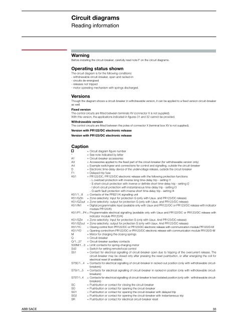
Circuit diagramsReading informationWarningBefore installing the circuit-breaker, carefully read note F on the circuit diagrams.Operating status shownThe circuit diagram is for the following conditions:- withdrawable circuit-breaker, open and racked-in- circuits de-energised- releases not tripped- motor operating mechanism with springs discharged.VersionsThough the diagram shows a circuit-breaker in withdrawable version, it can be applied to a fixed version circuit-breakeras well.Fixed versionThe control circuits are fitted between terminals XV (connector X is not supplied).With this version, the applications indicated in figures 31 and 32 cannot be provided.Withdrawable versionThe control circuits are fitted between the poles of connector X (terminal box XV is not supplied).Version with PR122/<strong>DC</strong> electronic releaseVersion with PR123/<strong>DC</strong> electronic releaseCaption= Circuit diagram figure number* = See note indicated by letterA1 = Circuit-breaker accessoriesA3 = Accessories applied to the fixed part of the circuit-breaker (for withdrawable version only)A4 = Example switchgear and connections for control and signalling, outside the circuit-breakerD = Electronic time-delay device of the undervoltage release, outside the circuit-breakerF1 = Delayed-trip fuseK51 = PR122/<strong>DC</strong>, PR123/<strong>DC</strong> electronic release with the following protection functions:- L overload protection with inverse long time-delay trip - setting I1- S short-circuit protection with inverse or definite short time-delay trip - setting I2- I short-circuit protection with instantaneous time-delay trip - setting I3- G earth fault protection with inverse short time-delay trip - setting I4K51/1...8 = Contacts of the PR021/K signalling unitK51/GZin = Zone selectivity: input for protection G (only with Uaux. and PR123/<strong>DC</strong> release)K51/GZout = Zone selectivity: output for protection G (only with Uaux. and PR123/<strong>DC</strong> release)K51/IN1 = Digital programmable input (available only with Uaux and PR122/<strong>DC</strong> or PR123/<strong>DC</strong> release with indicatormodule PR120/K)K51/P1...P4 = Programmable electrical signalling (available only with Uaux and PR122/<strong>DC</strong> or PR123/<strong>DC</strong> release withindicator module PR120/K)K51/SZin = Zone selectivity: input for protection S (only with Uaux. And PR123/<strong>DC</strong> release)K51/SZout = Zone selectivity: output for protection S (only with Uaux. And PR123/<strong>DC</strong> release)K51/YC = Closing control from PR122/<strong>DC</strong> or PR123/<strong>DC</strong> electronic release with communication module PR120/D-MK51/YO = Opening control from PR122/<strong>DC</strong> or PR123/<strong>DC</strong> electronic release with communication module PR120/D-MM = Motor for charging the closing springsQ = Circuit-breakerQ/1...27 = Circuit-breaker auxiliary contactsS33M/1...3 = Limit contacts for spring-charging motorS43 = Switch for setting remote/local controlS51 = Contact for electrical signalling of circuit-breaker open due to tripping of the overcurrent release. Thecircuit-breaker may be closed only after pressing the reset pushbutton, or after energizing the coil forelectrical reset (if available).S75E/1...4 = Contacts for electrical signalling of circuit-breaker in racked-out position (only with withdrawable circuitbreakers)S75I/1...5 = Contacts for electrical signalling of circuit-breaker in racked-in position (only with withdrawable circuitbreakers)S75T/1..4 = Contacts for electrical signalling of circuit-breaker in test isolated position (only with withdrawable circuitbreakers)SC = Pushbutton or contact for closing the circuit-breakerSO = Pushbutton or contact for opening the circuit-breakerSO1 = Pushbutton or contact for opening the circuit-breaker with delayed tripSO2 = Pushbutton or contact for opening the circuit-breaker with instantaneous tripSR = Pushbutton or contact for electrical circuit-breaker resetABB <strong>SACE</strong> 33