SACE Emax DC: Direct Current Applications - VAE ProSys sro
SACE Emax DC: Direct Current Applications - VAE ProSys sro
SACE Emax DC: Direct Current Applications - VAE ProSys sro
Create successful ePaper yourself
Turn your PDF publications into a flip-book with our unique Google optimized e-Paper software.
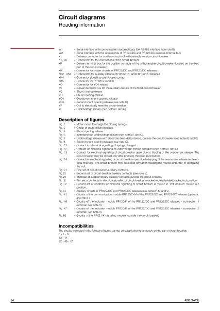
Circuit diagramsReading informationW1 = Serial interface with control system (external bus): EIA RS485 interface (see note E)W2 = Serial interface with the accessories of PR122/<strong>DC</strong> and PR123/<strong>DC</strong> releases (internal bus)X = Delivery connector for auxiliary circuits of withdrawable version circuit-breakerX1...X7 = Connectors for the accessories of the circuit-breakerXF = Delivery terminal box for the position contacts of the withdrawable circuit-breaker (located on the fixedpart of the circuit-breaker)XK1 = Connector for power circuits of PR122/<strong>DC</strong> and PR123/<strong>DC</strong> releasesXK2 - XK3 = Connectors for auxiliary circuits of PR122/<strong>DC</strong> and PR123/<strong>DC</strong> releasesXK4 = Connector signalling open/closet contactXK5 = Connector for PR120/V moduleXO = Connector for YO1 releaseXV = Delivery terminal box for the auxiliary circuits of the fixed circuit-breakerYC = Shunt closing releaseYO = Shunt opening releaseYO1 = Overcurrent shunt opening releaseYO2 = Second shunt opening release (see note Q)YR = Coil to electrically reset the circuit-breakerYU = Undervoltage release (see notes B and Q)Description of figuresFig. 1 = Motor circuit to charge the closing springs.Fig. 2 = Circuit of shunt closing release.Fig. 4 = Shunt opening release.Fig. 6 = Instantaneous undervoltage release (see notes B and Q).Fig. 7 = Undervoltage release with electronic time-delay device, outside the circuit-breaker (see notes B and Q)Fig. 8 = Second shunt opening release (see note Q).Fig. 11 = Contact for electrical signalling of springs charged.Fig. 12 = Contact for electrical signalling of undervoltage release energized (see notes B and S).Fig. 13 = Contact for electrical signalling of circuit-breaker open due to tripping of the overcurrent release. Thecircuit-breaker may be closed only after pressing the reset pushbutton.Fig. 14 = Contact for electrical signalling of circuit-breaker open due to tripping of the overcurrent release and electricalreset coil. The circuit-breaker may be closed only after pressing the reset pushbutton or energizingthe coil.Fig. 21 = First set of circuit-breaker auxiliary contacts.Fig.22 = Second set of circuit-breaker auxiliary contacts (see note V).Fig.23 = Third set of supplementary auxiliary contacts outside the circuit-breaker.Fig. 31 = First set of contacts for electrical signalling of circuit-breaker in racked-in, test isolated, racked-out position.Fig. 32 = Second set of contacts for electrical signalling of circuit-breaker in racked-in, test isolated, racked-outposition.Fig.42 = Auxiliary circuits of PR122/<strong>DC</strong> and PR123/<strong>DC</strong> releases (see notes F, M and V).Fig. 45 = Circuits of the communication module PR120/D-M of the PR122/<strong>DC</strong> and PR123/<strong>DC</strong> releases (optional,see note E).Fig. 46 = Circuits of the indicator module PR120/K of the PR122/<strong>DC</strong> and PR123/<strong>DC</strong> releases - connection 1(optional; see note V).Fig. 47 = Circuits of the indicator module PR120/K of the PR122/<strong>DC</strong> and PR123/<strong>DC</strong> releases - connection 2(optional; see note V).Fig.62 = Circuits of the PR021/K signalling module (outside the circuit-breaker)IncompatibilitiesThe circuits indicated in the following figures cannot be supplied simultaneously on the same circuit-breaker:6 - 7 - 813 - 1422 - 46 - 4734ABB <strong>SACE</strong>


