Orion® EQ-1 Equatorial Mount
Orion® EQ-1 Equatorial Mount
Orion® EQ-1 Equatorial Mount

Create successful ePaper yourself
Turn your PDF publications into a flip-book with our unique Google optimized e-Paper software.
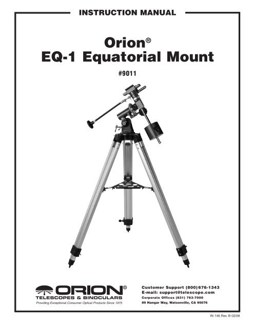
instruction ManualOrion ®<strong>EQ</strong>-1 <strong>Equatorial</strong> <strong>Mount</strong>#9011Providing Exceptional Consumer Optical Products Since 1975Customer Support (800) 676-1343E-mail: support@telescope.comCorporate Offices (831) 763-700089 Hangar Way, Watsonville, CA 95076IN 146 Rev. B 02/09
<strong>Mount</strong>ing platformR.A. lock thumb screwDec. slow-motion controlLatitude adjustment t-boltLatitude lock t-boltDec. lock thumb screw(not shown)R.A. slow-motion controlCounterweight lock knobCounterweightCounterweight shaftTripod leg attachment boltAzimuth lock knobAccessory tray bracketAccessory trayLeg lock knobFigure 1. <strong>EQ</strong>-1 <strong>Equatorial</strong> <strong>Mount</strong> parts diagram2
Congratulations on your purchase of a quality Orion product. Your new <strong>EQ</strong>-1 <strong>Equatorial</strong> <strong>Mount</strong> wasdesigned to work with many different telescope optical tubes. With its precision equatorial head, you’llbe able to easily track astronomical objects over time so that they remain within your eyepiece’s field ofview. The setting circles will help locate hundreds of fascinating celestial denizens, including galaxies,nebulas, and star clusters. With a little practice and a little patience, you’ll find that your <strong>EQ</strong>-1 <strong>Equatorial</strong><strong>Mount</strong> is an invaluable tool for getting the most out of your astronomical observing sessions.These instructions will help you set up and properly use your equatorial mount. Please read them overthoroughly before getting started.Table of Contents1. Parts List............................................................................................................................... 32. Assembly............................................................................................................................... 33. Attaching A Telescope........................................................................................................... 44. Balancing the Telescope....................................................................................................... 55. Setting Up and Using the <strong>Equatorial</strong> <strong>Mount</strong>.......................................................................... 66. Specifications...................................................................................................................... 107. Suggested Accessories....................................................................................................... 101. Parts ListQty. Description1 German-type equatorial mount1 Latitude adjustment t-bolt2 Slow-motion control cables1 Counterweight1 Counterweight shaft3 Tripod legs3 Tripod leg attachment bolts with wing nutsand washers3 Leg lock knobs1 Accessory tray3 Accessory tray screws with wing nuts andwashers1 Assembly tool2. AssemblyCarefully open all of the boxes in the shipping container.Make sure all the parts listed in Section 1 are present.Save the original boxes and packaging material. In theunlikely event that you need to return the telescope,you must use the original packaging.Note: The <strong>EQ</strong>-1<strong>Equatorial</strong> <strong>Mount</strong> is packaged with one empty interior box; thebox is included for structural integrity only.Assembling the mount for the first time should takeabout 30 minutes. No tools are needed, other than theone provided. All bolts should be tightened securelyto eliminate flexing and wobbling, but be careful not toover-tighten or the threads may strip. Refer to Figure 1during the assembly process.1. Lay the equatorial mount on its side. Attach the tripodlegs, one at a time, to the base of the mount bysliding a tripod leg attachment bolt through the top ofa leg and through the holes in the base of the mount.The washers should be on the outside of the tripodlegs. Secure the wing nuts finger-tight. Note that thehinged accessory tray bracket on each leg shouldface inward.2. Attach and tighten the leg lock knobs at the base ofthe tripod legs. For now, keep the legs at their shortest(fully retracted) length; you can extend them to amore desirable length later, after the mount is completelyassembled.3. With the tripod legs now attached to the equatorialmount, stand the tripod upright (be careful!) andspread the legs apart enough to attach the accessorytray to the three hinged tray brackets on thelegs. The slots in the brackets should be positionedunderneath the holes in the three corners of the tray.Use the three small accessory tray screws and wing3
nuts provided to fasten the tray to the brackets. Donot tighten the wing nuts yet.4. With the accessory tray attached loosely, spreadthe tripod legs apart as far as they will go, until theaccessory tray brackets are taut. Then tighten thewing nuts.5. Next, tighten the wing nuts on the tripod leg attachmentbolts at the base of the equatorial mount, sothat the legs are securely fastened. You can usethe provided assembly tool to hold the heads of thebolts while firmly tightening the wing nuts.6. Thread the latitude adjustment t-bolt into the holein the rear of the equatorial mount (see Figure 2).Orient the mount as it appears in Figure 2, at a latitudeof about 40°, i.e., so that the pointer next to thelatitude scale is pointing to the hash mark at "40."To do this, loosen the latitude lock t-bolt (central tothe latitude scale), and turn the latitude adjustmentt-bolt until the pointer and the "40" line up. Then retightenthe latitude lock t-bolt. You may also needto rotate the mount about its right ascension (R.A.)and declination (Dec.) axes (see Figure 2). Do thisby first loosening the R.A. and Dec. lock thumbscrews.7. Slide the counterweight onto the counterweightshaft. Make sure the counterweight lock knob isadequately loosened so the counterweight shaft canpass through the hole in the counterweight.8. With the counterweight lock knob still loose, grip thecounterweight with one hand and thread the shaftinto the equatorial mount (at the base of the declinationaxis) with the other hand. When it is threaded asfar in as it will go, position the counterweight abouthalfway up the shaft and tighten the counterweightlock knob. The washer and screw on the end of thecounterweight shaft will prevent the counterweightfrom slipping off the shaft and possibly onto your footif the counterweight lock knob should come loose9. Now attach the two slow-motion cables to the R.A.and Dec. slow-motion shafts (see Figure 2) of theequatorial mount by positioning the thumb screw onthe end of the cable over the indented slot on theshaft, then tightening the thumb screw. A cable canbe attached to either end of the R.A. shaft, whicheveris most convenient for you. Use the shortercable for the R.A. shaft.3. Attaching a TelescopeThe <strong>EQ</strong>-1 <strong>Equatorial</strong> <strong>Mount</strong> is designed to hold smallto mid-size telescopes weighing up to about 7 lbs. Forheavier telescopes, the mount may not provide sufficientstability for steady imaging. Any type of telescopecan be mounted on the <strong>EQ</strong>-1 <strong>Equatorial</strong> <strong>Mount</strong>, includingrefractors, Newtonian reflectors, and cadadioptrics,provided a proper adapter or set of tube rings is availableto couple the tube to the mount.Orion carries a variety of differently sized tube ringsand a 1/4"-20 mounting adapter designed exclusivelyfor the <strong>EQ</strong>-1 <strong>Equatorial</strong> <strong>Mount</strong>. One of these itemsDeclination (Dec.) slowmotionshaftR.A. lock knobLatitude adjustment t-boltRight ascension axisDeclination axisDeclination (Dec.)setting circleRight ascension (R.A.)setting circleRight ascension (R.A.)slow-motion shaftLatitude scaleLatitude locking t-boltFigure 2. The equatorial mount4
probably fits the telescope tube you wish to mount. Seethe list of Suggested Accessories at the end of theseinstructions, or check the Orion print or online catalogsfor currently available mounting accessories. Themounting accessories fasten to the two holes in the topplatform of the equatorial mount.4. Balancing the TelescopeOnce the telescope is attached to the equatorial mount,the next step is to balance the telescope. Proper balanceis required to insure smooth movement of thetelescope on both axes of the equatorial mount.If you attach your telescope with a 1/4"-20 adapter, itmay not be possible to balance the scope precisely withrespect to the declination axis, because the telescopecannot be moved back and forth as it can when tuberings are used.Assuming you will be using tube rings, we will first balancethe telescope with respect to the R.A. axis, thenthe Dec. axis.1. Keeping one hand on the telescope optical tube,loosen the R.A. lock thumb screw. Make sure theDec. lock thumb screw is locked, for now. The telescopeshould now be able to rotate freely about theR.A. axis. Rotate it until the counterweight shaft isparallel to the ground (i.e., horizontal).2. Now loosen the counterweight lock knob and slidethe weight along the shaft until it exactly counterbalancesthe telescope (Figure 3a). That’s the point atwhich the shaft remains horizontal even when youlet go of the telescope with both hands (Figure 3b).Retighten the counterweight lock knob. The telescopeis now balanced on the R.A. axis.3. To balance the telescope on the Dec. axis (this is notpossible if using a 1/4"-20 mounting adapter), firsttighten the R.A. lock thumb screw, with the counterweightshaft still in the horizontal position.4. With one hand on the telescope optical tube, loosenthe Dec. lock thumb screw (Figure 3c). The telescopeshould now be able to rotate freely about the Dec.axis.Figure 3a. Balancing the telescope with respect tothe R.A. axis by sliding the counterweight along itsshaft.Figure 3b. Telescope is now balanced on the R.A. axis. That is,when hands are released, counterweight shaft remains horizontal.Figure 3c. Preparing the telescope to be balancedon the Dec. axis by first releasing the Dec. lock knob.5
Loosen the tube ring clamps a few turns until youcan slide the telescope tube forward and back insidethe rings (this can be aided by using a slight twistingmotion on the optical tube while you push or pull on it)(Figure 3d). Position the telescope so that it remainshorizontal when you carefully let go with both hands.This is the balance point for the Dec. axis (Figure 3e).Before clamping the rings tight again, rotate the telescopeso that the eyepiece is at a convenient angle forviewing.Figure 3d. Balancing the telescope with respect tothe Dec. axis. As shown here, the telescope is out ofbalance (tilting).Figure 3e. Telescope is now balanced on the Dec.axis, i.e., it remains horizontal when handsare released.The telescope is now balanced on both axes. Now whenyou loosen the lock thumb screw on one or both axesand manually point the telescope, it should move withoutresistance and should not drift from where you point it.5. Setting Up and Usingthe <strong>Equatorial</strong> <strong>Mount</strong>When you look at the night sky, you no doubt havenoticed that the stars appear to move slowly from eastto west over time. That apparent motion is caused bythe Earth’s rotation (from west to east). An equatorialmount (Figure 2) is designed to compensate for thatmotion, allowing you to easily "track" the movementof astronomical objects, thereby keeping them fromdrifting out of the telescope’s field of view while you’reobserving.This is accomplished by slowly rotating the telescopeon its right ascension (polar) axis, using only the R.A.slow-motion cable. But first the R.A. axis of the mountmust be aligned with the Earth’s rotational (polar) axis;this is a process called polar alignment.Polar AlignmentFor Northern Hemisphere observers, approximatepolar alignment is achieved by pointing the mount’sR.A. axis at the North Star, or Polaris. It lies within 1°of the north celestial pole (NCP), which is an extensionof the Earth’s rotational axis out into space. Starsin the Northern Hemisphere appear to revolve aroundPolaris.To find Polaris in the sky, look north and locate thepattern of the Big Dipper (Figure 4). The two stars atthe end of the "bowl" of the Big Dipper point right toPolaris.Observers in the Southern Hemisphere aren’t so fortunateto have a bright star so near the south celestialpole (SCP). The star Sigma Octantis lies about 1° fromthe SCP, but it is barely visible with the naked eye(magnitude 5.5).For general visual observation, an approximate polaralignment is sufficient:1. Level the equatorial mount by adjusting the length ofthe three tripod legs.2. Loosen the latitude lock t-bolt. Turn the latitudeadjustment t-bolt and tilt the mount until the pointeron the latitude scale is set at the latitude of yourobserving site. If you don’t know your latitude, consulta geographical atlas to find it. For example, ifyour latitude is 35° North, set the pointer to +35.Then retighten the latitude lock t-bolt. The latitudesetting should not have to be adjusted again unlessyou move to a different viewing location some distanceaway.3. Loosen the Dec. lock thumb screw and rotate thetelescope optical tube until it is parallel with the R.A.6
axis. The pointer on the Dec. setting circle shouldread 90°. Retighten the Dec. lock thumb screw.4. Loosen the azimuth adjustment knob and rotate theentire equatorial mount left-to-right so the telescopetube (and R.A. axis) points roughly at Polaris. If youcannot see Polaris directly from your observing site,consult a compass and rotate the equatorial mountso the telescope points North. Retighten the azimuthadjustment knob.The equatorial mount is now approximately polar-alignedfor casual observing. More precise polar alignment isrequired for astrophotography. Several methods existand are described in many amateur astronomy referencebooks and astronomy magazines.From this point on in your observing session, you shouldnot make any further adjustments to the azimuth or thelatitude of the mount, nor should you move the tripod.Doing so will undo the polar alignment. The telescopeshould be moved only about its R.A. and Dec. axes.Use of the R.A. and Dec. Slow-MotionControl CablesThe R.A. and Dec. slow-motion control cables allowfine adjustment of the telescope’s position to centerobjects within the field of view. Before you can use thecables, you must manually "slew" the mount to pointthe telescope in the vicinity of the desired target. Dothis by loosening the R.A. and Dec. lock thumb screwsand moving the telescope about the mount’s R.A. andDec. axes. Once the telescope is pointed somewhereclose to the object to be viewed, retighten the mount’sR.A. and Dec. lock thumb screws.The object should now be visible somewhere in thetelescope’s (aligned) finder scope. If it isn’t, use theslow-motion controls to scan the surrounding area ofsky. If the object is still not visible in the finder scope,you will need to slew the mount again, this time beingmore careful to point the telescope closer to what youwish to view.When the object is visible in the finder scope, use the slowmotioncontrols to center it. Now, look in the telescopewith a long focal length (low magnification) eyepiece. Ifthe finder scope is properly aligned, the object should bevisible somewhere in the field of view. If it is not, you mayneed to realign the telescope’s finder scope.Once the object is visible in the telescope’s eyepiece,use the slow-motion controls to center it in the fieldof view. You can now switch to a higher magnificationeyepiece, if you wish. After switching eyepieces, youcan use the slow-motion control cables to re-center theimage, if necessary.Little Dipper(in Ursa Minor)Big Dipper(in Ursa Major)N.C.P.PolarisCassiopeiaPointer StarsTo find Polaris in the night sky, look north and find the Big Dipper. Extend an imaginary line from the two “PointerStars” in the bowl of the Big Dipper. Go about 5 times the distance between those stars and you’ll reach Polaris,which lies within 1° of the north celestial pole (NCP).Figure 4. Finding Polaris7
The Dec. slow-motion control cable can move thetelescope a maximum of 25°. This is because theDec. slow-motion mechanism has a limited range ofmechanical travel. (The R.A. slow-motion mechanismhas no limit to its amount of travel.) If you can no longerrotate the Dec. control cable in a desired direction, youhave reached the end of travel, and the slow-motionmechanism should be reset. This is done by first rotatingthe control cable several turns in the opposite directionfrom which it was originally being turned. Then, manuallyslew the telescope closer to the object you wish toobserve (remember to first loosen the Dec. lock thumbscrew). You should now be able to use the Dec. slowmotioncontrol cable again to fine adjust the telescope’sposition.Tracking Celestial ObjectsWhen you observe a celestial object through the telescope,you’ll see it drift slowly across the field of view.To keep it in the field, if your equatorial mount is polaraligned,just rotate the R.A. slow-motion control. TheDec. slow-motion control is not needed for tracking.Objects will appear to move faster at higher magnifications,because the field of view is narrower.Optional Motor Drives for AutomaticTracking and AstrophotographyAn optional DC motor drive (<strong>EQ</strong>-1M, Orion part #7826)can be mounted on the R.A. axis of the <strong>EQ</strong>-1 <strong>Equatorial</strong><strong>Mount</strong> to provide hands-free tracking. Objects will thenremain stationary in the field of view without any manualadjustment of the R.A. slow-motion control. The motordrive is necessary for astrophotography.Understanding the Setting CirclesThe setting circles on an equatorial mount enable you tolocate celestial objects by their "celestial coordinates."Every astronomical object resides in a specific locationon the "celestial sphere." That location is denoted bytwo numbers: its right ascension (R.A.) and declination(Dec.). In the same way, every location on Earth can bedescribed by its longitude and latitude. R.A. is similar tolongitude on Earth, and Dec. is similar to latitude. TheR.A. and Dec. values for celestial objects can be foundin any star atlas or star catalog.So, the coordinates for the Orion Nebula listed in a staratlas will look like this:R.A. 5h 35.4m Dec. -5° 27'That’s 5 hours and 35.4 minutes in right ascension, and-5 degrees and 27 arc-minutes in declination (the negativesign denotes south of the celestial equator). Thereare 60 minutes in 1 hour of R.A and there are 60 arcminutesin 1 degree of declination.The mount’s R.A. setting circle is scaled in hours, from1 through 24, with small hash marks in between representing10 minute increments. The numbers closestto the R.A. axis gear apply to viewing in the SouthernHemisphere, while the numbers above them apply toviewing in the Northern Hemisphere. The Dec. settingcircle is scaled in degrees, with each small hash markrepresenting 2.5°.Before you can use the setting circles to locate objects,the mount must be well polar aligned, and the settingcircles must be calibrated. The declination setting circlewas calibrated at the factory, and should read 90° whenthe telescope optical tube is parallel with the R.A. axis.Calibrating the Right AscensionSetting Circle1. Identify a bright star near the celestial equator andlook up its coordinates in a star atlas.2. Loosen the R.A. and Dec. lock thumb screws on theequatorial mount, so the telescope optical tube canmove freely.3 Point the telescope at the bright star near the celestialequator whose coordinates you know. Center thestar in the telescope’s field of view. Lock the R.A. andDec. lock thumb screws.4. Rotate the R.A. setting circle so the pointer indicatesthe R.A. listed for the bright star in the star atlas.Finding Objects With the Setting CirclesNow that both setting circles are calibrated, look up in astar atlas the coordinates of an object you wish to view.1. Loosen the Dec. lock thumb screw and rotate thetelescope until the Dec. value from the star atlasmatches the reading on the Dec. setting circle.Retighten the lock thumb screw. Note: If the telescopeis aimed south and the Dec. setting circlepointer passes the 0° indicator, the value on the Dec.setting circle becomes a negative number.2. Loosen the R.A. lock thumb screw and rotate the telescopeuntil the R.A. value from the star atlas matchesthe reading on the R.A. setting circle. Retighten thelock thumb screw.Most setting circles are not accurate enough to putan object dead-center in your finder scope’s field ofview, but they’ll get you close, assuming the equatorialmount is accurately polar-aligned. The R.A. setting circleshould be re-calibrated every time you wish to locate anew object. Do so by calibrating the setting circle for thecentered object before moving on to the next one.8
Confused About Pointing the Telescope?Beginners occasionally experience some confusionabout how to point the telescope overhead or in otherdirections. In Figure 1 the telescope is pointed north asit would be during polar alignment. The counterweightshaft is oriented downward. But it will not look like thatwhen the telescope is pointed in other directions. Let’ssay you want to view an object that is directly overhead,at the zenith. How do you do it?One thing you DO NOT do is make any adjustment tothe latitude adjustment t-bolt. That will nullify the mount’spolar alignment. Remember, once the mount is polaraligned,the telescope should be moved only on the R.A.and Dec. axes. To point the scope overhead, first loosenthe R.A. lock thumb screw and rotate the telescope onthe R.A. axis until the counterweight shaft is horizontal(parallel to the ground). Then loosen the Dec. lockthumb screw and rotate the telescope until it is pointingstraight overhead. The counterweight shaft is still horizontal.Then retighten both lock thumb screws.Similarly, to point the telescope directly south, the counterweightshaft should again be horizontal. Then yousimply rotate the scope on the Dec. axis until it points inthe south direction. (Figure 5a)What if you need to aim the telescope directly north, butat an object that is nearer to the horizon than Polaris?You can’t do it with the counterweight down as picturedin Figure 1. Again, you have to rotate the scope in R.A.so that the counterweight shaft is positioned horizontally.Then rotate the scope in Dec. so it points to where youwant it near the horizon. (Figure 5b)Figure 5a. Telescope pointing south. Note that inall these illustrations, the mount and tripod remainstationary; only the R.A. and Dec. axes are moved.Figure 5b. Telescope pointing north.Figure 5c. Telescope pointing east.Figure 5d. Telescope pointing west.9
To point the telescope to the east (Figure 5c) or west(Figure 5d), or in other directions, you rotate the telescopeon its R.A. and Dec. axes. Depending on thealtitude of the object you want to observe, the counterweightshaft will be oriented somewhere betweenvertical and horizontal.The key things to remember when pointing the telescopeis that a) you only move it in R.A. and Dec., not inazimuth or latitude (altitude), and b) the counterweightand shaft will not always appear as it does in Figure 1.In fact it almost never will!6. Specifications<strong>Mount</strong>: German-type equatorialTripod: aluminumHeight: 36" to 57"Weight: 11.9 lbsCounterweight: 5 lb. suppliedMaximum Loading Weight: about 7 lbsSlow-Motion Adjustment: both RA and Dec axesSetting Circles: RA scaled in 10 min. increments, Decscaled in 2.5° increments, for N or S HemispherePolar Axis Altitude Adjustment: 10° to 70°7. Suggested Accessories1/4"-20 Adapter (Orion part #10103)This accessory bolts to the top of the equatorial headand provides a threaded post on which to mount a cameraor telescope that utilizes a standard 1/4"-20 thread.Tube <strong>Mount</strong>ing RingsThese quality metal rings are custom-made for use withthe <strong>EQ</strong>-1 <strong>Mount</strong>. They are hinged for easy installationof a telescope tube and are lined with felt to preventscratching. Check the outer diameter of your telescope;if it matches the inner diameter (I.D.) of the rings, thenthe rings will fit. If the outer diameter of your telescopeis a little smaller than the I.D. of the rings, that is alsoacceptable; you can "shim" the inside of the rings withextra felt. Two rings are included in a set.I.D. 3.0": Orion part #7369I.D. 3.5": Orion part #7370I.D. 3.9": Orion part #7371I.D. 4.6": Orion part #7372I.D. 5.5": Orion part #7373<strong>EQ</strong>-1M Motor Drive (Orion part #7826)This is a small electric motor that attaches to the equatorialmount. It turns the gear on the R.A. axis at the samerate that the Earth rotates on its axis, thereby following,or "tracking," the apparent motion of the stars. Automatictracking keeps objects from drifting out of the field of viewwhile you’re observing, and is required for astrophotography.Runs on four size "D" alkaline batteries.10
One-Year Limited WarrantyThis Orion <strong>EQ</strong>-1 <strong>Equatorial</strong> <strong>Mount</strong> is warranted against defects in materials or workmanship for aperiod of one year from the date of purchase. This warranty is for the benefit of the original retailpurchaser only. During this warranty period Orion Telescopes & Binoculars will repair or replace,at Orion’s option, any warranted instrument that proves to be defective, provided it is returnedpostage paid to: Orion Warranty Repair, 89 Hangar Way, Watsonville, CA 95076. If the product isnot registered, proof of purchase (such as a copy of the original invoice) is required.This warranty does not apply if, in Orion’s judgment, the instrument has been abused, mishandled,or modified, nor does it apply to normal wear and tear. This warranty gives you specific legalrights, and you may also have other rights, which vary from state to state. For further warrantyservice information, contact: Customer Service Department, Orion Telescopes & Binoculars, 89Hangar Way, Watsonville, CA 95076; (800) 676-1343.Orion Telescopes & Binoculars89 Hangar Way, Watsonville, CA 95076Customer Support Help Line (800) 676-1343 • Day or Evening11