User manual and Installation instructions - Biasi
User manual and Installation instructions - Biasi
User manual and Installation instructions - Biasi

Create successful ePaper yourself
Turn your PDF publications into a flip-book with our unique Google optimized e-Paper software.
Wall hung, fan flue, room sealed, high efficiency gas boiler<strong>User</strong> <strong>manual</strong> <strong>and</strong><strong>Installation</strong> <strong>instructions</strong>RIVA COMPACT HEModelsM96.24SM/CM96.28SM/CM96.28SR/CThis product has an energy rating B on a scale of A to GFor more information see www.boilers.org.ukThis is a certification mark
Congratulations on your choice.RIVA COMPACT HE are condensing high efficiency sealed chamber fan flue gas boilers.They are fully electronically controlled <strong>and</strong> have electronic ignition.The materials they are made of <strong>and</strong> the control systemsthey are equipped with give you safety,a high level of comfort <strong>and</strong> energy savings to allow you to get the greatest benefit out ofindependent heating.RIVA COMPACT HE allow a higher efficiency by reducing the flue gas temperature such thatthe water vapour formed during the combustion is condensed out.This allows a gain of useful heat that otherwise would be lost.Remember that...n The <strong>manual</strong>--- must be read thoroughly, so that you willbe able to use the boiler in a safe <strong>and</strong> sensibleway;--- must be carefully kept. It may be necessaryfor reference in the future.n First lighting up must be carried out bycompetent <strong>and</strong> responsible engineer.n The manufacturer--- disclaim all liability for any translations ofthe present <strong>manual</strong> from which incorrect interpretationmay occur--- cannot be held responsible for non---observanceof <strong>instructions</strong> contained in this<strong>manual</strong> or for the consequences of any procedurenot specifically described.Using the boiler...n Before lighting the boiler you are advisedto have a professionally qualified personcheck that the installation of the gassupply--- is gas---tight;--- is of the correct gauge for the flow to theboiler;--- is fitted with all the safety <strong>and</strong> control devicesrequired by the current Regulations.n Ensure that--- the installer has connected the pressurerelief valve outlet to a drain pipe. The manufacturersare not responsible for damagecaused by opening of the pressure reliefvalve <strong>and</strong> consequent escape of water, if notconnected correctly to the drain.--- the installer has connected the condensateoutlet to a suitable drain pipe.n On detecting the smell of gas--- don’t operate any electrical switches, thetelephone or any device that may producesparks;--- open the windows <strong>and</strong> doors at once tocreate a draught of air which will purge thearea;--- shut off the gas cocks;--- get the assistance of a qualified person.n Do not touch the appliance with parts ofthe body that are wet or damp <strong>and</strong>/or barefeet.n Do not block or modify the condensateoutlet <strong>and</strong> pipeworkn In case of structural work or maintenancenear the exhaust duct <strong>and</strong>/or fume exhaustdevices or their attachments, turn offthe appliance. On completion of the work,have a professionally qualified person checktheir efficiency.n Repairs (under guarantee) must be carriedout only by an approved engineer, usinggenuine spare parts. Thus do no more thanswitching off the boiler yourself (see the <strong>instructions</strong>).n Your boiler allows heating up of water toa temperature less than boiling point;--- must be connected to a central heatingsystem <strong>and</strong>/or a hot water supply system,compatible with its performance <strong>and</strong> output;
--- can be used only for those purposes forwhich it has been specially designed;--- must not be touched by children or bythose unfamiliar with its operation;--- must not be exposed to weather conditions.n During the operation it is quite normalthat the boiler produces a white plume ofcondensation vapour from the flue terminal.This is due to the high efficiency of the appliance<strong>and</strong> may be particularly evident withlow outdoor temperatures.Safe h<strong>and</strong>ling ofsubstances<strong>Biasi</strong> products are manufactured in accordancewith ISO 9000 <strong>and</strong> do not, <strong>and</strong> will not, contain anyhazardous materials or substances such as asbestos,mercury or C.F.C.’s.The appliance packaging does not contain anysubstances, which may be considered a hazard tohealth.Combustion chamber panelsMaterial: mineral fibersKnown hazards --- Some people can suffer reddening<strong>and</strong> itching of the skin. Fibre entry into theeye will cause foreign body irritation, which cancause severe irritation to people wearing contactlenses. Irritation to respiratory tract.Precautions --- Dust goggles will protect eyes.People with a history of skin complaints may beparticularly susceptible to irritation. High dust levelsare only likely to arise following harsh abrasion.In general, normal h<strong>and</strong>ling <strong>and</strong> use willnot present high risk, follow good hygiene practices,wash h<strong>and</strong>s before, touching eyes, consumingfood, drinking or using the toilet.First aid --- Medical attention must be sought followingeye contact or prolonged reddening of theskin.Thermostat / Temperature gaugeDescription --- Sealed phial <strong>and</strong> capillary containingliquid.Known hazards --- irritating to skin, eyes <strong>and</strong>throat. Vapour is harmful. Inflammable --- do notextinguish with water.Precautions --- Do not incinerate. Avoid contactwith broken/leaking phials. Do not purposelypuncture.First aid medical attention must be sought followingeyes/skin contact, wash with clean water.Appliance category II 2H3+ Gas G20 20 mbar, G30 29 mbar, G31 37 mbarCountry of destination: United KingdomThis appliance conforms with the EEC directive 90/396 <strong>and</strong>, consequently, it has the right to make useof the br<strong>and</strong> nameMoreover, the appliance conforms with the EEC directive 87/308 relative to the prevention <strong>and</strong> eliminationof radio disturbances.The appliance is built to comply with the regulation now in force regarding gas appliance’s safety <strong>and</strong>the European regulation now in force relative to safety of household <strong>and</strong> similar electrical appliances.The manufacturer, in the continuous pocess to improve his products, reserves the right to modify thedata expressed in the present documentation at any time <strong>and</strong> without prior notice.The present documentation is an informative support <strong>and</strong> it cannot be considered as a contract towardsthird parties.
Boiler installation <strong>and</strong> commissioning tipsn The installation must be carried out bya qualified person who will be responsible forobserving the current Regulations.Installing the boiler...n Do not forget to remove the transit caps<strong>and</strong> plugs from the boiler connections theseare fitted to every boiler.n Keep the boiler clear of dust during installation<strong>and</strong> in particular do not allow anydust or debris to enter the top of the boilerwhere the flue connection is made. It is recommendedthat you put a dust sheet over thetop of the boiler until you are ready to makethe flue connection.n Because every boiler is fired <strong>and</strong> testedlive at the factory, a small amount of water remainswithin the boiler. It is possible for thiswater to initially cause the pump to seize. It istherefore recommended that the pump rotorbe <strong>manual</strong>ly turned to free its rotation beforeturning the boiler on.n Remember to release the auto air purgebefore filling the boiler. See the <strong>instructions</strong> toidentify the location of this device.n Do not remove the cap of the pressuretest points of the air switch (top left side of theboiler).n You are strongly advised to flush out thesystem both cold <strong>and</strong> hot in order to removesystem <strong>and</strong> installation debris.n It is also sensible to initially fire <strong>and</strong> commissionthe boiler before connecting any externalcontrols such as a room thermostat. Bythis method if you have a subsequent problemfollowing the addition of an external controlyou can eliminate the boiler from yourfault analysis.n Do not forget to range rate the boiler tosuit the system requirements. This procedureis covered in the commissioning sectionof the installation <strong>manual</strong>.n If the boiler is fitted with a digital programmer,when setting the times for automaticoperation, remember that for every“ON” time there must be an “OFF” time to follow<strong>and</strong> that on every occasion you enter atime you must also indicate which days thatyou want the boiler to follow the timed settings.n Some products incorporate an anti cyclingtime delay. It is normal when first switchingthe boiler on for the boiler to operate onheating for a few seconds then switch off.After 3---4 minutes has elapsed the boiler willthen re ignite <strong>and</strong> operate perfectly normally.The ignition delay cycle does not preventnormal operation of the boiler to provided.h.w.n If you are in any doubts as to the installationor operation of the boiler please read theinstruction <strong>manual</strong>s thoroughly <strong>and</strong> then ifnecessary contact <strong>Biasi</strong> UK for advice <strong>and</strong>assistance.Please remember that if you are in any doubt about the installation of this product you can contact ourTechnical Helpline on tel. 01902 304400
TABLE OF CONTENTS1 Appliance description . . . . . . . . . . 21.1 Overview . . . . . . . . . . . . . . . . . . . . . . 21.2 Control panel . . . . . . . . . . . . . . . . . . 21.3 Isolation valves . . . . . . . . . . . . . . . . . 21.4 Technical data . . . . . . . . . . . . . . . . . 21.5 Operation lights . . . . . . . . . . . . . . . . 32 Instructions for use . . . . . . . . . . . . 42.1 Warnings . . . . . . . . . . . . . . . . . . . . . . 42.2 Refilling procedure . . . . . . . . . . . . . . 42.3 Ignition . . . . . . . . . . . . . . . . . . . . . . . . 52.4 C.h. circuit temperature . . . . . . . . . . 52.5 D.h.w. temperature (combi) . . . . . . 62.6 Extinguishing . . . . . . . . . . . . . . . . . . 62.7 Built in time switch . . . . . . . . . . . . . . 73 Useful advice . . . . . . . . . . . . . . . . . 103.1 Central heating . . . . . . . . . . . . . . . . . 103.2 Frost protection . . . . . . . . . . . . . . . . 103.3 Periodic maintenance . . . . . . . . . . . 103.4 External cleaning . . . . . . . . . . . . . . . 103.5 Operational faults . . . . . . . . . . . . . . . 10USE4 Technical information . . . . . . . . . . 124.1 Overview . . . . . . . . . . . . . . . . . . . . . . 124.2 Main diagram (combi) . . . . . . . . . . . 134.3 Main diagram (c.h. only) . . . . . . . . . 144.4 Hydraulic specifications . . . . . . . . . 154.5 Expansion vessel . . . . . . . . . . . . . . . 154.6 Technical data M96.24SM/... . . . . . . 164.7 Technical dataM96.28SM/... M96.28SR/... . . . . . . . 185 General requirements . . . . . . . . . . 205.1 Related documents . . . . . . . . . . . . . 205.2 Location of appliance . . . . . . . . . . . 205.3 Flue system . . . . . . . . . . . . . . . . . . . . 205.4 Gas supply . . . . . . . . . . . . . . . . . . . . 215.5 Air supply . . . . . . . . . . . . . . . . . . . . . 215.6 Ventilation . . . . . . . . . . . . . . . . . . . . . 215.7 Condensate drain . . . . . . . . . . . . . . 215.8 Water circulation (c.h.) . . . . . . . . . . . 215.9 Domestic water . . . . . . . . . . . . . . . . . 225.10 Water treatment . . . . . . . . . . . . . . . . 225.11 Electrical supply . . . . . . . . . . . . . . . . 236 <strong>Installation</strong> . . . . . . . . . . . . . . . . . . . . 246.1 Warnings . . . . . . . . . . . . . . . . . . . . . . 246.2 Precautions for installation . . . . . . . 248 Gas conversion . . . . . . . . . . . . . . . 368.1 Warnings . . . . . . . . . . . . . . . . . . . . . . 368.2 Procedures . . . . . . . . . . . . . . . . . . . . 369 Maintenance . . . . . . . . . . . . . . . . . . 379.1 Warnings . . . . . . . . . . . . . . . . . . . . . . 379.2 Dismantling the external panels . . . 379.3 Emptying the d.h.w. system (combi) 379.4 Emptying the c.h. system . . . . . . . . 376.3 Installing the bracket . . . . . . . . . . . . 246.4 Overall dimensions . . . . . . . . . . . . . 256.5 Joints . . . . . . . . . . . . . . . . . . . . . . . . . 256.6 Mounting the boiler . . . . . . . . . . . . . 256.7 Fitting the flue system . . . . . . . . . . . 266.8 Choice of flue . . . . . . . . . . . . . . . . . . 266.9 Electrical connections . . . . . . . . . . . 276.10 External frost protection . . . . . . . . . 296.11 Connecting a M96.28SR/...system boiler to a cylinder . . . . . . . 297 Commissioning . . . . . . . . . . . . . . . 317.1 Electrical installation . . . . . . . . . . . . 317.2 Gas supply installation . . . . . . . . . . 317.3 Filling the d.h.w. system . . . . . . . . . 317.4 Initial filling of the system . . . . . . . . 317.5 Condensate pipe <strong>and</strong> traps . . . . . . 327.6 Lighting the boiler . . . . . . . . . . . . . . 327.7 Checking the gas pressureat the burner . . . . . . . . . . . . . . . . . . . 327.8 Adjusting the burner ignition . . . . . 337.9 Adjustment of useful c.h. output . . 347.10 Checking the ignition device . . . . . 357.11 Checking the flue system . . . . . . . . 357.12 Checking the condensate drain pipe 357.13 Instructing the user . . . . . . . . . . . . . 359.5 Combustion analysis check . . . . . . 389.6 Cleaning the primary heat exchanger 389.7 Checking the pressurisationin the expansion vessel . . . . . . . . . . 389.8 Cleaning the burner . . . . . . . . . . . . . 389.9 Checking the flue . . . . . . . . . . . . . . . 389.10 Drain pipe inspection . . . . . . . . . . . . 389.11 Visual inspection of appliance . . . . 389.12 Gas pressures <strong>and</strong> soundness . . . 38INSTALLATIONMAINTENANCEAbbreviations used in the <strong>manual</strong>C.h. = Central heatingD.h.w. = Domestic hot waterD.c.w. = Domestic cold water1
1 APPLIANCE DESCRIPTION1.1 Overview9 D.h.w. temperature control knob *10 Appliance operation lightsUSE1.3 Isolation valves11623Fig. 1.11 Case front panel2 Control panel3 Control panel cover1.2 Control panel4 C.h. circuit temperature <strong>and</strong> pressure gauge5 Time switch (c.h. control) *6 Lock---out signal lamp7 Lockout reset button8 Function selector <strong>and</strong> c.h. temp. control knob15141312Fig. 1.2 (bottom view of the boiler)11 Condensate drain pipe12 C.h. return valve13 D.c.w. inlet valve *14 Gas inlet valve15 D.h.w. outlet pipe *16 C.h. flow valve1.4 Technical data11For detailed technical data see section 4.6 or 4.7of this <strong>manual</strong>.M96.24SM/...M96.28SM/...109 8 7 6 5 4M96.28SR/...Fig. 1.32* not on M96.28SR/... boiler
Appliance description1.5 Operation lightsThree lights (10 in Fig. 1.3) give detailed indicationregarding the operation of the boiler.The following table gives the relationship betweeneach of the possible light combinations <strong>and</strong> theirmeaning.A short pulse every 4seconds:st<strong>and</strong>---by conditionFunction selector inposition.Anti---freeze system active1 second pulse every 2seconds: normallyoperating boiler. Functionselector in orpositionC.h. operationLamp OFFLamp ONFlashing lamp, alone or simultaneouslywith an other lamp.Flashing lamp, alternate with anotherlamp.USED.h.w. operation *Frost protect operationD.h.w. operationExcessive temperature onprimary circuit *Faulty c.h. temperatureprobe NTCFaulty d.h.w temperatureprobe NTC *Faulty primary circuit(no water or absence offlow)Lack of burner ignition (noignition signal from the fullseqence ignition device)Ignition gas pressureadjustmentMinimum gas pressureadjustment* not on M96.28SR/... boiler3
Instructions for use2.3 Ignition1 Check that the valves located in the lower partof the boiler are open (Fig. 2.3).USE108Fig. 2.6Fig. 2.3Open position2 Turn on the electricity supply to the boiler,switching on the fused spur isolation switch.The appliance operation light 10 (Fig. 2.4) willflash every 4 seconds (st<strong>and</strong>---by condition).3 If the boiler is to be used for c.h. <strong>and</strong> d.h.w positionthe function selector 8 as in Fig. 2.4(combi) or in Fig. 2.5 (c.h. only).The appliance operation light 10 will flashevery 2 seconds (operating boiler).1082.4 C.h. circuit temperatureThe output temperature of c.h. water is adjustablefrom a minimum of about 38°C to a maximum ofabout 85°C (Fig. 2.7), by turning the function selector(8).Adjustment of c.h. output on the boiler is automatic.The greatest output pre---set in the factorycan, however, be reduced in level according toactual system requirements; this does not affectthe maximum output in d.h.w. operation.Such adjustments must be carried out by a qualifiedperson; therefore we advise you to contactyour installer or Service Agent.Adjustment of the boiler temperature alters thegas flow at the burner according to the thermal dem<strong>and</strong>in the system. So it is usual to see the burnerlit at the minimum level for more or less longperiods.Fig. 2.4108MinimumFig. 2.54 If d.h.w. supply only is required (combi), positionthe function selector 8 as in Fig. 2.6.The appliance operation light 10 will flashevery 2 seconds (operating boiler).MaximumFig. 2.75
Instructions for useUSEAdjustmentIn order to achieve optimal settings for economy<strong>and</strong> comfort, we recommend adjusting the operatingtemperature of the c.h. water according tothe outside temperature, positioning the knob asfollows:From 5 to 15 ° CBetween---5 <strong>and</strong> +5 ° CFig. 2.8Lower than---5 ° CYour qualified installer will be able to recommendthe most suitable adjustment for your system.The temperature <strong>and</strong> pressure gauge (4, Fig. 1.3on page 2) will allow you to check that the set temperatureis obtained.The adjustment system integrated within theboiler automatically controls the flow of gas to theburner in order to keep the temperature of d.h.w.delivered constant, between the limits of maximum<strong>and</strong> minimum output.Where the dem<strong>and</strong> is at a low level or with the temperatureset to the minimum, it is normal to see acycle of lighting <strong>and</strong> extinguishing of the burnerwhen running.AdjustmentIt is advisable to adjust the d.h.w. temperature toa level commensurate with the dem<strong>and</strong>, minimisingthe need to mix with cold water. In this way, theautomatic control facilities will be fully exploited.Moreover, where the amount of limescale presentin the water may be particularly great, not exceedingthe position in Fig. 2.10 of the d.h.w. temperaturecontrol knob 9 corresponding to about 50°C(Fig. 2.10), minimises annoying incidences ofscale deposits <strong>and</strong> clogging.2.5 D.h.w. temperature (combi)The temperature of the d.h.w. leaving the boilercan be varied from a minimum of about 35°C to amaximum of about 55°C (Fig. 2.9), by turning thetemperature control knob 9.Fig. 2.109MinimumMaximum9In these cases, however, it is advisable to install asmall water treatment device or softener. Withsuch a device you should avoid periodic descaling.Consequently, the d.h.w. heat exchanger will keepits performance consistent for a longer period oftime with resulting gas savings.If the dem<strong>and</strong> for d.h.w. is so great as to preventreaching a high enough temperature, have the appropriateoutput limiting valve installed by your installeror an Authorised Service Engineer.2.6 ExtinguishingFig. 2.9Adjustment of the d.h.w. temperature is completelyseparate from that of the c.h. circuit.To turn the boiler off set the function selector 8 tothe position shown in Fig. 2.11 (combi) orFig. 2.12 (c.h. only).6
Instructions for useThe appliance operation light 10 will flash every 4seconds.1082.7 Built in time switch (combi)The combi boilers are equipped with a built in electronictime switch (5, Fig. 1.3 on page 2) whichcontrols the c.h. operation.GHUSEFig. 2.11A108FFig. 2.14EDCBFig. 2.12When you do not expect to use the boiler for a longperiod:1 Switch off the electricity supply to the boiler, bymeans of the fused spur isolation switch;2 Shut off the gas supply cock 14 <strong>and</strong> the valvesfor the water circuits fitted under the boiler(Fig. 2.13).3 Empty the water circuits, if necessary, asshown in the installation <strong>instructions</strong> in the sectionmaintenance.Display <strong>and</strong> control panelA Mode selector switchB Reset buttonC Enter buttonD Increase “+” setting buttonE Decrease “---” setting buttonF On---off buttonG Time displayH ON---OFF display14Fig. 2.13Closed positionSetting the current timeNote: with a new unit or when the reset button Bhas been pressed <strong>and</strong> the selector switch A is tothe position, the time display G is flashing.Set the mode selector switch A to the position<strong>and</strong> press the buttons D or E until the current timeappears in the display G.The clock starts by moving the switch A to theAUTO position.Setting example shown in Fig. 2.15:Current time 16.30.7
Instructions for useAAUSEFig. 2.15Setting the switching time20 memory locations are available, correspondingto 10 on---off sequences.Set the mode selector switch A to the C1 position.The symbols shown in Fig. 2.16 appears in thedisplay.Fig. 2.16Press the buttons D or E to set the desired ONtime.Press the “enter” button C to confirm the setting<strong>and</strong> to continue programming the OFF time.Set the OFF time as explained above for the ONsetting <strong>and</strong> confirm by pressing the “enter” buttonC. Proceed in the same way for other settings.Setting example shown in Fig. 2.17:A --- ON time 7.45.B --- OFF time 10.30.Fig. 2.17AActivating the timed settingsSet the mode selector switch A to the AUTO positionshown in Fig. 2.18.The current time appears in the display. The ON---OFF display H indicates the current state of operation(according to the settings).BAFig. 2.18Note: when the mode selector switch A is in theAUTO position <strong>and</strong> the boiler is switched off at thefused spur isolation switch, the display H indicatesonly the OFF state. The other indications areblanked.Reading the timed settingsSet the mode selector switch A to the C1 position.The symbols shown in Fig. 2.16 appears in thedisplay.Press the “enter” button C. Each time the buttonis pressed the display shows the details of the nextsetting.Changing or deleting the timed settingsSet the mode selector switch A to the C1 position.The symbols shown in Fig. 2.16 appears in thedisplay.Press the “enter” button C until the display showsthe setting to be modified or deleted.The time setting can be modified now by pressingbutton D or E <strong>and</strong> the operation can be switchedon or off by pressing the button F.To delete a time set press the button D or E until thesymbols shown in Fig. 2.16 appears in the timedisplay G.The new settings are memorized by moving theswitch A to a different position.Manual operationThe operation of the time switch can be forced onor off constantly or for a timed period.To force constantly on or off the timer operationset the mode selector switch A to the TIMER position.The symbols shown in Fig. 2.19 appears onthe display.8
Instructions for useFig. 2.19The operation can be switched permanently on oroff by pressing the button F <strong>and</strong> leaving the switchA in the TIMER position.To force a timed delay on or off operation, set themode selector switch A in the TIMER position.Set the time delay by pressing the button D or E<strong>and</strong> the operation can be forced on or off by pressingthe button F.The time delay can be set within the followingranges:1 to 23 hours with steps of 1 hour1 to 27 days with steps of 1 dayThe time delay setting is activated by moving theswitch A to the AUTO position.The ON---OFF display H flashes indicating that thecurrent state of operation has been forced.To delete the timed delay setting, set the mode selectorswitch A in the TIMER position, press thebutton D or E until the symbols shown in Fig. 2.19appears in the display <strong>and</strong> then set the mode selectorswitch A to the AUTO positionSetting example shown in Fig. 2.20:forced ON state for 4 hours.Fig. 2.20ResettingTo completely reset the timer, press the reset buttonwith a pointed object (pencil).CAUTION: pushing the reset button will completelyerase the settings as well as all the data, includingthe current time.USE9
3 USEFUL ADVICEUSE3.1 Central heatingFor reasonably economical service install a roomthermostat.Never shut off the radiator in the area where theroom thermostat is installed.If a radiator (or a convector) does not heat up,check that no air is present in it <strong>and</strong> that its valveis open.If the ambient temperature is too high, do not alterthe radiator valves. Reduce the central heatingtemperature instead by means of the room thermostat<strong>and</strong> the function selector (8 in Fig. 3.1).8Fig. 3.13.2 Frost protectionThis appliance is provided with a built in anti---freeze system that operates the boiler when thetemperature is below 4 ° CTherefore, when the boiler is not lit <strong>and</strong> used incold weather, with consequent risk of freezing donot switch off the boiler at the fused spur isolationswitch or close the gas inlet cock.3.3 Periodic maintenanceFor efficient <strong>and</strong> continuous operation of theboiler, it is advisable to arrange maintenance <strong>and</strong>cleaning by an Authorised Service Centre Engineer,at least once a year.During the service, the most important componentsof the boiler will be inspected <strong>and</strong> cleaned.This service can be part of a maintenance contract.In particular, you are advised to have the followingchecks carried out:--- primary heat exchanger;--- domestic hot water heat exchanger;--- burner;--- exhaust fume duct <strong>and</strong> flue;--- pressurisation of the expansion tank;--- filling up of the central heating circuit;--- bleeding of air from the central heating system;--- general check of the appliance’s operation.3.4 External cleaningBefore carrying out any cleaning, disconnect theappliance from the electrical mains, using thefused spur isolation switch fitted adjacent to theappliance.To clean the external panels, use a cloth soaked insoapy water. Do not use solvents, abrasive powdersor sponges.Do not carry out cleaning of the appliance <strong>and</strong>/orits parts with readily flammable substances (forexample petrol, alcohols, naphtha, etc.).3.5 Operational faultsIf the lock---out signal lamp comes onthis indicates that the safety lock---out 6 (Fig. 3.2)has stopped the boilerTo re---start the boiler, it is necessary to press theboiler reset button 7 (Fig. 3.2).Fig. 3.2For the first lighting up <strong>and</strong> following maintenanceprocedures for the gas supply, it may be necessaryto repeat the resetting operation several timesso as to remove the air present in the pipework.Safety lock---out may occour even in case of anblockage of the condensate drainage (e.g.plugged drain pipe).It is advisable to check the condensate drainagepipe <strong>and</strong> traps for cleaness.In case of persistent lock---out call a competent<strong>and</strong> responsible service engineer.If noises due to air bubbles are heard duringoperation...you should check that the pressure on the temperature<strong>and</strong> pressure gauge (Fig. 2.2 on page 4)is not below the correct setting.If required, top up the system correctly, as describedin the section 2.2 of this <strong>manual</strong>.Bleed any air present in the radiators, if necessary.6710
Useful adviceIf the pressure on the temperature <strong>and</strong> pressuregauge (4 on page 2) has gone down...it is necessary to top up the appliance with wateragain, so as to raise the pressure to an adequatelevel as described in the section 2.2 of this <strong>manual</strong>.If topping up with water has to be done very frequently,have the system checked for leaks.If water comes out of the pressure relief valveCheck on the temperature <strong>and</strong> pressure gauge (4on page 2) that the pressure in the central heatingcircuit is not close to 3 bars. In this case, temperaturerise in the circuit can cause the pressure reliefvalve to open.So that this does not happen <strong>and</strong> to decrease thepressure to a normal value, it is advisable to ventsome of the water in the appliance through thebleed valves present in the radiators.If in time, a reduction in domestic hot watersupply is observed...The likely causes may be impurities caught in thedomestic hot water flow switch filter or limescaledeposited in the domestic hot water heat exchanger.It is advisable to have the appliancecleaned out by an Authorised Service Centre Engineer.If water should occasionally leak from theboiler...shut off the valves positioned under the boiler(Fig. 2.13 on page 7) <strong>and</strong> call an Authorised ServiceCentre Engineer.If the left appliance operation light 10 (Fig. 3.3)flashes very quickly the boiler is detecting afault.Fig. 3.310In this case or in case of problems other thanthose mentioned here, switch off the boiler, asdescribed in section 2.6 on page 6 <strong>and</strong> call acompetent <strong>and</strong> responsible service engineer.USE11
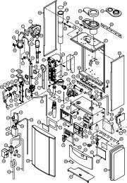
4 TECHNICAL INFORMATION4.1 Overview323334 35 36 3715 D.h.w. outlet pipe16 C.h. flow valve17 Condensate trap18 Main circuit drain valve19 Automatic air purger valve20 Pump21 Pump vent plug22 Modulation gas valve23 D.h.w. temperature probe NTCINSTALLATION313024 Primary circuit flow switch25 C.h. temperature probe NTC26 Three---way diverter valve27 Flame---detecting electrode28 Ignition electrodes29 Burner2930 Combustion chamber31 Primary heat exchanger2832 Fan33 Air switch pressure test points2734 Flue thermostat2635 Air pressure switch2536 Co ndensing heat exchanger242337 Safety thermostat38 D.h.w. flow switch39 C.h. pressure relief valve40 Modulation operator1741 Gas valve outlet pressure test point42 Gas valve inlet pressure test point1843 D.h.w. heat exchanger44 C.h. expansion tank45 By---pass valveFig. 4.12221201946 Venturi device47 Domestic water circuit filter11 Condensate drain pipe12 C.h. return valve13 Domestic cold water inlet valve14 Gas inlet valve48 D.h.w. flow limiter49 Flue outlet pipe50 Air intake pipe12
Technical information4.2 Main diagram (combi)50343649463231353743INSTALLATION27291928201741442548402224264738114239184523Fig. 4.21412 16 131513
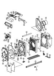
Technical information4.3 Main diagram (c.h. only)34365049INSTALLATION46323135372729192820174144252224401142391845Fig. 4.31412 1614
Technical information4.4 Hydraulic specificationskPa bar60 0.650 0.540 0.430 0.320 0.210 0.10 0.0Fig. 4.40 200 400 600 800 1000 1200 1400The hydraulic specifications in Fig. 4.4 representthe pressure (available head for the central heatingsystem) as a function of the flow rate.The load loss due to the boiler has already beensubtracted.Output with thermostat cocks shut offThe boiler is fitted with an automatic by---passvalve (45 on page 12), which protects the primaryheat exchanger.l/hIn case of excessive reduction or total blockage ofwater circulation in the central heating systemowing to closure of the thermostatic valves or systemcomponent cocks, the by---pass valve ensuresa minimum flow of water through the primaryheat exchanger.4.5 Expansion vesselNote: this boiler is designed for operation onlyin a sealed central heating systemThe height difference between the pressure reliefvalve <strong>and</strong> the highest point in the system may be7m at most.For greater differences, increase the pre---loadpressure in the expansion vessel (44 on page 12)<strong>and</strong> the system, when cold, by 0.1 bar for eachadditional 1m.Capacity l 6,0Pre---load pressureMaximum volume of waterin the system *Tab. 4.1* Where conditions are:kPabar1001,0l 132--- Average maximum temperature of the systemis 80°C--- Initial temperature when filling up the system is10°CFor systems with volumes greater than 132 l, anadditional expansion vessel must be provided.INSTALLATION15
Technical information4.6 Technical datamod. M96.24SM/...Central heatingMaximum flow temp. ° C 85Heat input (A)NominalMinimumkWBTU/hkWBTU/h25,085 29511,037 530Minimum flow temp. ° C 38Minimum return temp. ° C 30Maximum pressureMinimum pressurekPabarkPabar3003300,3INSTALLATIONUseful output G20MaximumMinimumMaximum condensingMinimum condensingkWBTU/hkWBTU/hkWBTU/hkWBTU/h24,683 97310,234 93626,690 75411,137 871Available head(in 1000 l/h)Seasonal efficiencyG20 (B)Seasonal efficiencyG30 G31 (B)Domestic hot waterkPabarb<strong>and</strong>%b<strong>and</strong>%250,25B87,7B86,9Maximum temperature ° C 55Useful output G30 G31MaximumMinimumMaximum condensingMinimum condensingkWBTU/hkWBTU/hkWBTU/hkWBTU/h23,780 89410,234 93626,690 75410,836 997Minimum temperature ° C 35Maximum pressureMinimum pressureFlow ratekPabarkPabar1 00010300,3minimum l/min 2,530° rise (C) l/min 12,135° rise (C) l/min 10,140° rise (C) l/min 8,7Gas supply pressuresGasNaturalG20ButaneG30PropaneG31Norm.Pambar2 000202 900293 70037MaxPambar2 500253 500354 50045Min.Pambar1 700172 000202 500251 mbar approximately equals 10 mm H 2 O(A) referred to the net calorific value at 15 ° C <strong>and</strong> 1013,25 mbarG 20 = 34,02 MJ/m 3, G 30 = 45,6 MJ/kg, G 31 = 46,4 MJ/kg(B) The value is used in the UK Government’s St<strong>and</strong>ard Assessment Procedure (SAP) for energy ratingof dwellings. The test data from which it has been calculated have been certified by a notified body.(C) Values subject to tolerance16
Technical informationGas pressures at the burnerGasMax.Min.IgnitionPambarPambarPambarNaturalG20108010,81501,56006,0ButaneG30280028,05505,5120012,01 mbar approximately equals 10 mm H 2 OGas rateGasNaturalG20m 3 /hButaneG30kg/hPropaneG31355035,57707,7130013,0PropaneG31kg/hMax. 2,65 1,97 1,94Min. 1,16 0,87 0,85InjectorsNatural G20 130Butane G30 75Propane G31 75Electrical DataVoltage V~ 230Frequency Hz 50Power consumption W 140Protection degreeIPX4DExternal fuse rating A 3Internal fuse rating A 1,6 TFlue designFlue pipe diameterCoaxial mm 60/100Twin split pipes mm 80Roof mm 80/125Nominal heat flow rate(A)(D)kW 25,0Exhaust temperature (D) ° C 90Smoke production (D) kg/h 68Flue gas figuresNominal heat input (A)(D) kW 25,0CO 2 content % 6,4O 2 content % 11,1CO content ppm 50Exhaust temperature (D) ° C 90Other specificationsHeight mm 803Width mm 400Depth mm 350Weight (dry) kg 42,5Water volume in the boiler(up to 1 bar)l (kg) 2,1INSTALLATION(D) Values refer to tests with a 1 m chimney working at the nominal heat input17
INSTALLATIONTechnical information4.7 Technical data mod.M96.28SM/... M96.28SR/...Heat input (A)NominalMinimumUseful output G20MaximumMinimumMaximum condensingMinimum condensingUseful output G30 G31MaximumMinimumMaximum condensingMinimum condensingkWBTU/hkWBTU/hkWBTU/hkWBTU/hkWBTU/hkWBTU/hkWBTU/hkWBTU/hkWBTU/hkWBTU/h29,098 94213,044 35328,396 48812,141 28430,7104 60213,244 96527,493 59912,141 28430,7104 60212,944 016Central heatingMaximum flow temp. ° C 85Minimum flow temp. ° C 38Minimum return temp. ° C 30Maximum pressureMinimum pressureAvailable head(in 1000 l/h)Seasonal efficiencyG20 (B)Seasonal efficiencyG30 G31 (B)kPabarkPabarkPabarb<strong>and</strong>%b<strong>and</strong>%Domestic hot water (M96.28SM/... only)3003300,3250,25B87,5B87,0Maximum temperature ° C 55Minimum temperature ° C 35Maximum pressureMinimum pressureFlow ratekPabarkPabar1 00010300,3minimum l/min 2,530° rise (C) l/min 14,035° rise (C) l/min 11,740° rise (C) l/min 10,1Gas supply pressuresGasNorm.MaxMin.PambarPambarPambarNaturalG202 000202 500251 70017ButaneG302 900293 500352 000201 mbar approximately equals 10 mm H 2 OPropaneG313 700374 500452 50025(A) referred to the net calorific value at 15 ° C <strong>and</strong> 1013,25 mbarG 20 = 34,02 MJ/m 3, G 30 = 45,6 MJ/kg, G 31 = 46,4 MJ/kg(B) The value is used in the UK Government’s St<strong>and</strong>ard Assessment Procedure (SAP) for energy ratingof dwellings. The test data from which it has been calculated have been certified by a notified body.(C) Values subject to tolerance18
Technical informationGas pressures at the burnerGasMax.Min.IgnitionPambarPambarPambarNaturalG20100010,01601,66006,0ButaneG30280028,05905,9120012,01 mbar approximately equals 10 mm H 2 OGas rateGasNaturalG20m 3 /hButaneG30kg/hPropaneG31360036,07707,7130013,0PropaneG31kg/hMax. 3,07 2,29 2,25Min. 1,28 1,03 1,01InjectorsNatural G20 130Butane G30 75Propane G31 75Electrical DataVoltage V~ 230Frequency Hz 50Power consumption W 160Protection degreeIPX4DExternal fuse rating A 3Internal fuse rating A 1,6 TFlue designFlue pipe diameterCoaxial mm 60/100Twin split pipes mm 80Roof mm 80/125Nominal heat flow rate(A)(D)kW 29,0Exhaust temperature (D) ° C 90Smoke production (D) kg/h 76Flue gas figuresNominal heat input (A)(D) kW 29,0CO 2 content % 6,8O 2 content % 10,7CO content ppm 75Exhaust temperature (D) ° C 90Other specificationsHeight mm 803Width mm 400Depth mm 350Weight (dry) kg 44,5Water volume in the boiler(up to 1 bar)l (kg) 2,2INSTALLATION(D) Values refer to tests with a 1 m chimney working at the nominal heat input19
5 GENERAL REQUIREMENTSINSTALLATION<strong>Biasi</strong> UK Ltd support the Benchmark initiative.Within the information pack, you will find aBenchmark Log Book. It is very important thatthis is completed correctly at the time of installation,commissioning<strong>and</strong> h<strong>and</strong> over to theuser.This appliance must be installed by a competentperson in accordance with the Gas Safety(installation & Use) Regulations.5.1 Related documentsThe installation of this appliance must be in accordancewith the relevant requirements of thecurrent Gas Safety (<strong>Installation</strong> & Use) Regulations,the Local Building Regulations, the currentI.E.E. Wiring Regulations, the Regulations <strong>and</strong>by---laws of the local water undertaking, <strong>and</strong> inScotl<strong>and</strong>, in accordance with the Building St<strong>and</strong>ards(Scotl<strong>and</strong>) Regulation. Health <strong>and</strong> safetydocument n° 635 ”Electricity at work regs.”.It should also be in accordance with the BritishSt<strong>and</strong>ard Codes of Practice:5.2 Location of applianceThe appliance may be installed in any room or internalspace, although particular attention isdrawn to the requirements of the current I.E.E. WiringRegulations, <strong>and</strong> in Scotl<strong>and</strong>, the electricalprovisions of the Building Regulations applicablein Scotl<strong>and</strong>, with respect to the installation of thecombined appliance in a room containing a bathor shower.Where a room---sealed appliance is installed ina room containing a bath or shower, any electricalswitch or appliance control, utilising mainselectricity should be so situated that it cannotbe touched by a person using the bath orshower.The location must permit the provision of an adequateflue <strong>and</strong> termination.For unusual locations special procedures may benecessary <strong>and</strong> BS 6798 gives detailed guidanceon this aspect.A compartment used to enclose the appliancemust be designed specifically for this purpose.This appliance is not suitable for external installation.5.3 Flue systemThe provision for satisfactory flue termination mustbe made as described in BS 5440 part 1.The appliance must be installed so that the flue terminalis exposed to external air.It must not be installed so that the terminal dischargesinto an other room or space as an outhouseor lean---to. It is important that the positionof the terminal allows a free passage of air acrossat all times.The terminal should be located with due regard forthe damage or discoloration that might occur tobuilding products in the vicinity.In cold <strong>and</strong>/or humid weather water vapour maycondense on leaving the flue terminal; the effect ofsuch ”steaming” must be considered.Pluming may easily occur at the terminal. Wherepossible, terminal position which could cause anuisance should be avoided.The minimum acceptable spacing from the terminalto obstructions <strong>and</strong> ventilation openings arespecified in Fig. 5.1.HIFig. 5.1FDJBCTerminal positionAMOENLKGGFmmA . Directly below a window or other opening . . . 300B . Below gutters, soil pipes or drain pipes . . . . . 75C . Below eaves . . . . . . . . . . . . . . . . . . . . . . . . . . . . 200D . Below balconies or car port roof . . . . . . . . . . . 650E . From vertical drain pipes <strong>and</strong> soil pipes . . . . . 75F . From internal or external corners . . . . . . . . . . . 300G . Above ground or balcony level . . . . . . . . . . . . 300H . From a surface facing a terminal . . . . . . . . . . . 600I . . From a terminal facing a terminal . . . . . . . . . 1 200J . From an opening in the car port(e.g. door, window) into dwelling . . . . . . . . . 1 20020rev. 17.09.93
General requirementsK . Vertically from a terminal in the same wall . 1 500L . Horizontally from a terminal in the same wall . 300Table follows in next pageM Above the roof pitch with roof slope lessthan or equal to 30° . . . . . . . . . . . . . . . . . . . . . . 600Above the roof pitch with roof slopemore than 30° . . . . . . . . . . . . . . . . . . . . . . . . . 1 000N . From wall face . . . . . . . . . . . . . . . . . . . . . . . . . . 600O . From an opening . . . . . . . . . . . . . . . . . . . . . . . . 300* specific manufacturer requirements5.4 Gas supplyThe Gas meter is connected to the service pipe bythe local gas region or a local gas region contractor.If the gas supply for the boiler serves otherappliances ensure that an adequate supply isavailable both to the boiler <strong>and</strong> the otherappliance when they are in use at the same time.Pipework must be of adequate size. Pipes of asmaller size than the boiler inlet connection shouldnot be used.<strong>Installation</strong> pipes should be fitted in accordancewith BS 6891 <strong>and</strong> the complete installation shouldbe tested for soundness.5.5 Air supplyThe room in which the boiler is installed does notrequire a purpose provided air vent.5.6 VentilationIf installed in a cupboard or compartment, it is notnecessary to provide additional ventilation forcooling for this particular product. However considerationmust be given to clearance requirementsfor maintenance (see section 6.2) <strong>and</strong>under no circumstances must stored articles be allowedto come into contact with the boiler or fluepipe.5.7 Condensate drainEnsure that the condensate discharge complieswith the national or local regulations in force.The condensate pipe must be fitted in accordancewith Building Regulations.Drainpipe material should be resistant to acid asthe condensate is slightly acid with a pH less than6.5.The boiler includes a trap (17 on page 12) that preventsthe combustion products entering the drain,however an additional trap with a seal of at least 75mm <strong>and</strong> an air break between the traps is required(Fig. 5.2).The length of the condensate pipe should be keptat minimum.To avoid condensate being trapped:--- the drainpipe should be run with a fall of at least2.5° (45 mm/m) away from the boiler;--- the number of bends <strong>and</strong> joints should be keptat minimum;--- the drainpipe should be adequately fixed topevent pipe sagging.If a part of the drainpipe runs externally this partshould pe kept as short as possible <strong>and</strong> protectedto reduce the risk of freezing.Fig. 5.2Condensate drain5.8 Water circulation (c.h.)Detailed recommendations are given in BS 6798<strong>and</strong> BS 5449; the following notes are given forgeneral guidance.PipeworkThe return temperature must not be lower of30 ° C.Copper tubing to BS EN 1057 is recommended forwater pipes. Jointing should be either with capillarysoldered or with compression fittings.Where possible pipes should have a gradient toensure air is carried naturally to air release points<strong>and</strong> water flows naturally to drain taps.The appliance has a built---in automatic air releasevalve, it should be ensured as far as possible thatthe appliance heat exchanger is not a natural collectingpoint for air.INSTALLATIONrev. 17.09.9321
General requirementsINSTALLATIONExcept where providing useful heat, pipes shouldbe insulated to prevent heat loss <strong>and</strong> to avoidfreezing.Particular attention should be paid to pipes passingthrough ventilated spaces in roofs <strong>and</strong> underfloors.By---passThe appliance includes an automatic by---passvalve which protects the main heat exchanger incase of reduced or interrupted water circulationthrough the heating system due to the closing ofthermostatic valves or cock---type valves within thesystem.The by---pass is calibrated to assure a minimumflow of 500---600 lts/hr through the main heat exchanger.If you are installing a system that includes thermostaticradiator valves (TRV) <strong>and</strong>/or small bore(8---10 mm) it may be necessary to fit an externalby---pass to facilitate correct operation of theboiler.Air release pointsThese must be fitted at all high points where air willnatural collect <strong>and</strong> must be sited to facilitate completefilling of the system.Expansion vesselThe appliance has an integral sealed expansionvessel to accommodate the increase of water volumewhen the system is heated.Refer to Tab. 4.1 on page 15 for its technical data.If the heating circuit has an unusually high watercontent, calculate the total expansion <strong>and</strong> add anadditional sealed expansion vessel with adequatecapacity.Mains water feed: central heatingThere must be no direct connection to the mainswater supply even through a non return valve,without the approval of the Local Water Authority.Mains water feed: hot water supplyThe domestic section of the boiler is designed towithst<strong>and</strong> an internal domestic water pressure of10 bar. Where it is likely that the mains domesticwater pressure may exceed 5 bar, it is possibledue to internal “water hammer” effects that thepressure within the domestic system can increaseto a level in excess of the 10 bar limit.In these circumstances it is therefore recommendedthat a 3 bar pressure reducing valve befitted to the incoming mains water supply <strong>and</strong> a22mini expansion vessel installed on the domesticcircuit.These devices will protect the boiler <strong>and</strong> the domesticsystem from damage due to excessive domesticwater pressure.FillingA method for initially filling the system <strong>and</strong> replacingwater lost during servicing must be provided<strong>and</strong> it must comply with local water authority regulations.The correct method is shown in Fig. 5.3.The temporary connection must be removedimmediately after filling.Supply pipe(cold water inlet)C.h. return pipeFig. 5.3rev. 17.09.93Control valveDouble check valveTemporaryconnectionControl valveThe installer should ensure that no leaks existeither inside the boiler or on the system as frequentfilling of the system could cause prematurescaling of the heat exchanger.5.9 Domestic waterThe domestic water installation must be in accordancewith the relevant recommendations of BS5546. Copper tubing to BS EN 1057 is recommendedfor water carrying pipework <strong>and</strong> must beuse for pipework carrying potable water.5.10 Water treatmentCentral heating circuitWhere a new boiler is fitted to a new system witheither plastic or copper pipes, it is important thesystem is fully flushed, on completion, to ensureflux residues, swarfs, oils <strong>and</strong> other installation debrisis removed.Where a new boiler is fitted to an existing system,it is important the debris from the existing systemis fully removed in order to ensure the efficiency ofthe new appliance is maintained.
General requirementsDetails on flushing procedure are given in the section7.4 of this <strong>manual</strong>.Domestic hot water circuit (scale protection)In areas where the water is ’hard’ (i.e. more than200 ppm total hardness as defined by BS 7593:1993 Table 2) it is recommended that a proprietaryscale---reducing device is fitted into the boiler coldsupply, within the requirements of the local watercompany.5.11 Electrical supplyWarning, this appliance must be earthed.External wiring to the appliance must be carriedout by a competent person <strong>and</strong> be in accordancewith the current I.E.E. Regulations <strong>and</strong> any localregulations which apply.The boiler is supplied for connection to a 230 V~50 Hz supply. The supply must be fused at 3A.The method of connection to the electricity supplymust facilitate complete electrical isolation of theappliance by the use of a fused double pole isolatorhaving a contact separation of at least 3 mmbetween poles or alternatively, by the use of a 3Afused three pin plug <strong>and</strong> unswitched shutteredsocket outlet both complying with BS 1363.The point of connection to the electricity supplymust be readily accessible <strong>and</strong> adjacent to theappliance except were the appliance is installed ina bathroom this must then be sited outside thebathroom.INSTALLATIONrev. 17.09.9323
INSTALLATION6 INSTALLATION6.1 WarningsThe use of gas appliances is subject tostatutory control; it is essential to observethe current regulations <strong>and</strong> laws in force(see also chapter 5).The appliance must discharge combustionproducts directly outside or into a suitable exhaustduct designed for this purpose.Combustion products must be dischargedusing original flue kits only, since they are integralparts of the boiler.For LPG, the appliance must also conform withthe requirements of the distributors <strong>and</strong> complywith current Regulations <strong>and</strong> laws in force.The safety relief valve <strong>and</strong> the condensatedrain must be connected to a suitable drain, ordischarge in a safe manner.The electrical wiring must conform with currentRegulations, in particular:--- the boiler must be earthed using the correctbonding clamp.--- a fused spur isolation switch, with a gap ofat least 3 mm between the contacts must beinstalled near to the boiler. Refer to section6.9 in this chapter for the electrical connections.In no circumstances will the manufacturerbe held responsible if the warnings <strong>and</strong> <strong>instructions</strong>contained in this <strong>manual</strong> have notbeen complied with.6.2 Precautions for installationFor the installation proceed as follows:--- The boiler must be fixed to a strong wall.--- The dimensions for the exhaust fume duct detailedin section 6.7 <strong>and</strong> the correct proceduresfor installing the duct, depicted in the instructionleaflet included with the flue kit, must becomplied with during installation.--- To allow maintenance procedures it is necessaryto leave the minimum gaps indicated inFig. 6.1.20025 50200Fig. 6.1 (all dimensions in mm)--- When installing the boiler in a cupboard, coveror alcove allow at least 50mm permanent clearancefrom the front face of the boiler. Also ensuresufficient clearance to allow free accessfor servicing <strong>and</strong> the lowering of the front controlpanel.--- If the boiler is installed outside, cover the applianceto protect it against the elements <strong>and</strong>add some special anti---freeze (neutralised) tothe c.h. system.--- Before installing the boiler on an existing c.h.system, flush it out thoroughly before fitting theboiler, so as to remove muddy deposits.--- It is advisable to equip the system with a sedimentfilter, or use a water---treatment product inthe circulating water.The latter option in particular, not only cleansout the system, but also has an anti---corrosiveeffect by promoting formation of a protectiveskin on metal surfaces <strong>and</strong> neutralising gasespresent in the water.We recommend the use of a suitable universalinhibitory to protect the c.h. system from corrosion.6.3 Installing the bracketPrecautionsBefore mounting the bracket, check that the dimensionsfor fitting the exhaust fume duct arecomplied with (refer to the leaflet included with theflue kit, packed separately).24
<strong>Installation</strong>Utilise the paper template supplied with the boilerto determine the fixing position for the bracket <strong>and</strong>boiler. Securely mount the bracket to the wallusing appropriate fixings suitable for the type ofwall construction <strong>and</strong> capable of supporting thetotal (wet) load. Refer to the weight given in thetechnical data tables specific for each model.6.4 Overall dimensions24580370060 60C.h.flow5019635C47ø80400115 14220031Electricconnectionarea100 2576552D.h.w.outlet*736465200ø80Bø10016Coldwaterinlet C.h.Gas * returnA190A, B <strong>and</strong> C350Condensate drainconnectionareaA --- air intake/flue outlet pipe (co---axial)B --- flue outlet pipe ø 80 mm (twin kit)C --- air intake pipe ø 80 mm (twin kit)* not present on c.h. only boilersFig. 6.2 (all dimensions in mm)Boiler front6.5 JointsFunctionsGas, c.h. return, c.h. flow ø 22D.c.w. inlet * ø 15D.h.w. outlet * ø 15Pressure relief valve ø 15Condensate drain* not present on c.h. only boilersTab. 6.1 (sizes in mm o.d.)6.6 Mounting the boilerPipe sizes (o.d)ø 25 (plastic)1 Take the protective caps off the boiler pipework.2 Thoroughly clean the connections.3 Mount the boiler on its bracket.4 Fix the c.h. valves A <strong>and</strong> gas cock B (¾”) to theboiler using the ¾” gaskets (Fig. 6.3)5 Fix the ø 22 mm pipes C (c.h. circuit) to the c.h.valves A <strong>and</strong> the ø 22 mm pipe D (gas) to thecock B using the ¾” gaskets.6 Repeat the above procedure for the d.c.w. inletutilising the ½” cold water inlet valve E, the ø 15mm copper tail F with its connection nut <strong>and</strong>two ½” gaskets.7 Fix the ø 15 mm copper tail G with the ½” connectionnut <strong>and</strong> a ½” gasket.AFig. 6.3BECGADFCINSTALLATION25
<strong>Installation</strong>INSTALLATION8 Connect the pipe H (Fig. 6.4) from the pressurerelief valve to the safety discharge pipework.9 Fit the condensate drain 11 (Fig. 6.4) in the airbrake connected to the drainage pipework.See also section 5.7 in this <strong>manual</strong>.Fig. 6.4H116.7 Fitting the flue systemRefer to the assembly <strong>instructions</strong> contained withinthe chosen flue kit packaging for the correct assembly<strong>and</strong> installation.In general, it has to be taken in consideration thatthe horizontal sections of the flue pipe must havean horizontal sloping not less than 1.5 deg. (25mm per metre) towards the boiler.In the st<strong>and</strong>ard horizontal flue kit (Fig. 6.5A) theflue pipe is angled within the air duct therefore theair duct must be horizontally installed.If one or more extensions have to be used theymust be adequately supported so that there is nosag in the flue pipe <strong>and</strong> a minimum fall of 1,5 deg.(25 mm per metre) over the whole length towardsthe boiler is ensured.6.8 Choice of flueThe following flue kits are available for connectingto the boiler:St<strong>and</strong>ard horizontal flue kit (Fig. 6.5A)Co---axial 60/100mm --- nominal length 1mThis kit is normally supplied with the boiler <strong>and</strong> canbe fitted to allow discharge to the rear or eitherside of the boiler via the flanged boiler adapterelbow. Minimum length required is 0.3 m. Maximumequivalent length of 2,7 metres can beachieved utilising extensions. This flue system canonly be used to discharge horizontally, it is not designedto enable termination in the vertical plane.Vertical kit with 90° elbow (Fig. 6.5B)Co---axial 60/100 mmSupplied with a straight flanged adapter a co---axial elbow <strong>and</strong> a co---axial pipe with terminal, thiskit allows for a vertical rise of 0,5 m from the boiler.In all circumstances the flue terminal must dischargehorizontally <strong>and</strong> the equivalent flue lengthmust not exceed 2,7 metres.Elbows 45° & 90° (Fig. 6.5C)Co---axial 60/100mm.Elbow kits enable the st<strong>and</strong>ard flue kits to be offsetto overcome obstructions or ensure the correctclearances for the flue terminal. Each elbow usedin addition to the st<strong>and</strong>ard flanged elbow reducesthe overall acceptable length of the flue system asfollows:45° reduce length by 0.5 m.90° reduce length by 1 m.ø 60/100Fig. 6.590° =--- 1mTwin pipe kits ø 80 mm (Fig. 6.6)BMin = 0,3 mMax = 2,7 mACø 60/10045° =--- 0,5mVarious twin (split) pipes kits <strong>and</strong> optional accessories(elbows) are available to assist in the terminationof the flue where the boiler is installed ina location remote to an outside wall.These kits allow for separation of the air supplypipe from the pipe that discharges the exhaust26
<strong>Installation</strong>gasses. Consequently it is possible to extend theflue system to a greater distance than that providedby the st<strong>and</strong>ard horizontal co---axial flue.If either an additional 45° or 90° accessory elbowis used then the maximum permissible length ofeither pipe must be reduced by 0.90 m or 1,65 mrespectively.Fig. 6.690° =--- 1,65 m45° =--- 0,90 mTwo restrictors with different size are suppliedwith the twin pipe kit <strong>and</strong> have to be installedbetween the boiler <strong>and</strong> the air intake adapter(Fig. 6.7).Air intake adapterRestrictorGasketThis kit allows vertical termination of the flue pipethrough the roof. The kit is 1.2 m in length. Extensionpieces (Co---axial) are also available which allowsthe flue system to be extended to a totaloverall maximum permissible length.Optional 45° <strong>and</strong> 90° elbows can be used to offsetthe flue route.Each additional elbow reduces the overall acceptablelength of the flue system as follows:45° reduce length by 0.5 m.90° reduce length by 1 m.Fig. 6.8max = 8.5 m6.9 Electrical connections90° =--- 1m45° =--- 0,5mINSTALLATIONConnection to the electricity supply1 Remove the front panel of the case (see thesection 9.2 in this <strong>manual</strong>).2 Remove the screws I <strong>and</strong> J (Fig. 6.9).3 Loosen the screws K.Fig. 6.7For the correct use of the restrictors with twinpipes refer to Tab. 6.2.Equivalent length(air duct + flue duct)Between 1 <strong>and</strong> 15 mMore than 15 m up to 30 mRestrictorø 50 mmø 55 mmTab. 6.2Vertical--- roof kit (Fig. 6.8)27
<strong>Installation</strong>To fused spurisolation switchLNM321Power supplyterminal blockTo the externalcontrol deviceTo the fused spurisolation switchExternal controlsterminal blockFig. 6.128 Connect the room thermostat between terminals1 <strong>and</strong> 3 as shown in Fig. 6.13.Do not connect live wires to terminals towhich the room thermostat must be connected.Room thermostatTLPower supplyterminal blockNFig. 6.146.10 External frost protection10 Connect the frost thermostat between terminals1 <strong>and</strong> 2 as shown in Fig. 6.15.Do not connect live wires to terminals towhich the room thermostat must be connected.Frost thermostatRoom thermostatLNINSTALLATION321External controlsterminal blockTTFig. 6.139 Route the electrical supply flexible cord <strong>and</strong>the external control flexible cord as illustratedin Fig. 6.14.Lock the flexible cords in place with the flexiblecord clampsFig. 6.15321Power supplyterminal blockExternal controlsterminal block6.11 Connecting a M96.28SR/...system boiler to a cylinderTwo schematic wiring diagrams are given in thissection showing two possible ways to connect anexternal programmer to a mid---position divertervalve to provide independent timed <strong>and</strong> thermostaticcontrol of heating <strong>and</strong> hot water.In both diagrams the earth wires are not shown forclarity. Earth wiring must be fitted as necessary.29
<strong>Installation</strong>LRoom thermostatINSTALLATIONNMAINS230V a.c.Switched 3 Amp fused,spurValve colour keyBR --- BrownBL --- BlueGR --- GreyOR --- OrangeProgrammerCylinderthermostatBLGRBRORRelayRemove roomthermostat linkMid--- positiondiverter valveL NPower supplyterminal block123M96.28SR/...External controlterminal blockFig. 6.16 --- relay controlled boilerLRoom thermostatNMAINS230V a.c.Switched 3 Amp fused,spurProgrammerCylinderthermostatL NPower supplyterminal blockValve colour keyBR --- BrownBL --- BlueGR --- GreyOR --- OrangeBLGRBRORMid--- positiondiverter valveDo notremove roomthermostat link123M96.28SR/...External controlterminal blockFig. 6.17 --- directly controlled boiler30
7 COMMISSIONINGEnsure that the Benchmark logbook is satisfactorilycompleted during the commissioningprocess.4 Gradually open stopcock at the filling pointconnection to the c.h. system until water isheard to flow; do not open fully.7.1 Electrical installationPreliminary electrical system checks to ensureelectrical safety shall be carried out by a competentperson. i.e. polarity, earth continuity, resistanceto earth <strong>and</strong> short circuit.If a fault has occurred on the appliance the fault findingprocedure should be followed as specified in theservice <strong>manual</strong>.7.2 Gas supply installation1 Inspect the entire installation including the gasmeter, test for soundness <strong>and</strong> purge, all as describedin BS 6891;2 Open the gas cock 14 (Fig. 7.1) on theappliance <strong>and</strong> check the gas connector on theappliance for leaks.Fig. 7.114 13Open position7.3 Filling the d.h.w. system1 Close all hot water draw---off taps.2 Open the cold water inlet valve 13 (Fig. 7.1).3 Slowly open each draw---off tap <strong>and</strong> close itonly when clear water, free of bubbles, flowsout.7.4 Initial filling of the system1 Open the c.h. flow <strong>and</strong> return valves.2 Remove the front panel of the case (see thesection 9.2 in this <strong>manual</strong>.3 Unscrew the cap on the automatic air purgervalve19 (Fig. 7.2) one full turn <strong>and</strong> leave openpermanently.1921Fig. 7.25 Open each radiator air vent starting at thelowest point of the system <strong>and</strong> close it onlywhen clear water, free of bubbles, flows out.6 Purge the air from the pump by unscrewing thepump plug 21 (Fig. 7.2); release the pumpshaft by turning in the direction indicated bythe arrow on the information plate.7 Replace the pump plug.8 Continue filling the system. The actual readingshould ideally be 1,3 bar <strong>and</strong> not less than 0,3bar.9 Close all air release valves on the c.h. system.10 Inspect the boiler <strong>and</strong> the system for watersoundness <strong>and</strong> remedy any leaks discovered.11 Cold flush the system to remove any loose particles<strong>and</strong> any system debris before starting theboiler for the first timeThe flushing procedure must be in line withBS7593 Treatment of Water in d.h.w. c.h. Systems.When the installation <strong>and</strong> second filling arecompleted turn on the c.h. system <strong>and</strong> run ituntil the temperature has reached the boileroperating temperature. The system must thenbe immediately flushed through.This procedure must be repeated twice more.During this operation we highly recommendthe use of a c.h. flushing detergent in the quantitiesas specified by the appropriate manufacturer,whose function it is to dissolve anyforeign matter which may be in the system.INSTALLATION31
CommissioningThe above operation could save the invalidationof your boilers guarantee <strong>and</strong> will also preventproblems which you may experience inthe future if an inhibitory is not used.10 8 7 6INSTALLATION7.5 Condensate pipe <strong>and</strong> trapsThe full length of the condensate pipe should becheck for leaks.The boiler has a built---in condensate trap providedwith a ball valve that prevents the escape ofcombustion products when the trap is empty.It is however recommended that any other trapin the drain system is correctly filled with waterbefore to run the boiler.7.6 Lighting the boilerSome products incorporate an anti cycling timedelay. It is normal when first switching the boiler onfor the boiler to operate on heating for a few secondsthen switch off. After 3---4 minutes haselapsed the boiler will then re ignite <strong>and</strong> operateperfectly normally. The ignition delay cycle doesnot prevent normal operation of the boiler to provided.h.w..If external controls are fitted (e. g. Timeclock, roomthermostat) ensure they ”call for heat”.1 Turn on the electricity supply to the boiler,switching on the fused spur isolation switch.The appliance operation light 10 will flashevery 4 seconds.2 Turn the function selector 8 as in Fig. 7.3(combi) or Fig. 7.4 (c.h. only). The applianceoperation light 10 will flash every 2 seconds.Fig. 7.310 8 7 6Fig. 7.4The boiler will now go through an ignition sequence<strong>and</strong> the burner will light.If during the ignition attempt period the boiler failsto light, the full sequence control p.c.b. will go tolockout <strong>and</strong> the lock---out signal lamp 6 will appear.To reset the boiler press <strong>and</strong> release the boiler resetbutton 7 (Fig. 7.3).7.7 Checking the gas pressure atthe burnerThis boiler has been tested to the highest qualitycontrol st<strong>and</strong>ards.The maximum <strong>and</strong> minimum gas pressures arealready set during this quality control processhowever the checking procedure must be followedto ensure maximum operating efficiencyfrom the boiler.1 Remove the front panel of the case (see section9.2 in this <strong>manual</strong>).2 Loosen the internal screw 41 (Fig. 7.5) on theOutlet Pressure Test Point of the Gas Valve <strong>and</strong>connect a pressure gauge using a suitablehose.3 Set the d.h.w. <strong>and</strong> c.h. temperature controlknobs to their maximum position.4 Switch on the boiler <strong>and</strong> open at least one hotwater tap fully.5 Check the maximum gas pressure <strong>and</strong> comparethe value on the gauge with the value indicatedin the sections 4.6 or 4.7 (gas pressures32
Commissioningat the burner), accordingly with the model ofboiler installed.6 Check the maximum gas flow at the gas meter<strong>and</strong> compare the value indicated in the sections4.6 or 4.7 (gas rate), accordingly with themodel of boiler installed.7 Switch off the boiler.8 Disconnect the gas modulator coil by removingthe electrical connector A (Fig. 7.5).41 Agas pressure adjustment procedure is given inthe Gas Valve section of the service <strong>manual</strong>. Ifmaximum <strong>and</strong>/or minimum gas pressures areadjusted then the ignition gas pressure mustbe checked <strong>and</strong> adjusted if necessary.Important: after the gas pressure checks <strong>and</strong>any adjustment operations, all of the test points<strong>and</strong> adjustment devices must be sealed.7.8 Adjusting the burner ignition1 Turn off the boiler by means of the fused spurisolation switch provided adjacent to the appliance.2 Make sure that the function selector 8 is set tothe position in Fig. 7.6 <strong>and</strong> that the timer selectorswitch <strong>and</strong> room thermostat, if fitted, is setto “dem<strong>and</strong> heat”.INSTALLATIONFig. 7.59 Switch on the boiler.10 Check the minimum gas pressure <strong>and</strong> comparethe value on the gauge with the value indicatedin the sections 4.6 or 4.7 (gas pressuresat the burner), accordingly with the model ofboiler installed.11 Switch off the boiler <strong>and</strong> re---connect the electricalconnector A to the modulator coil.12 Access the main control panel (see section 6.9,follow steps 2 --- 5)13 Switch on the boiler.14 Check the ignition gas pressure by settingdip---switch ”3” (Fig. 7.8) to the OFF position.Compare the value on the gauge with the valueindicated in the sections 4.6 or 4.7 (gas pressuresat the burner), accordingly with themodel of boiler installed.If the ignition gas pressure is not set correctlysee section 7.8 in this <strong>manual</strong> for the adjustmentprocedure. If ignition gas pressure is correctswitch dip---switch ”3” to the ON position.15 Switch off the boiler, turn off the hot water tap(s)<strong>and</strong> disconnect the pressure gauge.If the maximum <strong>and</strong> minimum gas pressuresmeasured above are not in accordance with thetechnical data (sections 4.6 or 4.7) then adjustmentwill be necessary. A full explanation of theFig. 7.63 Unscrew the gas valve’s outlet pressure testpoint 41 (Fig. 7.5) <strong>and</strong> connect a pressuregauge.4 Loosen the screws B <strong>and</strong> remove the servicepanel (Fig. 7.7).BFig. 7.75 Turn on the boiler.6 Check that the boiler lights up uniformly <strong>and</strong>adjust the ignition gas pressure, if necessary.33
CommissioningINSTALLATIONTo adjust the ignition gas pressure, set dip---switch”3” (Fig. 7.8) to the OFF position <strong>and</strong> adjust potentiometermarked “ACC” with a screwdriver untilcorrect ignition gas pressure is obtained.Fig. 7.81+ACCON2 3OFFRISCRefer to the table gas pressures at the burner in thesections 4.6 or 4.7 for appropriate value.7 Having finished this procedure, reset dip---switch ”3” to the ON position.7.9 Adjustment of useful c.h.outputIf the burner function selector (dipswitch number4 on the main P.C.B.) is set to the ’ON’ position itwill activate the re---ignition delay period of approximately4 minutes. When dipswitch number 4is set to the ’OFF’ position there will be approximately30 seconds re---ignition delay period.Whilst checking or adjusting the c.h. output, <strong>and</strong>fault finding on the boiler it may be necessary toswitch the re---ignition delay mechanism (dipswitch4) to the ’OFF’ position.Refer to the diagrams shown in Fig. 7.9, Fig. 7.10or Fig. 7.11 <strong>and</strong> select the correct central heatingoutput gas pressure to meet with the central heatingsystem requirements.With the boiler operating in c.h. mode, use a suitablescrewdriver to turn the adjustment potentiometermarked “RISC” (Fig. 7.8).Rotating the potentiometer anti---clockwise reducesthe maximum supply current to the gasmodulator device, <strong>and</strong> thus reduces the gas pressureto the burner.+4kWNatural (G20)2927252321191715131191 2 3 4 5 6 7 8 9 10 11M96.24SM/...mbarM96.28SM/... M96.28SR/...Fig. 7.9kWButane (G30)282624222018161412105 7 9 11 13 15 17 19 21 23 25 27 29M96.24SM/...mbarM96.28SM/... M96.28SR/...Fig. 7.1034
CommissioningkWPropane (G31)2927252321191715131197 10 13 16 19 22 25 28 31 34 37M96.24SM/...mbarM96.28SM/... M96.28SR/...Fig. 7.117.10 Checking the ignition deviceWith the burner on high flame close the gas cock.About 10 seconds after, the lock---out signal lamp6 (Fig. 1.3 on page 2) must appear.To reset the boiler press <strong>and</strong> release the boilerreset button 7 (Fig. 1.3 on page 2).7.11 Checking the flue systemThe flue system should be visually checked forsoundness. Check all clamps, gaskets <strong>and</strong> fixingsare secure <strong>and</strong> tight.Ensure that the flue terminal is sited correctly in accordancewith the flue fitting <strong>instructions</strong> <strong>and</strong>Fig. 5.1 on page 20 of this <strong>manual</strong>.To carry out a combustion check refer to the <strong>instructions</strong>given in the section 9.5 of this <strong>manual</strong>.Reference figures are given in the sections 4.6 or4.7 of this <strong>manual</strong> (Flue gas figures).7.12 Checking the condensatedrain pipeCheck the soundness <strong>and</strong> integrity of the condensatedrain pipe.Verify the cleaness <strong>and</strong> correct filling of the condensatetraps.7.13 Instructing the userH<strong>and</strong> over this combined <strong>User</strong> & <strong>Installation</strong> <strong>manual</strong><strong>and</strong> the Service <strong>manual</strong> to the end user <strong>and</strong> explainhow to use the unit in both c.h. <strong>and</strong> d.h.w.modes.Take the <strong>User</strong> step by step through the lighting <strong>instructions</strong>.Show the <strong>User</strong> how to switch off the appliancequickly <strong>and</strong> indicate the position of the electricsupply isolator.Explain the proper use <strong>and</strong> adjustment of all systemcontrols; this will ensure the greatest possiblefuel economy.Explain the function <strong>and</strong> use of the function selector.Explain <strong>and</strong> demonstrate the function of time <strong>and</strong>temperature controls (if fitted).Explain how to turn off the appliance for both short<strong>and</strong> long periods <strong>and</strong> advise on the precautionsnecessary to prevent damage should theappliance be inoperative when freezing conditionsmay occur.Fill in the details required on the Boiler GuaranteeCertificate <strong>and</strong> h<strong>and</strong> to the <strong>User</strong> advising them toreturn the correct section for boiler Guarantee registration.Finally, advise the <strong>User</strong> that, for continued safe<strong>and</strong> efficient operation, the appliance must be servicedby a competent person at least once a year.INSTALLATION35
MAINTENANCE8 GAS CONVERSION8.1 WarningsProcedures to adapt the boiler to the type ofgas available must be carried out by a competent<strong>and</strong> responsible person.Components used to adapt it to the type of gasavailable must be genuine parts only.8.2 Procedures1 Check that the gas cock (14 in Fig. 9.3) fittedunder the boiler is turned off <strong>and</strong> the applianceis is switched off at the mains isolating spur.2 Remove the front <strong>and</strong> side panels of the case(see the section General access <strong>and</strong> emptyinghydraulic circuits in the service <strong>manual</strong>).3 Take off the lid of the sealed chamber.4 Take the front panel of the combustionchamber off <strong>and</strong> remove the burner (29 onpage 12). See section Ignition <strong>and</strong> detectionelectrodes in the service <strong>manual</strong> for detailed <strong>instructions</strong>.5 Carry out the conversion for the type of gas, replacingthe burner injectors correctly.6 Re---assemble the burner, the front panel of thecombustion chamber <strong>and</strong> the lid of the sealedchamber.7 Extract the control panel as explained in thesection 6.9 of this <strong>manual</strong>.8 Loosen the screws C <strong>and</strong> remove the servicepanel (Fig. 8.1).C9 set correctly the dip---switch ”2” to the correctposition (Fig. 8.2) in accordance with the followingtable.Gas supply Position of dip---switch 2Natural gasL.P.G.Fig. 8.2OnOffNatural gasON1 2 3 4OFF1L.P.G.2ONOFF3 410 Calibrate the gas valve according to the <strong>instructions</strong>given in the service <strong>manual</strong>, sectionModulating gas valve --- Adjustment.11 Set the correct gas pressure for central heatingoutput required, see section 7.9 in this <strong>manual</strong>.12 Stick on the inside of the left h<strong>and</strong> side paneladjacent to the data badge the self---adhesivelabel (included with the conversion kit) indicatingthe type of gas, <strong>and</strong> the gas pressures towhich the appliance has been set.13 Replace the service panel, the front <strong>and</strong> sidepanels of the case.Fig. 8.136
9 MAINTENANCE9.1 WarningsThe procedures detailed in this chapter mustbe carried out only by a professionallyqualified person. Thus you are advised tocontact an Authorised Service Agent.For efficient <strong>and</strong> continuous operation of theboiler you are advised to have, at least once ayear, maintenance <strong>and</strong> cleaning done by anApproved Service engineer.Isolate the appliance from the electricitysupply by turning off the fused spur isolationswitch adjacent to the appliance <strong>and</strong> turn offthe gas cock, before carrying out any procedures,whatsoever, for cleaning, maintenance,opening or dismantling boiler panels.9.2 Dismantling the externalpanelsFront panel1 Loosen the three screws A (Fig. 9.1).2 Lift <strong>and</strong> remove the panel.Air--- Flue exhaustSampling pointsA3 Loosen the screws B. Bring the bottom of thepanels away from the boiler <strong>and</strong> lift them, freeingthem from the top hooks (Fig. 9.2).Fig. 9.2B9.3 Emptying the d.h.w. system(combi)1 Turn off the d.c.w. inlet isolating valve (13 inFig. 9.3) <strong>and</strong> turn on the hot water taps <strong>and</strong> anydrain cocks.Closed positionMAINTENANCE1216Fig. 9.313149.4 Emptying the c.h. systemFig. 9.11 Close the c.h. isolating valves (12 <strong>and</strong> 16 inFig. 9.3).2 Open the central heating drain cock (18 inFig. 9.4).Side panels37
MaintenanceMAINTENANCE3 A small quantity of water will remain in thed.h.w. heat exchanger after draining. If theboiler is being drained to prevent freezing, thed.h.w. heat exchanger must be removed <strong>and</strong>inverted to drain fully or an antifreeze solutionadded.Fig. 9.49.5 Combustion analysis check18If it is necessary to carry out a combustion analysisremove the plugs indicated in Fig. 9.1.Reference figures are given in the sections 4.6 or4.7 of this <strong>manual</strong> (Flue gas figures).9.6 Cleaning the primary heatexchanger1 Take off the front of the case.2 Take off the removable front of the air---tightchamber <strong>and</strong> the front panel of the combustionchamber.If you notice dirt on the fins of the primary heat exchanger(31 on page 12):3 cover the sloping surfaces of the burner (29 onpage 12) entirely in a protective layer (sheets ofnewspaper or similar).4 Brush out the primary heat exchanger (31 onpage 12) with a bristle paintbrush.NOTE --- When removing the airtight chambercover it is not necessary to remove the screws locatedat the top edge on either side.9.7 Checking the pressurisationin the expansion vesselEmpty the central heating system as described insection 9.4 of this chapter <strong>and</strong> check that the pressurein the expansion vessel is not less than 1 bar.See also section 4.5 page 15 of this <strong>manual</strong>.If the pressure is lower, take steps to correct thepressure level.9.8 Cleaning the burnerThe sloping <strong>and</strong> multi---gas type burner (29 onpage 12) does not need special maintenance, butit is sufficient to dust it with a bristle paintbrush.To reach the burner:1 Take off the front of the case.2 Take off the removable front of the air---tightchamber <strong>and</strong> the front panel of the combustionchamber.3 Brush out the burner with a bristle paintbrush.NOTE --- When removing the airtight chambercover it is not necessary to remove the screws locatedat the top edge on either side.9.9 Checking the flueHave the integrity of the flue outlet pipe (49 onpage 13) air intake pipe (50 on page 13), checkedperiodically, the venturi device* (46 on page 13)cleaned <strong>and</strong> the efficiency of the flue safety circuitchecked at least once a year.* For details see the section Fan, venturi device<strong>and</strong> air pressure switch in the service <strong>manual</strong>.For all the above maintenance operations it is advisableto call an approved Service Engineer.9.10 Drain pipe inspectionCheck the soundness <strong>and</strong> integrity of the condensatedrain pipe.Verify the cleaness <strong>and</strong> correct filling of the condensatetraps.9.11 Visual inspection ofapplianceVisually inspect all water joints, seals <strong>and</strong> connectionsfor any evidence of leakage <strong>and</strong> retighten,grease or replace them as necessary.9.12 Gas pressures <strong>and</strong> soundnessCheck appliance for gas soundness. Recheck operationalpressures <strong>and</strong> adjust as necessary asdescribed in section 7.7 page 32 of this <strong>manual</strong>.38
*1796211131*17962.1113.1 3804 44A5 UK<strong>Biasi</strong> U.K. LtdUnit 31/33, Planetary RoadIndustrial Estate, Neachells LaneWillenhall, Wolverhampton WV 13 3XBTechnical helpline: 01902 304 400Web site: www.biasi.co.uk