Installation And Servicing Instructions - Heatingspares247.com
Installation And Servicing Instructions - Heatingspares247.com
Installation And Servicing Instructions - Heatingspares247.com
- No tags were found...

Create successful ePaper yourself
Turn your PDF publications into a flip-book with our unique Google optimized e-Paper software.
WD209/1/2000The Keston Celsius 25 & 25PCONTENTSSectionDescription1 GENERAL INSTRUCTION1.1 Description1.2 Boiler Schematic1.3 Related Documents1.4 Performance Data1.5 Optional Accessories2 BOILER LOCATION2.1 Dimensions & Minimum Clearances2.2 Service Connections2.3 Position2.4 Electrical2.5 Boiler Size Selection2.6 Gas Supply2.7 Water Systems2.8 Flue System2.9 Air Supply2.10 Compartment <strong>Installation</strong>2.11 Condensate Drainage3 INSTALLATION OF THE BOILER3.1 Wall Mounting Bracket3.2 Mounting The Boiler3.3 Assembly Practice3.4 Installing Flue <strong>And</strong> Air Pipes3.5 Condensate Drainage3.6 Water System3.7 Gas Supply3.8 Electrical Supply3.9 Exchanging A Boiler4 COMMISSIONING OF THE BOILER4.1 Initial Flushing4.2 Gas Supply4.3 Electrical <strong>Installation</strong>4.4 LPG Gas4.5 Initial Firing4.6 Hot Flushing4.7 Checking The Gas PressurePage : i
WD209/1/2000The Keston Celsius 25 & 25P4.8 Timing The Gas Meter4.9 Combustion Testing4.10 Handing Over To The User5 FAULT FINDING5.1 Electrical Control Sequence5.2 Fault Finding Flow Chart - General5.3 Fault Finding Flow Chart - Detailed5.4 Functional Flow Wiring Diagram5.5 Electrical Wiring Diagram5.6 Illustrated Wiring Diagram5.7 Exploded Assembly Diagrams6 SERVICING6.1 Pre Service Checks6.2 Recommended Routine Service7 REPLACEMENT OF PARTS7.0 General7.1 Precautions7.2 Access7.3 Replacement Procedure7.4 Electrical Components7.5 Spark Ignition/Flame Detection Electrode7.6 Burner7.7 Heat Exchanger7.8 Condensate Trap7.9 Pump8 SPARE PARTS LISTINGSPage : ii
WD209/1/2000 Chapter 1 : General Instruction The Keston Celsius 25 & 25P1. GENERAL INSTRUCTION1.1 DESCRIPTIONThe Celsius 25 is unique in its concept and design. It comprises a high efficiencystainless steel heat exchanger coupled with a low emissions burner to deliver ultra highefficiency condensing mode operation within a compact wall hung cabinet. The unitautomatically adjusts gas and air rate according to demand to give an output in the rangeof 7.0kW to 25.2kW (natural gas model). The integral standard UPS Grundfos pump isautomatically controlled across the three speeds to best match water flow rate to heatoutput & further increase appliance efficiency. While the application for which the Celsius25 was designed is the same as those which other boilers are used, the Keston Celsius25 has the added advantage of very high efficiency, and small diameter plastic flue whichcan be extended to 20 metres horizontally or vertically.The Keston Celsius 25 uses a variable speed combustion blower to deliver a premix ofgas and air to a downward firing burner in a high efficiency, single pass heat exchanger.The flue system is room sealed and fan powered. The ignition is direct spark and fullyautomatic. The boiler housing is not waterproof and should be installed in a positionwhere it will always be dry. Combustion air is drawn from the cabinet which is connectedto outside atmosphere via a small diameter plastic intake pipe. The cabinet thereforeremains under negative pressure at all times the boiler is operating.The boiler is suitable for connection to open vented or, preferably, sealed systems.The boiler heat exchanger is made from highly corrosion resistant stainless steel incorrugated pipe form which provides massive surface area within a compact dimension.The hot combustion gases from the down firing burner pass around the stainless steelpipes imparting heat into the system water. The integral standard 3 speed Grundfospump within the appliance cabinet ensures the heat exchanger receives correct waterflow when firing. The Celsius 25 is not a high water content boiler and does not containthe metal mass, or water volume, of a cast iron or steel boiler. This boiler is of low massand low water content and therefore responds faster when there Is a call for heat. TheCelsius 25 features full user diagnostics, integral frost protection thermostat, automaticpump and fan exercise in periods of inactivity, anti cycle control, dry fire protection andconnections for remote lockout and run monitoring.1.2 BOILER SCHEMATICAir is drawn into the boiler through a 50 mm muPVC (BS5255) plastic pipe. Gas is mixedwith combustion air at the inlet to the fan. The gas flow is automatically regulated by thegas valve according to the air flow generated by the fan. The gas and air are thoroughlymixed in the blower and fed into the burner located at the top end of the heat exchangermodule. The gas and air mixture is ignited by a direct spark ignition control system andburns with a blue flame just off the surface of the burner. As the hot products ofcombustion pass downwards, they are cooled by exchanging heat with the circulatingwater which enters the heat exchanger at the bottom of the heat exchanger. The optimumheat input is detected by monitoring flow and return temperatures and is adjusted bycontrolling the speed of the fan. The optimum pump speed is also detected andautomatically selected by the boiler.When the return water temperature is below 55 O C, part of the water vapour in thecombustion products will condense inside the heat exchanger, thus increasing the boilerefficiency further by releasing the latent heat of condensation. This condensate falls tothe bottom of the heat exchanger where it is separated from the flue gases and exits fromthe boiler through the condensate drain. Any condensate formed in the flue runs backdown the flueway and is drained at the base of the flue connection to the heat exchangeror drain points within the flue.<strong>Installation</strong> & <strong>Servicing</strong> <strong>Instructions</strong> Page : 1
WD209/1/2000 Chapter 1 : General Instruction The Keston Celsius 25 & 25PFig. 1.2 - Boiler LayoutThe condensate is very slightly acidic (about the same acidity as vinegar) and should bepiped in a plastic pipe. It is not harmful to the waste disposal system and may bedisposed of as normal waste water.The flue gases are piped in a 50 mm muPVC (BS5255) plastic pipe to the outside. Thetemperature of the flue gases are usually around 5 o C above the temperature of the returnwater. The flue pipe should be terminated outside the building from where they cannotre-enter the building or any other adjacent building.The heating level may be controlled by room thermostats, hot water calorifierthermostats, programmer time clocks and energy management systems.The Celsius 25 features an integral frost protection function which will fire the boiler,regardless of the external controls, should the boiler temperature fall below 4 O C. Theboiler will continue to fire until the boiler flow temperature exceeds 15 O C. This is to avoiddamage to the boiler through freezing of boiler water.The Celsius 25 features an integral pump/fan exercise function which will run the fan andpump, without firing the boiler, for 5 seconds in the event the boiler is on standby for inexcess of 24 hours without firing. This is to help prevent seizing of fan and/or pump dueto long periods of inactivity.1.3 RELATED DOCUMENTSThe Keston Celsius 25 Condensing Boiler must be installed in accordance with thecurrent issue of the Gas Safety (<strong>Installation</strong> and Use) Regulations 1996, current IEEWiring Regulations, Building Regulations, Building Standards (Scotland) Consolidation,and the Bye Laws of the local Water Undertaking.In addition, due account must be taken to the following Codes Of Practice:BS 6891 : Gas SuppliesBS 6798 : <strong>Installation</strong> Central Heating BoilersBS 5449 : <strong>Installation</strong> Pumped Central HeatingBS 5546 : <strong>Installation</strong> Domestic Hot Water<strong>Installation</strong> & <strong>Servicing</strong> <strong>Instructions</strong> Page : 2
WD209/1/2000 Chapter 1 : General Instruction The Keston Celsius 25 & 25PBS 5440.1 : FluesBS 5440.2 : Air SupplyBS 7074.1 : Expansion VesselsBS 7593 : Treatment of Water in Hot Water Central HeatingSystemsFor Timber Framed Buildings, British Gas Publications DM2. Also British GasPublications 'Guidance Notes For The <strong>Installation</strong> Of Domestic Gas CondensingBoilers' and 'Specification For Domestic Wet Central Heating Systems'.1.4 PERFORMANCE DATACelsius 25Nat. Gas (G20)Celsius 25PLPG (G31)Max. Input (Gross CV) kW/(Btu/h) 26.1/(89,000) 25.0/(85,300)Max. Output To Water(80/60C Flow/Return) kW/(Btu/h) 23.1/(78,800) 22.7/(77,500)(50/30C Flow/Return) kW/(Btu/h) 25.2(86,000) 24.8(84,600)Min. Output To Water(80/60 C Flow/Return) kW/(Btu/h) 7.0(23,900) 6.8(23,300)(50/30C Flow/Return) kW/(Btu/h) 7.7(26,200) 7.45(25,400)Max. Burner Press.-Hot (Factory Preset) mbar/(in w.g) -3.15(-1.26) -4.60(-1.84)Gas Consumption After 10 mins l/s / (Ft 3 /hr) 0.68(85.7) 0.313(39.5)Max. Operating Flow Temp. oC 82.00 82.00Max. Head (Open Systems) m / (ft) 30.50 / (100) 30.50 / (100)Max. Press. (Sealed System) Bar 2.70 2.70Min. Head (Open Systems) m 3.0 3.0Inlet Gas Pressure mbar/(in w.g) 20.0 / (8.0) 37.0(14.8)Recommended Temp Diffl oC 8 to 20 8 to 20Electrical Supply 230V 50Hz 230V 50HzPower Consumption (Max) W 160 160Cabinet Height mm 621 621Cabinet Width mm 471 471Cabinet Depth mm 249 249Top Clearance mm 150 150Side Clearance mm 1 1Base Clearance mm 100 100Front Clearance (for servicing) mm 305 305Weight - Full kg / (lbs) 43/(95) 43/(95)Weight - Empty kg / (lbs) 38/(84) 38/(84)Flow and Return Connection Rp 0.75" F Rp 0.75" FGas Connection Rp 0.5" F Rp 0.5" FCondensate Connection mm 22mm plastic overflowFlue Pipe Size (nominal bore) mm / (in) 50 / (2) 50 / (2)Air Intake Pipe Size (nominal bore) mm / (in) 50 / (2) 50 / (2)Flue and Air Intake MaterialmuPVC (BS5255)Max. Air Intake Length m 39 39Max. Flue Outlet Length m 20 20Max. Total Flue Outlet and Air Intake Length (m) 40 40Type of Gas G20 Natural Gas G31 LPGOptimum Flue Gas CO 2 Level % 8.4 10.0Destination Countries GB/IE GB/IESEDBUK Efficiency* 90.4% 93.3%*Seasonal Efficiency (SEDBUK) = 90.4% (Celsius 25) and 93.3% (Celsius 25P)This value is used in the UK Government's Standard Assessment Procedure (SAP) forenergy rating of dwellings. The test data from which it has been calculated have beencertified by Advantica Technologies Ltd<strong>Installation</strong> & <strong>Servicing</strong> <strong>Instructions</strong> Page : 3
WD209/1/2000 Chapter 1 : General Instruction The Keston Celsius 25 & 25PKeston Boilers Ltd declare that there are no substances harmful to health within theappliance or used during the production of the appliance.The Celsius 25 is intended for domestic and commercial EMC environments and on agoverned G20 meter supply.The Celsius 25P is intended for domestic and commercial EMC environments and on agoverned G31 supply.IMPORTANTThis product contains ceramic fibre boards, which although not regarded as a risk, containceramic fibre which may cause temporary irritation to eyes, skin and respiratory tract. Thefibres are held in place by inorganic binders. Therefore as long as the boards are notdisturbed they will not be released. Since the boards are non-servicable parts there shouldbe no risk.However, in the event these boards are removed care must be taken when handling toensure the release of dust or fibres is kept to a minimum. Protective clothing is notrequired but it is recommended that gloves are worn and that hands are washed beforeeating or drinking after handling the boards. To keep the release of dust or fibres to aminimum it is recommended that a HEPA filtered vacuum is used to remove any debrisfrom within the appliance. It is recommended that any replaced boards are sealed withinheavy duty plastic bags and labelled “RCF Waste”. This may be disposed of at a tippingsite licensed for the disposal of industrial waste.BENCHMARK INITIATIVEAs part of the industry wide “Benchmark” Initiative all Celsius 25boilers now include a Benchmark <strong>Installation</strong>, Commissioning andService Record Log Book. Please read this carefully and completeall sections relevant to the appliance installation. The details of the Log Book will be required inthe event of and warranty work being required. There is also a section to be completed after eachregular service visit. The completed Log Book should be left with the customer.CORGI CONTACT INFORMATIONThe boiler should be installed and serviced only by CORGI registered operatives. All CORGIregistered Installers carry a CORGI ID cad, and have a registration number. Both should berecorded in the Benchmark Log Book. You can call CORGI direct on 01256 372300.1.5 OPTIONAL ACCESSORIESA range of accessories are available from Keston Boilers Ltd to compliment an installation.Terminal wall dealing collars are available to make good the external all face whilst working fromthe inside of the building. Stand-off frames are available to leave a 50mm gap behind the boiler toallow routing of pipes behind the boiler. A sealed system kit is available to mount below the boileras an extension to the cabinet and convert the boiler to a "system" boiler incorporating 8 litreexpansion vessel and 3 bar safety valve.DescriptionFlue Terminal Wall Sealing CollarAir Terminal Wall Sealing CollarSealed System KitStand Off Back Plate (Boiler only)Stand Off Back Plate (Boiler + Sealed System Kit)Part NumberC.08.0.00.07.0C.08.0.00.07.0C.08.0.02.00.0C.08.0.03.00.0C.08.0.05.00.0<strong>Installation</strong> & <strong>Servicing</strong> <strong>Instructions</strong> Page : 4
WD209/1/2000 Chapter 2 - Boiler Connections The Keston Celsius 25 & 25P2. BOILER LOCATION2.1 DIMENSIONS AND MINIMUMCLEARANCESThe boiler must be installed inminimum clearances shown toallow subsequent servicing, andsafe operation. However, largerclearances may be requiredduring installation.2.2 SERVICE CONNECTIONSGas, water, air and flue pipe,condensation, and electricalconnections are as shown. Gas :0.5 inch BSP female.Flow/Return 0.75 inch BSPfemale.An optional stand-off frame isalso available which mountsbehind the boiler to leave a50mm deep space behind theboiler. This is to permit piperouting behind the boiler ifrequired. See Section 1.5 -Optional Accessories.All dimensions in mm.1Figure 2.1.2DimensionsAir IntakeFlue1501305 (When servicing appliance)10 (When appliance is operating)Figure 2.1.1100 Minimum ClearancesAll dimensions in mm.2.3 POSITIONThe Celsius 25 is not suitable forexternal installation. The boilermay be installed in any room orinternal space, althoughparticular attention is drawn tothe requirements of the currentIEE Wiring Regulations and, inScotland, the electricalprovisions of the BuildingRegulations applicable in471249621Base View34AirFlue3427016240821210140274025Top ViewService Connection Locations All dimensions are in mm.ElecReturnFlowCondenseGas<strong>Installation</strong> & <strong>Servicing</strong> <strong>Instructions</strong> Page : 5
WD209/1/2000 Chapter 2 - Boiler Connections The Keston Celsius 25 & 25PScotland, with respect to the installation of the boiler in a room or internal spacecontaining a bath or shower.Where a room-sealed appliance is installed in a room containing a bath or shower, anyelectrical switch or appliance control, utilising mains electricity, should be so situated thatit cannot be touched by a person using the bath or shower.Compartment installation is permitted - such compartments must be constructed inaccordance with BS 6798.Chimneys not used forventing any otherappliance may be used.Secure air & flue pipes atchimney outlet.[NB: Refer toSection 2.8.3]Figure 2.3The wall on which the boiler is mounted must be of suitable load bearing capacity andmust be non-combustible.The Keston Celsius 25 can be located virtually anywhere desired provided that allregulations are complied with. Because of the boiler's compact size and venting flexibility,the installation is not limited to a boiler room setting. Before locating the boiler near aliving space consider whether the sounds generated by the boiler will be objectionable.The boiler may be located within a cupboard enclosure to reduce noise levels if locatedwithin a living space. LPG boilers must not be installed in a cellar.2.4 ELECTRICAL2.4.1 Electrical ConnectionsThe boiler must be connected to a permanent 230V ~ 50Hz supply, fused at 3A.An additional switched live supply 230V ~ 50Hz rated at 2A or a pair of voltfree contacts must be provided from the external system controls. Wiringexternal to the boiler must be in accordance with current I.E.E wiring regulationsand local regulations.The method of connection to the mains electricity supply must facilitate completeelectrical isolation of the boiler, preferably by the use of a fused, unswitched threepin plug and a shuttered socket-outlet, both complying with the requirements ofBS 1363. There must be only one common method of isolation for the boiler andits control system.<strong>Installation</strong> & <strong>Servicing</strong> <strong>Instructions</strong> Page : 6
WD209/1/2000 Chapter 2 - Boiler Connections The Keston Celsius 25 & 25PThe appliance must be connected to the 3A supply via a fused double-poleswitch having at least 3 mm (1/8 inch) contact separation in both poles, servingonly the boiler and the system controls.The connection point to the mains supply should be readily accessible andadjacent to the boiler, except for rooms containing a bath or a shower. Refer tosection 2.3 Position.2.4.2 External Wiring & Controls1. The boiler is designed so that all control wiring is external to the boiler.2. A programmer may be used with zone valves to give independent controlof central heating and hot water.2.5 BOILER SIZE SELECTIONThe Celsius 25 will automatically adjust heat output and pump speed to match the systemrequirements at any given time. Efficiency and combustion levels are maintained atoptimum levels throughout the possible output range. The Celsius 25 is therefore suitablefor all systems with a total heat load within the maximum range of the boiler.2.6 GAS SUPPLYA gas meter should be connected to the service pipe by the local gas region or theircontractor. An existing meter should be checked preferably by the gas region to ensurethat the meter is adequate to deal with the rate of gas supply required. <strong>Installation</strong> pipesshould be fitted in accordance with BS 6891.Minimum/Maximum Gas Pressure:Natural gas pressure before the gas valve must be maintained at between 18 mbar (7.2in WG) and 22 mbar (8.8 in) while the boiler is running.LPG pressure must be maintained between 31.5 mbar (12.4 in w.g) and 37.6 mbar (14.8in w.g) while the boiler is running.Gas pressures above or below these levels will lead to problems associated with the gasvalve's internal pressure regulator.Supply pipes to the boiler must not be sized less than the boiler inlet connection(15 mm). Due consideration must be given to the supply pressure to other gasappliances in the premises. Reduction in dynamic gas supply pressure will resultin intermittent ignition failures. Ensure gas supply pipe work is adequately sizedfor the length of run from the meter to the boiler at a supply rate of 26.1 kW.A gas cock is supplied loose with the boiler. This cock should be fitted in the gas line tothe boiler as close to the boiler as possible so that it is easily identified as the cock toisolate the boiler.2.7 WATER SYSTEMSAll piping must be installed in accordance with all applicable local and Water SupplyBylaws for forced hot water heating systems.Consideration must be given to pipe capabilities and pressure drop through the piping.Water treatment must be carried out to BS 7593 : Treatment of Water in Hot WaterCentral Heating Systems.a The Celsius 25 is suitable for use on open, vented water systems with combinedfeed and vent fitted to the boiler return.b It is preferable for use on sealed water systems, provided the appropriatecomponents required (see Section 2.7.2 Sealed Systems) are included in thesystem.c Any system must be thoroughly flushed clean of grease, dirt and debris, prior toconnection with the boiler. A trap may be installed in the flow line to collect anysolder, or other debris, from the installation.d All water systems must be constructed to comply with requirements of the LocalWater Authority.e Always use a system complying with the requirements of BS 5449 and BS 6798.<strong>Installation</strong> & <strong>Servicing</strong> <strong>Instructions</strong> Page : 7
WD209/1/2000 Chapter 2 - Boiler Connections The Keston Celsius 25 & 25Pf System design must ensure an open circuit is always available to ensurecirculation when the pump overrun function is operating after boiler shutdown.g Copper tubing to BS 2871 Part 1 or barrier plastic pipe suitable to 110 O C, such asUnipipe, is recommended.h Jointing should be either with capillary, threaded or compression fittings. Pipesshould have a gradient to ensure air is passed easily to vent points and waterflows readily to drain points.i Draining taps must be located in accessible positions which permit the draining ofthe boiler and hot water storage vessel. Draining taps should be at least 22 mm innominal size and be in accordance with BS 2879.AIR VENT POINTSj These must be fitted at all high points where air will naturally collect and must besited to allow complete draining of the system.k. Where thermal stores are to be used the thermal store supplier should beconsulted as to the compatibility of the thermal store with a Keston Celsius 25.Thermal store units where the boiler directly heats an open vented thermal storeare not suitable for use with the Celsius 25.ExpansionPipeExpansionTankMinimum9ft HeightCelsius 2528mmMinimumSafetyValveFLOWRETURNBy-passValveCylinderL/SValveValveRad. 2 Rad. 1Figure2.7.1 : Open Vented System Diagram2.7.1 Open Vented SystemsA typical system is shown in Figure 2.7.1 which includes a combined feed andvent. Note that the combined feed and vent must be fitted to the primaryRETURN. A safety valve is specified for the primary flow to ensure discharge pathat all times in the event the feed/vent connection is isolated from the boilerflow.[see 2.7.2(i)] Note that the minimum static head required is 9 ft at the top ofthe boiler.Although suitable for open vented systems with combined feed and ventarrangements, the Celsius 25 is a low water content boiler. As such, any airentrainment within the system water will produce boiler “kettling”. It is therefore<strong>Installation</strong> & <strong>Servicing</strong> <strong>Instructions</strong> Page : 8
WD209/1/2000 Chapter 2 - Boiler Connections The Keston Celsius 25 & 25Precommended, if in any doubt, to consider the use of sealed systems wherepossible.Air VentCelsius 25HoseUnionbib tapExpansionVesselL/SDrainCockSafetyValveBy-passBal.ValveRETURNHEATING CIRCUITFLOWHosepipe(disconnectedafter filling)Double CheckValveTest CockBS 1010:2Stop TapHoseConnectorFigure 2.7.2 : Sealed System Diagram2.7.2 Sealed SystemsA sealed system kit option(C.08.0.02.00.0) is available forthe Celsius 25 featuring 8 litreexpansion vessel, safety valveand connection manifold housedin a white casing which can befixed to the base of the boiler.The kit also incorporatesisolating valves on the flow,return and gas pipes. This allowsthe system kit to also be used asa pre-installation jig. Theillustration below shows thedimensions of the kit.SEALED SYSTEMKIT DIMENSIONS471mm250mm275mmSealed systems must be designed in accordance with BS 5449 and BS 7074 Pt1.A typical sealed system is shown in Figure 2.7.2. It must include :(i)A safety valve fitted on the flow, adjacent to the boiler. It must be nonadjustable and preset to 3 bar. A drain pipe must be attached, at least asbig as the valve connection, and routed to drain in any area nothazardous nor where it may be subject to freezing.<strong>Installation</strong> & <strong>Servicing</strong> <strong>Instructions</strong> Page : 9
WD209/1/2000 Chapter 2 - Boiler Connections The Keston Celsius 25 & 25P(ii)(iii)(iv)(v)(vi)An expansion vessel complying with BS 4814 and sized in accordancewith the requirements of BS 5449 and BS 7074 Pt 1. The vessel must bepositioned on the primary return to the boiler.A filling point, in accordance with local water authority requirements.A method of system make-up (automatic or manual), in accordance withlocal water authority requirements.There must be no permanent connection of mains water to the boilersystem.The installation must be designed to work with flow temperatures of up to110 o C.All components of the system including the heat exchanger of the indirect cylindermust be suitable for a working pressure of 3 bar and a temperature of 110 o C.Care should be taken in making all connections that the risk of leakage isminimised.2.7.3 Hot Water System (if applicable)The hot water storage vessel must be of the indirect type (certain direct cylinderscan be used provided they are suitably adapted by fitting an immersion calorifier).DIRECT CYLINDERS MUST NOT BE USED. Further guidance is provided in BS1394. It is advisable to fit a locksheild valve on the cylinder return to enablebalancing of the flow rate through the cylinder.The Keston Spa range of stainless steel unvented cylinders are an idealoption for use with the Keston Celsius 25. The Keston Spa range combineexceptional recovery times with durable, long life stainless steelconstruction and all associated controls. Contact Keston Boilers Ltd forinformation2.7.4 Boiler By-pass PipingBoiler water flows are critical to the operation of the boiler. If flow cannot bemaintained through the system piping to meet the minimums required by theboiler, insufficient water flows through the boiler will cause the boiler to "kettle" oreven produce steam which can damage the heat exchanger and will invalidate theheat exchanger warranty. In addition, an open circuit is required after boilershutdown to permit circulation during the boilers 2 minute pump overrunsequence.It is normally advisable to incorporate a boiler by-pass in the system, especially ifthermostatic radiator valves are used. The flow/return differential should be 10 o Cto 15 o C.2.7.5 Air EliminationIn the initial charge of water to the boiler system and in all subsequent additionsof water to the system some air will be dissolved in the water. As the water isheated the air is driven out of the solution and will collect in high spots in thesystem. These air bubbles can interfere with pumping and heat transfer andmust be eliminated.<strong>Installation</strong> of air bleed valves at the high spot(s) in the system will allow for airelimination when filling the system and will allow re-venting in a day or so after allair has been driven out of solution.2.7.6 System Pump Selection (if required)The Celsius 25 features an integral circulating pump which has sufficient excesshead to drive most domestic systems. The available head is c.5kPa (0.5m). If thesystem index circuit resistance is in excess of the available head from the integralpump an additional system pump will be required.The schematic below illustrates a recommended approach to using an additionalsystem pump. The additional system pump should be sized to overcome the<strong>Installation</strong> & <strong>Servicing</strong> <strong>Instructions</strong> Page : 10
WD209/1/2000 Chapter 2 - Boiler Connections The Keston Celsius 25 & 25Pindex circuit resistance only as the boilers integral pump will overcome boilerresistance.Celsius25ExpansionVesselSafetyValvePermanentlyopen by-passAdditional systempump.Primary flowPrimary ReturnIf an additional pump is required the selected pump must comply with BS 1394.2.8 FLUE SYSTEM2.8.1 DesignIndividual air supply and flue outlet pipes areused. The material used for flue outlet &/or airinlet must be muPVC to BS 5255 an of aninternal diameter of 51 mm. (i.e. nominal 50mm diameter muPVC solvent weld wastepipe)Both flue outlet terminal and air inlet terminalare supplied and are illustrated in Figure2.8.1. Both terminals are identical.2.8.2 Maximum LengthsThe maximum lengths of both air inlet pipeand flue outlet pipe, when no bends are used,are as detailed below.Flue Outlet/Air Inlet TerminalsFigure 2.8.1 : TerminalsMaximum Air Inlet Length : 39.0 mMaximum Flue Outlet Length : 20.0 mMaximum Total Flue and Air Intake Length : 40.0mHowever, each bend used has an equivalent length that must be deducted fromthe maximum straight length stated above. Knuckle bends must not be used.A 92.5 o sweep elbow is equivalent to 1.0m straight length.<strong>Installation</strong> & <strong>Servicing</strong> <strong>Instructions</strong> Page : 11
WD209/1/2000 Chapter 2 - Boiler Connections The Keston Celsius 25 & 25PExample:Air inlet uses twoone 92.5 o sweepelbows. Hence,maximum lengthpermissible (i.e. a+bin figure 2.8.2) =39.0m - 1.0m - 1.0m= 37.0mFlue outlet uses one92.5 o sweep elbow.Hence, maximumlength permissible(i.e. c+d in figure2.8.2 = 20.0m - 1.0m = 19.0mabAIRCelsius 25dFLUEc2.8.3 SlopeFigure 2.8.2 : Flue & Air Maximum Length Example'Horizontal' flue outlet pipework MUSTslope at least 2 degrees (32 mm permetre run) downwards towards theboiler. Pipework can be vertical. Onlyswept elbows can be used.Air inlet pipework can be trulyhorizontal or vertical, or sloping in adownward direction towards the boilerbut in this case rain, etc., must beprevented from entering the pipe.There must be no troughs in any ofthe pipework, whether it be air inletor flue outlet.To TerminalTo BoilerFigure 2.8.3 :Flue Condensate DrainPoint Example50mm Tee FittingDue the low temperature of the flue6 in min.gases further condensate will formwithin the flue system. Drain points,with suitable traps, must therefore beincorporated within the flue system atthe base of vertical flue sections in excess of 8m. These additional condensatedrains must be run to discharge as detailed in section 2.11. Such drain points canbe formed using standard muPVC fittings. Refer to the example in Figure 2.8.3.2.8.4 TerminationsAir inlet terminals must be facing horizontally or downwards to prevent entry ofrain into the terminal and positioned to ensure only fresh air is drawn into theboiler. The air terminal must be located outside of the building.Drawing of combustion air directly from a ventilated boiler room invalidates theheat exchanger warranty.<strong>Installation</strong> & <strong>Servicing</strong> <strong>Instructions</strong> Page : 12
WD209/1/2000 Chapter 2 - Boiler Connections The Keston Celsius 25 & 25PABC Below eaves.EFIJKLDimensions (mm)Below or beside openable window, airbrick, etc.Below gutters, soil pipes, drain pipes.D Below balconies or car port roof.From vertical drain or soil pipes.From internal or external corner.G Above ground or balcony or roof.H From surface facing a terminalFrom terminal facing a terminal.From opening in a car port.Vertically from terminal on same wall.Horizontally from terminal on same wall.FlueTerminal30075200200752002006001,2001,2001,500300AirInlet5075505050501001001,2001001,500300Table 2.8.4Minimum Flue Terminations & Air Inlet DimensionsThe flue outlet terminal is designed to face outwards but can, if desired, beadapted to face in any direction BUT must not be directed in the region of the airinlet.The two terminals are subject to the requirements of BS 5440 Pt 1 for clearancesfrom features of the building although some can be decreased to the valuesindicated.The Keston Celsius 25, as with any condensing boiler, will generate acondensate “plume” from the flue terminal in all weather conditions.Consideration must therefore be given to the effect of this “plume” whenselecting a location for the flue terminal.It is advisable for horizontal flue terminals to place a 45 o elbow at the end of theflue to direct the condensate plume up and away from the property.2.8.5 Clearances From WallFlue outlet and air inlet terminations must be at least 40 mm from the wall face.2.8.6 Distance Between Flue Outlet & Air InletThere is no maximum - the terminations must not be on opposite sides of thedwelling but can be in areas of unequal pressure..A minimum clearance of at least 200 mm must be left between the terminations.2.8.7 General <strong>Installation</strong>sAll parts of the system must be constructed in accordance with BS 5440 Part 1,except where specifically mentioned in these instructions.All pipe work must be adequately supported.All joints other than push-on or plastic compression connectors must be madeand sealed with solvent cement suitable for muPVC pipes and conforming to BS6209: 1982.External wall faces and any internal faces of cavity walls must be made good.Rubber collars are available for flue and air terminals to finish the external wallface around the terminals (Part No C.08.0.00.07.0)2.9 AIR SUPPLYThe Celsius 25 is a room sealed appliance and therefore does not require purposeprovided ventilation to the boiler room for combustion air.<strong>Installation</strong> & <strong>Servicing</strong> <strong>Instructions</strong> Page : 13
WD209/1/2000 Chapter 2 - Boiler Connections The Keston Celsius 25 & 25P2.10 COMPARTMENT INSTALLATIONDue consideration should be given to BS5440 pt 1 with regard to compartment ventilationrequirements. High and low level ventilation is required for cooling purposes as follows:Position of air vent Air from room Air direct from OutsideHigh 306 cm 2 153cm 2Low 306 cm 2 153cm 2Both vents must communicate to the same room or be on the same wall to outside.2.11 CONDENSATE DRAINAGEBeing a condensing boiler, the Celsius 25 is fitted with a condensate trap at the base ofthe heat exchanger and flue assembly, with facility to connect to a drain point underneaththe appliance.Use only plastic piping and do not reduce below 15 mm internal diameter within thedwelling. Condensate should preferably be drained into the sanitary waste system or,alternatively, the rainwater system of the property in most cases. Ensure in all cases thatthe disposal of the condensate is in accordance with any local regulations in force.Termination of the pipe must be either at a branch or stack internal to the house, orexternally at an open gully. Alternatively, discharge into a purpose made condensatesoakaway can be considered. Existing or purpose built drains must use suitable corrosionresistant material as condensate is mildly acidic.The connection to the condensate drain of the boiler, and the condensate drain pipeworkitself, should be properly sealed to ensure there is no possibility of leakage into thedwelling.A minimum slope downwards towards the drain of 1 in 20 is essential. Freezing of thetermination and pipework must be prevented. Any drainage pipes outside the propertymust be at least 32 mm inside diameter.<strong>Installation</strong> & <strong>Servicing</strong> <strong>Instructions</strong> Page : 14
WD209/1/2000 Chapter 3 : <strong>Installation</strong> The Keston Celsius 25 & 25P3. INSTALLATION OF THE BOILERRead Chapter 2 - Boiler Location and decide upon the position of the boiler.<strong>Installation</strong> of the boiler is straightforward but consideration must be given to access to allow flueand air pipes to be pushed through walls and ceilings. The order in which the components areinstalled will depend upon particular site conditions, but in general it will be easiest and mostaccurate to install the boiler and then build up the flue outlet and air inlet pipes to the terminal -this is the sequence described.3.1 WALL MOUNTING BRACKETa Place the bracket onAll dimensions in mm.the wall horizontallywith the pre-drilledholes at the bottomand position as191dictated by thetemplate suppliedwithin the boilerpackaging.b Drill through the centrehole of the bracket,plug the hole and fix inposition.c Using a spirit levelmake sure the bracketis completely level andmark the position ofthe other screw holes.d Remove the bracketand drill the holes inthe positions marked.Figure 3.1 Wall Mounting Fixing LocationsPlug these holes.e Screw the bracket to the wall using screws of an appropriate size for the wall type(No. 12 x 2 inch wood screws normally suffice).3.2 MOUNTING THE BOILERa Lift and locate the boiler in the studs protruding from the wall bracket.b Fix the boiler on the bracket studs using the nuts supplied.3.3 ASSEMBLY PRACTICERemove all plastic debris and burrs when installing air intake piping. Plastic filings causedby cutting muPVC pipe must not be allowed to be drawn into the combustion air blower.Prevent dust entering the air intake when cutting on building sites. Blower failure which isdetermined to be caused by plastic filings or other debris will not be covered byguarantee.3.4 INSTALLING FLUE AND AIR PIPESRemember the flue pipe must slope downwards back towards the boiler and this is bestachieved using 92.5 o bends.abUsing the template supplied within the boiler packaging mark the positions of thetwo holes for the flue and air pipes on the wall(s) or ceiling.Drill the two holes in the wall/ceiling, preferably using a core drill.3.4.1 Diameter of holes.<strong>Installation</strong> & <strong>Servicing</strong> <strong>Instructions</strong> Page : 15
WD209/1/2000 Chapter 3 : <strong>Installation</strong> The Keston Celsius 25 & 25Pi) Allowance must be made for socketed lengths if these are to be passedthrough the holes :ii)du = unsocketed = 56mmdiameterds = socketed = 65mmdiameterFor 'horizontal' runs of flue pipe theholes must either be oversized or cut ata 2 o slope (the latter may be difficult onlong holes).3.4.2 OversizingFor every 1m length of run, L, the minimumdiameter of the horizontal hole, D, must be du +10 mm or ds + 10 mm respectively, assumingthe pipe touches the wall at points T otherwise Dwill have to be increased by clearance from T.See Section 3.4.3 - Examples.DTFlue PipeLdsdu3.4.3 Examplesa. Wall Depth L = 750 mmUnsocketed pipe du = 56 mmDiameter hole D = 56+[750/1000 x 10]= 56+7.5= 63.5 mmb. Wall depth L = 2.3 mSocketed Pipe ds = 65 mmDiameter Hole D = 65+[2.3 x 10]= 65+23= 88 mmc. Measure, cut and check the air and flue pipes to pass to the exit from thewall(s) or ceiling.Always thoroughly deburr all pipes and, most important, remove shavings fromwithin the pipe.d. Mount the boiler on the wall bracket and fix the flue and air spigots(packed loose with the boiler and with appropriate gaskets) to the boilerflue and air outlet connections (the flue spigot incorporates a combustiontest plug) tightly to ensure there is no leakage. Assemble, usingadhesive, the pipework from the boiler connections to the exit from thefirst wall/ceiling (remount the boiler if removed). When pushing pipethrough walls, ensure grit and dust is not allowed to enter the pipe.Ensure pipes are fully engaged into sockets.Connect the condensate drainage system and fill the condensatetrap by pouring water down the boiler flue spigot ( See Section 3.5Condensate Drainage).e. Using the same methods drill any further holes (always covering existingpipework), cut and assemble the pipework.f. From outside, complete the two terminations - See Section 2.8 FlueSystem and make good all holes.g. Support any pipes whose route could be displaced either of its ownaccord or by accident. Any horizontal run over 1m or vertical runs of anylength must always be supported. Brackets should be placed at intervalsof approximately 1m.h. Check all connections for security and re-seal any joints using solventcement where soundness may be in doubt.<strong>Installation</strong> & <strong>Servicing</strong> <strong>Instructions</strong> Page : 16
WD209/1/2000 Chapter 3 : <strong>Installation</strong> The Keston Celsius 25 & 25PNote:It is equally important to seal the air inlet with solvent cement as the flue outletpipe joints.3.5 CONDENSATE DRAINAGEConnect the condensate drainage system to the boiler. It is advisable to use a detachablefitting at connection to the boiler to enable easy removal for servicing.Fill the condensate trap by pouring water into the boiler flue spigot until water is seen toflow freely from the condensate drainage system. Make the final connection of flue pipeto the boiler.Details are provided in Chapter 2 - Section 2.11 Condensate DrainageConnection : 22 mm plastic pipe.3.6 WATER SYSTEMConnect the flow and return pipework to the boiler. Details of system requirements aregiven in Chapter 2 - Section 2.7 Water Systems.Connections : 0.75” BSPFFor optimum performance after installation, this boiler and its associated central heatingsystem must be flushed in accordance with the guidelines given in BS7592:1992,"Treatment of water in domestic hot water central heating systems".This must involve the use of a proprietary cleaner, such as Fernox Superfloc, orBetzDearborn's Sentinel X300 or X400. Full instructions are supplied with the products,but for immediate information, please contact Fernox on 01799 550811 or BetzDearbornon 0151 420 9563.For long term protection against corrosion and scale, after flushing, it is recommendedthat an inhibitor such a Fernox MB1 or BetzDearborn's Sentinel X100 is dosed inaccordance with the guidelines given in BS7593:1992.3.7 GAS SUPPLYConnect the gas supply to the appliance. Details of gas supply requirements are given inChapter 2 - Section 2.6 Gas Supply. Supply of adequate gas pressure (with the boilerrunning) is critical to ensure reliable operation of the boiler.Connections : 0.75 inch BSPF.3.8 ELECTRICAL SUPPLYThe entry point(s) for the electrical supply cable(s) is in the base of the appliance (seeSection 2.2 Service Connections fig. 2.1.2) via two cord grip bushes. Feed the cable(s)through its bush and route inside the cabinet to the connection strip located to the frontbottom right of the cabinet.1. The electrical supply must be as specified in Chapter 2 - Section 2.4 ElectricalSupply.WARNING : THIS APPLIANCE MUST BE EARTHED.2. All external controls and wiring must be suitable for mains voltage.Supply wiringshould be in PVC insulated cable not less than 1.0mm 2 to BS 6500 Table 16(material code H05VV-F).3. The permanent live supply connection may be via a 3 amp fused double poleswitch, serving only the boiler. (Refer to Chapter 2 - Section 2.4 ElectricalSupply). The system controls and 2A switched supply for the boiler must also besupplied via this isolator.4. Securely tighten the terminal screws and route the cable through the re-openablecable clips. Ensure all cables are secured and that the cord grip bush is tightenedto securely grip the main cable at entry to the cabinet. Remove the factory fittedlink wire between terminals SL and SL(Link) on the boiler.The supply cable(s) must be connected to the main terminals as follows:<strong>Installation</strong> & <strong>Servicing</strong> <strong>Instructions</strong> Page : 17
WD209/1/2000 Chapter 3 : <strong>Installation</strong> The Keston Celsius 25 & 25PN - Blue wire (Neutral) for 3A permanent and 2A switchedsuppliesPL - Brown wire (Live) 3A permanent supply- Yellow/Green Wire (Earth)SL - Brown wire (Live) 2A switched supply.ORSL & SL(LINK) -Link connection via volt free external controlsLO - To external 230V remote lockout monitoring (optional)RUN - To external 230V remote run monitoring (optional)Ensure connection is made such that if the cable slips in its anchorage thecurrent carrying conductors become taut before the earthing conductor.3.9 EXCHANGING A BOILERBefore removing an existing boiler add Fernox Supafloc , or equivalent cleaning agent, inaccordance with the manufacturers instructions. Open all radiator valves and fire theboiler. When the system is fully heated, shut off the gas supply and drain down thecentral heating system.ImportantThe Celsius 25 condensing boiler contains components which could be damaged orblocked by grease, dirt or solder etc. It is essential that sludge or scale is removed froman existing system.The guarantee provided with the Keston Celsius 25 does not cover damage caused bysystem debris or sludge.Connect the new boiler as instructed in this manual and fit in accordance with Sections3.1 to 3.8For sealed systems, fill to a pressure of about 2.7 bar. Check the complete system forwater soundness. If leaks need to be rectified using flux or solder the system must beflushed cold again before proceeding.Reduce the pressure to the Initial System Design Pressure for sealed systems, ifapplicable. Vent the system.Gas SupplyThe complete gas installation up to the boiler service cock must be checked forsoundness. BS 6891.Electrical <strong>Installation</strong>Carry out preliminary electrical safety checks, i.e. Earth continuity, Polarity, Resistance toEarth, Short Circuit using a suitable test meter.Initial FiringThe gas pressure setting is factory adjusted to within the required range and doesnot need re-adjustment. If the reading is incorrect then check such factors assoundness of the air and flue pipe joints, pressure sensible joints and the gas inletpressure (minimum 18 mbar required for Natural Gas and 31 mbar required for LP gas). Ifall joints are sound and the gas inlet pressure is satisfactory set the gas pressure andcheck the gas input. Full details of this procedure are given in Section 4.8 Timing TheGas Meter.Combustion TestingIt is advisable on all installations that the combustion quality is checked by measuring thecarbon dioxide (CO 2), or oxygen (O 2) level. This procedure is detailed in Section 4.9Combustion Testing. Badly tuned combustion will lead to reduce the life of the boiler andinvalidate the warranty.<strong>Installation</strong> & <strong>Servicing</strong> <strong>Instructions</strong> Page : 18
WD209/1/2000 Chapter 4 : Commissioning The Keston Celsius 25 & 25P4. COMMISSIONING OF THE BOILERImportant:This condensing boiler contains components which could be damaged or blocked by grease, dirt,solder etc., from the water system. The following commissioning procedures must be followedprecisely.4.1 INITIAL FLUSHINGAll waterways within the Keston Celsius 25 are either copper, high alloy stainless steel oraluminium. As a result water treatment chemicals for central heating boilers such asFernox MB1, or equivalent, are suitable. In any event reference must be made to BS7593 : Treatment Of Water In Hot Water Central Heating Systems.a. Disconnect the boiler from the system at the flow and return connections andtemporarily link the flow and return pipes on the system.b. Flush the entire system until clean water is discharged, free from dirt, flux, solderetc. The use of a flushing chemical is recommended, e.g. Fernox Supafloc, orequivalent.Sludge and scale must be removed from an existing system. Boiler failure due tosystem debris or sludge shall invalidate the guarantee.c. Connect the system to the boiler and fill in accordance with Section 2.7 - WaterSystems. At this stage, for sealed systems, fill to a pressure of about 2.7 bar.d. Check the complete system for water soundness. If leaks need to be rectifiedusing flux and solder, the system must be flushed cold again before proceeding.e. Reduce the pressure to the Initial System Design Pressure for sealed systems, ifapplicable. Vent the system4.2 GAS SUPPLYThe complete gas installation up to the boiler service cock must be checked forsoundness. BS 6891.4.3 ELECTRICAL INSTALLATIONCarry out preliminary electrical safety checks, i.e. Earth continuity, Polarity, Resistance toEarth, Short Circuit using a suitable test meter.4.4 LP GASThe Keston Celsius 25 is supplied preset for the gas designated on the boiler packing.No field conversion is possible. LPG installations must use Celsius 25P models only.4.5 INITIAL FIRINGImportantChecking the gas pressure to the pre-mix burner requires a special procedure, outlinedbelow, which must be carried out.a. Purge the gas supply in accordance with BS 6891.b. Vent the water system.Important:The Celsius heat exchanger consists of crossflow tubes which can trap an airpocket. Great care must be taken to ensure that water flow has been establishedthrough the heat exchanger and thus ensuring no air pockets remain in the heatexchanger and pipe work. Firing the boiler while an air pocket exists in the heatexchanger could damage it.c. Turn the gas service cock to ON.d. Turn on the electrical supply, setting any external controls to call for heat.e. Set the boiler user control knob clockwise to the desired temperature setting. Themains LED (green) will illuminate continuously. After approx 10 seconds theboiler fan and pump will start on ignition rates. After a few seconds the yellowBoiler ON LED will flash and a spark will light gas at the main burner, provided allair has been purged from the gas supply to the boiler. When the burner is lit andthe boiler is operating normally the yellow Boiler On LED will illuminatecontinuously and the four green modulation LEDs will show the output level the<strong>Installation</strong> & <strong>Servicing</strong> <strong>Instructions</strong> Page : 19
WD209/1/2000 Chapter 4 : Commissioning The Keston Celsius 25 & 25Pboiler has determined is necessary for the heating load. If an air lock or otherblockage is present the unit may go to overheat or water pressure lockout. If thisoccurs clear the blockage and/or purge the air from the system, turn the usercontrol knob off (fully anticlockwise) and repeat the procedures.If ignition does not occur, the boiler on (yellow) LED will be extinguished and, atapproximately 20 second intervals, the electronic ignition system will make fourfurther attempts to light the burner.If the ignition is successful and the boiler is operating normally, the green (mains)LED and the boiler on (yellow) LED will be illuminated simultaneously.If after five automatic attempts the boiler still fails to ignite, the yellow (boiler on)lamp will be extinguished and the red (lockout) lamp will flash twice every twoseconds.If, after five manual attempts (to allow for purging of any air in the gas line), theboiler still fails to ignite (indicated by the red (lockout) lamp) refer to Section 5.2 -Fault Finding Flow Chart.f. Check for gas soundness between the gas service cock and connection tothe burner manifold.4.6 HOT FLUSHINGa. Allow the system to heat up, checking for water soundness.b. Follow instructions provided with the cleaning agent, ie Fernox Supafloc, orequivalent. Turn off the boiler and flush the water system while still hot.Thoroughly flush the system with clear water.c. Refill the system using a quality water treatment such as Fernox MB1. For sealedsystems, fill to the required InitialDesign Pressure.4.7 CHECKING THE GAS PRESSUREWith the boiler running measure the burnerpressure at the burner pressure test nipple.(pos. 5).NB:It is advisable to carry out this test withthe user control knob turned tomaximum and the system water cold toensure the boiler is running atmaximum rate.The gas setting is factory adjusted to within therequired range and should not needadjustment. If the reading is incorrect thencheck such factors as soundness of the air and flue pipe joints and the gas inlet pressure(pos. 3) (minimum 18 mbar required for natural gas, minimum 31 mbar required for LPgas). If all joints are sound and the gas inlet pressure is satisfactory check the gas inputby timing the gas meter as detail in Section 4.8 Timing The Gas Meter.4.8 TIMING THE GAS METER - NATURAL GASAfter the boiler has been started, and with no other appliances using gas, time the gasmeter to be certain that the unit is running at the proper gas input. Determine the cubicfeet of gas passing through the meter and determine the input in Btu per hour. Input mustbe within plus or minus 5% of the rated input.Time, in seconds, the time taken to pass 2 cubic feet of gas through the meter (ie onerevolution of a 2 cu ft dial) or 0.1 cubic metres if the meter is of the new metric digital type.The Keston Celsius 25 (natural gas model), when correctly set and operating at maximumrate, should take 84 seconds for 2 cubic feet of natural gas and 148 seconds for 0.1 cubicmetres of natural gas (assuming 1038 btu/h per cubic foot).If the meter timing is found to be incorrect when the boiler is firing at maximum ratecontact Keston Boilers Ltd for further guidance.<strong>Installation</strong> & <strong>Servicing</strong> <strong>Instructions</strong> Page : 20
WD209/1/2000 Chapter 4 : Commissioning The Keston Celsius 25 & 25P4.9 COMBUSTION TESTINGAlthough the gas pressure is preset at the factory it is advisable to check propercombustion by measuring gas input and the level of carbon dioxide, or oxygen, in the flueoutlet from the boiler. Overfiring or underfiring the burner will reduce the longevity of theappliance.Carbon dioxide is a colourless, odourless gas produced by all combustion processes.When the Keston condensing boiler is operating properly carbon dioxide (CO 2) levels willbe between 8.0 and 9.0% CO2 for natural gas and between 9.5 and 10.3% for LP gas.To measure CO2 levels in the Keston boiler remove the 1/8" plug from the flue outlet pipespigot (Figure 5.7.4 item 19). Insert the probe of a combustion analysis meter and samplethe gases as instructed in the test equipment's instructions.4.10 HANDING OVER TO THE USERIt is important to fully explain the following:a. Procedure to light and turn off the boiler, including isolation of the electricalsupply if necessary.b. The function of the lockout feature must be explained :If the red lockout LED flashes twice every 2 seconds this means that the boilerhas failed to light. Turn off the user control knob off (fully anticlockwise) and wait10 seconds. Turn ON again and wait.i) If lockout recurs immediately then the gas supply should be checked asON, otherwise consult a Service Engineer.ii)If it is not possible to relight, the boiler must be isolated and a ServiceEngineer called in to rectify the fault.c. Advise that a reduction in the water pressure reading on the system gauge, forsealed systems, indicates a leak which should be rectified before further use.d. Advise that the appliance should be serviced by a competent person at leastonce a year.e. Advise on the frost protection and pump/fan exercise feature.f. Hand over User <strong>Instructions</strong>.Carefully read and complete all sections of the “Benchmark” <strong>Installation</strong>, Commissioningand Service Record Log Book that are relevant to the appliance installation. The details ofthe log book will be required in the event of any warranty work. The Log Book must behanded to the user for safe keeping and each subsequent regular service visit recorded.g. Hand over Benchmark Log Bookh. Advise the user that a plume of water vapour (steam) from the flue terminal isnormal and that there is no need for concern.<strong>Installation</strong> & <strong>Servicing</strong> <strong>Instructions</strong> Page : 21
WD209/1/2000 Chapter 5 : Fault Finding The Keston Celsius 25 & 25P5. FAULT FINDING5.1 ELECTRICAL CONTROL SEQUENCEWhen the external controls are calling for heat, power will be fed to the boiler connectionstrip at terminals PL (Permanent Live), SL (Switched Live) and N (Neutral). If the usercontrol knob is in the off position the green mains LED will flash rapidly. If the user controlknob is set to a temperature greater than the boiler flow temperature the green mainsLED will be lit continuously. Provided all temperature thermostats and pressure switchesare closed the control PCB will initiate the following sequence.(1) The fan will start.(2) When the fan reaches ignition running speed, will start the ignition sequence.(3) After a pre-purge period of about 10 seconds, the yellow burner on LED will flash,the gas valve will open to allow gas to mix with the air at the suction side of thefan and the ignition spark will occur at the main burner.(4) When the burner ignites, the flame is detected by the ignition pcb through thecombined flame sensor/ignitor and the ignition spark is stopped. The boiler on(yellow) LED will change to be continuously illuminated and the four modulation(green) LED’s will indicate the boiler power level. The boiler is now in its normalrun condition.(5) The boiler will automatically and continuously adjust its power output and pumpspeed to best match the demands of the system at any time. In the event theboilers integral pump cannot maintain sufficient boiler water flow to disperse theheat generated the red pump LED will flash slowly (1Hz). If this occurs anysystem restriction should be cleared. If this persists due to an abnormally highsystem resistance consideration should be given to an additional system pump.In the event the boilers integral pump cannot reduce the water circulation toensure the most efficient transfer of heat to the system water the red pump LEDwill flash rapidly (5Hz). If this occurs consideration should be given to regulatingvalves on the system to restrict system flow rates.(6) The burner will continue to operate until the gas valve interrupts the gas supply.The gas valve will be closed by the control pcb if power is interrupted to the boilerby any external control or the boiler thermostat. If an interruption to the gassupply causes loss of the flame, the control box will pause for approximately 10seconds and then attempt to re-ignite the unit. If this attempt fails, i.e. due tocontinued lack of gas supply, the boiler will make four further attempts to ignite atintervals of approximately 10 seconds and will then go to a lockout state (redlockout LED flashing twice every two seconds). Once the gas supply has beenresumed the boiler can be reset by turning the boiler off and then on again on theuser control knob.(7) The boiler can also be shut down by any of the flow overheat, cabinettemperature sensor and flue overheat thermostats.In such an event the yellow (boiler on) LED will be extinguished and the redlockout LED will flash once every 2 seconds. The precise safety sensor activatedwill be indicated by the appropriate green modulation LED being illuminated asdetailed below:Modulation LED 1Modulation LED 2Modulation LED 3Flow Overheat ThermostatCabinet Temperature SensorFlue Overheat ThermostatIn the event the system water pressure drops below 0.2 bar the low waterpressure switch will shut down the boiler. In such circumstances the yellow(boiler on) LED will be extinguished and the red lockout LED will flash three timesevery two seconds.<strong>Installation</strong> & <strong>Servicing</strong> <strong>Instructions</strong> Page : 36
WD209/1/2000 Chapter 5 : Fault Finding The Keston Celsius 25 & 25PAny failure of the boiler to sequence in the above manner should be investigated usingthe following trouble shooting flow diagram.Before attempting any electrical fault finding, always carry out preliminary electricalsystem checks. On completion of any service/fault finding task which has required thebreaking and remaking of electrical connections, the checks, earth continuity, polarity,short circuit, resistance to earth must be repeated.Mains (Green)Boiler On (Yellow)Lockout (Red)Water Flow (Red)BOILERFASCIADISPLAYModulation/Diagnostic1 to 4 (Green)User ControlKnob (shown in "off" position)<strong>Installation</strong> & <strong>Servicing</strong> <strong>Instructions</strong> Page : 23
WD209/1/2000 Chapter 5 : Fault Finding The Keston Celsius 25 & 25PQUICK REFERENCEENGINEERS FAULT DISPLAY TABLEMAINS(GREEN)BOILERON(YELLOW)LOCKOUT(RED)OTHERLAMPSFAULT DESCRIPTIONACTION TO TAKEOFFRapid FlashSlow FlashONONONONONONONONONONONOFFOFFOFFOFFOFFOFFOFFOFFOFFOFFOFFOFFOFFOFFOFFOFFOFFFlashingonce every 2secondsFlashingonce every 2secondsFlashingonce every 2secondsFlashingonce every 2secondsFlashingtwice every 2secondsFlashingtwice every 2secondsFlashing 3times every 2secondsFlashing 3times every 2secondsFlashing 4times every 2secondsFlashing 5times every 2secondsFlashingconstantly---DIAG LED1 ONDIAG LED2 ONDIAG LED3 ONDIAG LED4 ONDIAG LED1 ONDIAG LED2 ONDIAG LED1 ONDIAG LED2 ON---No power to boiler. Check powersupply.Boiler off on front. Turn User ControlKnob to On.External controls not calling for heat.Flow Overheat. Reset boiler off thenon via User Control Knob. Checkcirculation through system. Checkby-pass fitted..Cabinet overheat. Replace thermalfuse link (82 O C). Check for heat leakfrom gaskets. Check pump and fanrun-on working OK when controls shutblr down.Flue Overheat. Reset on stat. Fireboiler and check for actual fluetemperature.Should not occur. This is a sparesensor connection. This fault displayindicates a fault on the wiring loom.Ignition failure. The boiler has tried fivetimes to fire and has not suceeded.Possible spark gap, gas pressure,flue/air blockage, condensate trapblocked, faulty ignitor or faulty ignitionpcb.Boiler lost flame whilst running. Checkcondense trap for blockage, flue/airblockage or bad combustion..Flow thermistor not connected orfaulty.Return thermistor not connected orfaulty.Water pressure low. Top up systempressure (if sealed system). Checkboiler for leaks. Advise customer..Fan speed failure. The fan speed hasdropped below 500 rpm. Check fan,connections and fan pcb.Fan pcb faulty. - Replace<strong>Installation</strong> & <strong>Servicing</strong> <strong>Instructions</strong> Page : 36
WD209/1/2000 Chapter 5 : Fault Finding The Keston Celsius 25 & 25P5.2 FAULT FINDING FLOW CHART - GENERALPRIMARY CHECKSThe following conditions should be checked before commencing the fault finding process.1) A permanent live of at least 190VAC should be present at terminal 1 (PL)2) A signal live of at least 190VAC should be present at terminal 4 (SL)3) Earth continuity should be present at terminal 3 (E)4) All isolating valves should be open and both the system and boiler should be fully vented.5) A gas supply pressure of at least 18 mbar for natural gas or 31 mbar for LP gas is measured at the inlet whenthe boiler fires, or attempts to fire.The Celsius 25 requires a gas supply pipe rated for at least 26.1kW input irrespective of the systemrequirement.6) Check the flue installation is correct and with obstruction of flue or air ducts.NOTE: The Celsius 25 features a 120 seconds anti-cycle/post purge function. Allow 120 seconds to pass beforecommencing fault finding.STARTNB: Once rectified all faults and error displays can be resetby turning the user knob off then on. If the unit will not resetand the fault has been rectified check connections to thefascia PCB. If these are intact the fascia PCB should bereplaced.Is the green mains lamp offYSee mains lamp of f sectionN N NIs the green mains lamp flashingrapidly (5Hz)?Is the green mains lampflashing slow ly?(1 Hz)YYTurn user controlsknob on.Set external system controls tocall the boiler on.Is the user control knob setto maximum?NTurn user control knob fully clockw ise.Y Y YIs the flow temperature andreturn temperature < 72 O C?Is flow thermistor andreturn thermistor betw een0.5 kOhm and 20 kOhm?NNWait for system temperature to coolReplace faulty thermistor.Is lockout lamp (red) flashingonce every 2 seconds ?YSee thermostat overheatsection.NContinued onnext page<strong>Installation</strong> & <strong>Servicing</strong> <strong>Instructions</strong> Page : 25
YWD209/1/2000 Chapter 5 : Fault Finding The Keston Celsius 25 & 25PContinued fromprevious pageNIs lockout lamp (red) flashingtw ice every tw o seconds?YSee ignition failure sectionNIs lockout lamp (red) flashingthree times every tw o seconds?YIs modulation LED1illuminated?NIs modulation LED2illuminated?NY N NIs the flow thermistoropen circuit?Is there open circuitacross flow thermistorconnections on controlPCB (I)?YYReplace flowthermistor?Wiring betw een flowthermistor and controlPCB faulty?Y N NIs the return thermistoropen circuit?Is there open circuitacross return thermistorconnections on controlPCB (Q)?YYReplace returnthermistor?Wiring betw een returnthermistor and controlPCB faultyReplace control PCB?Replace control PCB?Is lockout lamp (red) flashingfour times every tw o seconds?YIs the static w aterpressure in the system>0.2 bar?YIs the w ater pressuresw itch open circuit?YReplace w ater pressuresw itchNNNRepressurise the systemor increase static head(open vented systems)Is there open circuitacross w ater pressure sw itchconnections on control PCB (J)?NReplace control PCB?Wiring betw een w aterpressure sw itch andcontrol PCB faultyIs lockout lamp (red) flashingfive times every tw o seconds?YSee fan sectionof Ignition Lockout?N NIs lockout lamp (red) flashingfifteen times then offfor tw o seconds?YReset boiler by turning usercontrol knob off then on.Does fault clear?NReplace control PCBReplace control PCB<strong>Installation</strong> & <strong>Servicing</strong> <strong>Instructions</strong> Page : 36
WD209/1/2000 Chapter 5 : Fault Finding The Keston Celsius 25 & 25P5.3 Fault Finding Flow Chart - DetailedMAINS LED OFFIs the boiler supply fuseOK?NReplace with 3A FuseYIs there 230VAC at PLconnection at mainconnection block (K)?NNo mains supply toboiler.YIs there 230VAC at mainsinput connectionto control PCB (L)?NWiring from connectionblock to control PCB faulty.YIs there 230VAC at controlPCB transformer mainsinput? (M)NReplace control PCBYIs there 24VAC at controlPCB transformerconnection? (N)NReplace TransformerYIs control PCB fuse F2OK? (O)NCheck for short circuitson control PCB and fan. IfOK replace fuse.YIs wiring from control PCBto fascia PCB OK? (P)NRectify wiring.YDoes boiler produceheat?NReplace Control PCBYReplace fascia PCB?<strong>Installation</strong> & <strong>Servicing</strong> <strong>Instructions</strong> Page : 27
NWD209/1/2000 Chapter 5 : Fault Finding The Keston Celsius 25 & 25PIGNITION FAILUREIs there 230VAC betw een PL & Nand SL & N at mains connection block.?NThe polarity of the permanent or sw itchedlive supply is reversed. RectifyY YIs there at least 18 mbar dynamicpressure at the gas valves inlet(ie w hen the boiler fires orattempts to fire)?NIncorrect gas supply to boiler.Rectif yIs the condensate trap blocked?NClear blockage and allowcontacts to dry.NYIs modulation LED2 illuminated?NReset lockout. After up to120 seconds does the fan run?NIs there 24VDC at fanconnection (B) on control PCB?YIs there 24VDC at the fan (C)?YReplace fan?NNYReplace control PCB?Wiring from control PCBto fan unit faulty.After up to 10 seconds moredoes the yellow "boiler on"lamp flash rapidly?NNo air flow . Is the flue/airsystem correctly fittedand free of obstruction?YReplace ignition PCB.NYRectify flue/air systemIs there a sparkpresent?NIs there 230VAC atcontrol PCB (D)?Is the spark probeY or HT ignition lead Ndamaged?Is the spark gas3 ... 4 mm?YReplace ignition PCB.NYYReplace control PCB.Replace spark probe.Set spark gap to 3mmIs there gas present?NIs there 230VAC presentat ignition PCB position (E)?YIs there 230VAC at gasvalve connection (F)?YAre gas valvesolenoids faulty?NReplace gas valveYNNYReplace ignition PCB.Replace gas valve lead.Replace solenoid(s)Is the burner pressureand combustion set correctly?YIs there 230VAC at position(G) on ignition PCB?YIs there 230VAC at position(H) on control PCB?YReplace control PCBNNNReplace ignition PCBWiring betw een ignition PCBand control PCB faulty.SERVICE BOILER<strong>Installation</strong> & <strong>Servicing</strong> <strong>Instructions</strong> Page : 36
WD209/1/2000 Chapter 5 : Fault Finding The Keston Celsius 25 & 25PTHERMOSTAT OVERHEATIs modulation LED1 lit?YIs flow overheat thermostatopen circuit when flowtemperature is < 60 O C?YReplace flow overheatthermostat.NNCheck system for blockageand/or air lock. Reset lockoutby turning user knob off thenon. Check pump is operating.Is modulation LED2 lit?YReplace cabinet thermalfuse and check allcombustion area joints forleaks.NIs modulation LED3 lit?YReset flue overheatthermostat. Does fluetemperature exceed 90 O Cwhen boiler is running atmaximum temperature?NReplace flue overheatthermostat.YCheck gas rate, burnerpressure, combustion levelsand flue and air systems.SERVICE BOILERAFTER ANY THERMOSTAT OVERHEAT IS ACTIVATED THE BOILER WILL NOT RESTART OR CLEAR THE ERROR DISPLAYUNTIL THE UNIT IS RESET MANUALLY BY TURNING THE BOILER OFF THEN ON BY THE USER CONTROL KNOB.<strong>Installation</strong> & <strong>Servicing</strong> <strong>Instructions</strong> Page : 29
WD209/1/2000 Chapter 5 : Fault Finding The Keston Celsius 25 & 25P5.4 FUNCTIONAL FLOW WIRING DIAGRAMPLNESLSL (Link)LORUN1 5CN107CONTROL PCBCN2 CN9 CN3 CN1RI I Q QJ J PD CN11 CN5 L CN41 4 17 1 13 4 1 1 5 17 1BK BK R RHY Y Y R BR BDCFAN24VAC230VACUPR15-60PumpGR BKGB BC CBRBKGYLWPSRM NTransformerFlow ReturnThermistor ThermistorBKFlowStatFlue Cab.Stat StatE GFYFascia PCBGasValveIgnition PCBBCondensateTrap<strong>Installation</strong> & <strong>Servicing</strong> <strong>Instructions</strong> Page : 36
WD209/1/2000 Chapter 5 : Fault Finding The Keston Celsius 25 & 25P5.5 ELECTRICAL WIRING DIAGRAMILLUSTRATED WIRING DIAGRAM5.6<strong>Installation</strong> & <strong>Servicing</strong> <strong>Instructions</strong> Page : 31
WD209/1/2000 Chapter 5 : Fault Finding The Keston Celsius 25 & 25P<strong>Installation</strong> & <strong>Servicing</strong> <strong>Instructions</strong> Page : 36
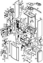
WD209/1/2000 Chapter 5 : Fault Finding The Keston Celsius 25 & 25P5.7 Exploded Assembly Diagrams5.7.1 Boiler Controls Assembly<strong>Installation</strong> & <strong>Servicing</strong> <strong>Instructions</strong> Page : 33
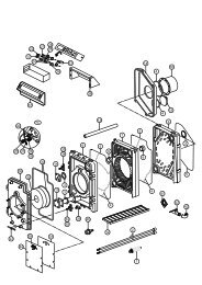
WD209/1/2000 Chapter 5 : Fault Finding The Keston Celsius 25 & 25P5.7.2 Waterway, Condensate & Flue Assembly<strong>Installation</strong> & <strong>Servicing</strong> <strong>Instructions</strong> Page : 36
WD209/1/2000 Chapter 5 : Fault Finding The Keston Celsius 25 & 25P5.7.3 Air - Gas Assembly<strong>Installation</strong> & <strong>Servicing</strong> <strong>Instructions</strong> Page : 35
WD209/1/2000 Chapter 5 : Fault Finding The Keston Celsius 25 & 25P5.7.4 Casing Assembly<strong>Installation</strong> & <strong>Servicing</strong> <strong>Instructions</strong> Page : 36
WD209/1/2000 Chapter 5 : Fault Finding The Keston Celsius 25 & 25P5.7.5 Exploded Diagrams Parts Reference ListBoiler Controls Assembly (Fig. 5.7.1)GC Number Code Description100 Ignition PCB (C.08.4.04.00.3)99 Control PCB (C.08.4.03.00.3)98 Fascia PCB (C.08.4.02.00.0)107 Electrical TerminalBlock(C.08.4.08.00.0)106 Cabinet Stat (C.08.4.21.00.0)Waterway, Condensate & Flue Assembly (Fig. 5.7.2)GC Number Code Description34 Heat Exchanger (C.08.2.18.00.0)32 Burner (C.08.2.32.00.0)43 Burner Head Gasket (C.08.2.00.07.0)42 Ignitor Gasket (C.08.2.00.06.0)31 Spark Ignition Electrode(C.08.2.01.00.2)57 Condensate Trap (C.08.2.14.00.0)47 Flow/Return Thermistor (C.08.2.08.00.0)46 Flue Overheat Stat (C.08.2.30.00.0)121 Flow Overheat Stat(C.08.2.07.00.0)48 Water Pressure Switch (C.08.2.23.00.0)52 Water Pump (C.08.2.11.00.0)Air - Gas Assembly (Fig. 5.7.3)GC Number Code Description78 Combustion Blower (C.08.3.01.00.1)80 Gas Valve (C.08.3.02.00.0)81 Mixing Venturi (C.08.3.03.00.0)Casing Assembly (Fig. 5.7.4)GC Number Code Description9 Cabinet (C.08.1.04.00.0)3 Data Badge (C.08.1.00.01.0) - NGData Badge (C.08.1.00.35.0) - LPG21 Ill. Wiring Diagram (C.08.1.00.13.0)19 Combustion Test Plug (C.08.1.00.07.0)<strong>Installation</strong> & <strong>Servicing</strong> <strong>Instructions</strong> Page : 37
WD209/1/2000 Chapter 6 : <strong>Servicing</strong> The Keston Celsius 25 & 25P6. ROUTINE (ANNUAL) SERVICINGTo ensure the continued safe and efficient operation of the boiler it is necessary to carry outroutine servicing at regular intervals. The frequency of the servicing will depend upon theparticular operating conditions, but it is recommended that an annual service should be carriedout by a qualified engineer.It is the law that any service work must be carried out by competent qualified persons.NB:When servicing ensure that the gas and electrical supplies to the boiler are isolatedbefore any work starts. It should be noted that turning the user control know fullyanticlockwise to “Standby” does not isolate the electrical supply and parts of the boiler willremain live.Hazardous materials are not used in the construction of the Celsius 25. However, duecare should be taken when handling boiler components.All joints should be checked for soundness after servicing and before firing the appliance.After servicing complete the relevant section of the Benchmark <strong>Installation</strong>, Commissioning andService Record Log Book. This should be in the possession of the User and should be left withthe User afterwards.6.1 Pre-Service ChecksIt is recommended that an inspection should be carried out prior to shutting down the unitfor servicing. Remove the front cover by removing the screws retaining the top andbottom. The following items should be observed:a. Smooth starting and running of the blower.b. Smooth lighting of the burner.c. Check for leakage of gas, gas/air or combustion products.d. Check for condensate leaks.e. Check that the pump error LED (red) does not indicate high or low flow rate atany time during operation.f. Check for water soundness.g. Inspect the flue vent and air intake pipework. Joints must be sound and allpipework well bracketed.h. Check that there is a steady fall back to the boiler from the flue pipe to allowcondensate to run back into the boiler.i. With the boiler operating at a low return temperature (i.e. less than 50 o C) checkthat the condensate flows freely from the condensate line.6.2 Recommended Routine Servicea. Remove the outer case by first removing the securing screws at the top andbottom of the appliance.b. Remove the burner head (Section 7.6) and inspect the burner appearance. Blackmarkings or other discoloration's on the gauze indicate too much gas or a lack ofair possibly due to a blocked air inlet. Any breakage's or damage to the burnermesh indicate the burner must be replaced.c. If necessary clean the burner with a mild household detergent and rinse under ahot running tap.d. If necessary, from visual inspection, clean the heat exchanger using a suitablestiff plastic bristle brush, vacuum out any large particles and flush the heatexchanger with fresh water until the water flowing from the condensate drain isclear.e. Remove the condensate trap (Section 7.8) and clean by flushing through withclean running water.f. Check the electrode assembly mounted on the heat exchanger. If the point isdamaged or burnt replace it.Check that the spark gap measures 3 mm.g. Replace the burner head, renewing the gasket if necessary, and reconnect thegas/air supply. Ensure the flanged gas/air supply joint is air tight.<strong>Installation</strong> & <strong>Servicing</strong> <strong>Instructions</strong> Page : 38
WD209/1/2000 Chapter 6 : <strong>Servicing</strong> The Keston Celsius 25 & 25Ph. Turn on the electrical supply to the boiler and allow the boiler to reach operatingtemperature levels.i. Recheck the burner pressure by following the procedure detailed in Section 4.7j. Remove the combustion test point plug from the flue pipe. This is situated on theflue spigot out of the cabinet.k. Using an approved combustion tester sample the flue products via thecombustion test point. CO 2 levels of between 8% and 9%, for natural gas andbetween 9.5% and 10.3% for LP gas, should be observed. If such levels are notobserved tune the combustion as described in Chapter 4 - Commissioning. Alsocheck the gas flow as detailed in Sections 4.8 and 4.9l. Replace the combustion test point plug.m. Check all joints for soundness up to the gas burner.n. Complete relevant box on back of Benchmark Log Book.<strong>Installation</strong> & <strong>Servicing</strong> <strong>Instructions</strong> Page : 39
WD209/1/2000 Chapter 7 : Replacement Of Parts The Keston Celsius 25 & 25P7. REPLACEMENT OF PARTSINDEX7.0 GENERAL7.1 PRECAUTIONS7.2 ACCESS7.3 PROCEDURES - GENERAL7.4 ELECTRICAL7.4.1 FASCIA PCB7.4.2 BOILER FLOW & RETURN THERMISTORS7.4.3 CABINET TEMPERATURE SENSOR7.4.4 FLOW OVERHEAT THERMOSTAT & FLUE PROTECTIONTHERMOMSTAT7.4.5 WATER PRESSURE SWITCH7.4.6 IGNITION PCB7.4.7 CONTROL PCB7.4.8 COMBUSTION BLOWER7.4.9 GAS CONTROL VALVE7.5 SPARK IGNITION/FLAME DETECTION ELECTRODE7.6 BURNER7.7 HEAT EXCHANGER7.8 CONDENSATE TRAP7.9 PUMP<strong>Installation</strong> & <strong>Servicing</strong> <strong>Instructions</strong> Page : 40
WD209/1/2000 Chapter 7 : Replacement Of Parts The Keston Celsius 25 & 25P7.0 GENERALThe following must always be carried out by a competent/qualified person.7.1 PRECAUTIONSi) Always switch off the mains electricity supply and disconnect the plug at theisolating switch and socket. (If a switch only is used then remove the fuse.)ii) Gain access to the appliance (Section 7.2) and turn off the gas supply at theappliance service cock.WARNING :Parts of the boiler internal wiring will remain live even after turningthe User Control Knob to the Standby position. Shut off the powersupply at the isolating switch before working on the appliance.7.2 ACCESSi) Remove the cabinet by removing the screws to the top and bottom of the cabinet.ii)Access to the control, ignition and fascia PCB’s of the control panel can begained by removing the controls cover at the bottom left hand corner of the boiler.Remove the two sliding covers to the sides of the housing then gently pull thecontrol panel forward of the PCB housing.7.3 REPLACEMENT PROCEDURESi) Always replace in the reverse order unless otherwise stated.ii) Electrical connections must be remade in accordance with the Wiring Diagram(Section 5.5).iii) Test the soundness of any gas carrying or water carrying joint broken during theservice procedures.7.4 ELECTRICAL COMPONENTS7.4.1 Fascia PCB (Fig. 5.7.1 item 98)i) Isolate the appliance (Section 7.1)i) Gain access (Section 7.2)iii) Remove the user control knob by fulling forward off the shaft.iv) Undo and remove the locknut securing the fascia PCB to the front plateof the controls housing.v) Disconnect the fascia PCB by unplugging the 13-way connection block.vi) Reassemble (Section 7.3)vii) Check for correct operation of the fascia PCB.7.4.2 Boiler Flow and Return Thermistors (Fig. 5.7.2 item 47)i) Isolate the appliance (Section 7.1)ii) Gain access (Section 7.2)iii) Remove the push on connectors from the thermistor taking note of thecorrect positions.iv) Unscrew the two retaining screws and remove the thermistor.v) Reassemble (Section 7.3)NB:When fitting the new thermistor it is an advantage to smear a thinfilm of heat sink compound between the thermistor and plate.This, combined with fitting the new thermistor tightly to the plate,ensures a good contact.7.4.3 Cabinet Temperature Sensor (Fig 5.7.1 item 106)i) Isolate the appliance (Section 7.1)ii) Gain access (Section 7.2)iii)Remove the cabinet temperature sensor from the connector block byslackening the retaining screws.iv) Reassemble (Section 7.3)7.4.4 Flow Overheat Thermostat (Fig. 5.7.2 item 121) & Flue ProtectionThermostat (Fig. 5.7.2 item 46)i) Isolate the appliance (Section 7.1)ii) Gain access (Section 7.2)<strong>Installation</strong> & <strong>Servicing</strong> <strong>Instructions</strong> Page : 41
WD209/1/2000 Chapter 7 : Replacement Of Parts The Keston Celsius 25 & 25Piii) Remove the push on connectors from the thermostat taking note of thecorrect positions.iv) Unscrew the two retaining screws, or nuts, and remove the thermostat.v) Reassemble (Section 7.3)NB: When fitting the new thermostat it is an advantage to smear athin film of heat sink compound between the thermostat andplate. This, combined with fitting the new thermostat tightly to theplate, ensures a good contact.7.4.5 Water Pressure Switch (Fig. 5.7.2 item 48)i) Isolate the appliance (Section 7.1)ii) Shut off the water supply to the appliance.iii) Gain access (Section 7.2)iv) Drain the system to below the level of the appliance using the drain offtap at the base of the flow pipe from the heat exchanger.v) Remove the push on connectors from the water pressure switch takingnote of the correct positions.vi) Unscrew the pressure switch.vii) Reassemble (Section 7.3).NB: Use a little jointing compound or PTFE tape on the thread.viii) Refill the system (See Section 4 - Commissioning).7.4.6 Ignition PCB (Fig. 5.7.1 item 100)i) Isolate the appliance (Section 7.1)ii) Gain access (Section 7.2)iii) Remove the fascia plate by removing the four retaining screws (Fig 5.7.1items 112) and pull forward leaving to one side.iv) Remove the left hand side panel to the control boards housing by slidingforward.v) Pull off the multi-pin connector and HT lead away from the board.vi) Slide the ignition PCB from the PCB housing.vii) Reassemble (Section 7.3)7.4.7 Control PCB (Fig. 5.7.1 item 99)i) Isolate the appliance (Section 7.1)ii) Gain access (Section 7.2)iii) Remove the fascia plate by removing the four retaining screws (Fig 5.7.1items 112) and pull forward leaving to one side.iv) Remove the right hand side panel to the control boards housing bysliding forward.iv) Pull off the multi-pin connectors away from the board.v) Slide the control PCB from the PCB housing.vi) Reassemble (Section 7.3)7.4.8 Combustion Blower (Fig. 5.7.3 item 78)i) Isolate the appliance (Section 7.1)ii) Gain access (Section 7.2)iii) Disconnect the connector block from the combustion blower.iv) Unscrew the bolts securing the venturi elbow (fig 5.7.3 item 82) to theinlet port of the combustion blower.v) Remove the four bolts securing the combustion blower outlet flange tothe burner and remove the combustion blower.vi) Reassemble (Section 7.3)NB:When reassembling inspect any gaskets for damage and replaceif necessary.7.4.9 Gas Control Valve (Fig. 5.7.3 item 80)i) Isolate the appliance (Section 7.1)ii) Gain access (Section 7.2)iii) Remove the push on connector block to the gas valve.iv) Remove the plastic air tube to the base of the gas valve.v) Undo the union fitting (Fig 5.7.3 item 89) securing the gas inlet pipe tothe gas control valve.<strong>Installation</strong> & <strong>Servicing</strong> <strong>Instructions</strong> Page : 42
WD209/1/2000 Chapter 7 : Replacement Of Parts The Keston Celsius 25 & 25Pvi)vii)viii)Undo the four bolts fixing the mixing venturi (fig 5.7.3 item 81) to theventuri elbow (fig 5.7.3 item 82).Remove the gas valve and mixing venturi as one.Separate the mixing venturi from the gas valve by unscrewing the BSPnipple between the two.ix) Reassemble (Section 7.3)x) Check the gas rate (See Section 4 - Commissioning)7.5 SPARK IGNITION/FLAME DETECTION ELECTRODE (Fig. 5.7.2 item 31)i) Isolate the appliance (Section 7.1)ii) Gain access (Section 7.2)iii) Remove the fascia plate by removing the four retaining screws (Fig 5.7.1 items112) and pull forward leaving to one side.iv) Remove the left hand side panel to the control boards housing by sliding forward.v) Remove the pull off HT lead to the ignition PCB (Fig 5.7.1 item 100).vi)vii)Remove the pull off HT lead to the spark ignition electrode.Undo the screws to the spark ignition electrode flange located on the heatexchanger side panel and withdraw the spark ignition electrode.viii) Reassemble (Section 7.3)NB:When reassembling inspect the gasket for damage and replace ifnecessary.With the new spark ignition electrode in place it is essential to ensure thegap between the tip of the electrode and the earth post is 3 mm.Distances above or below 3 mm will affect ignition performance. Ifnecessary gently bend the electrode taking care not to damage theceramic insulator.7.6 BURNER (Fig. 5.7.2 items 32)i) Isolate the appliance (Section 7.1)ii) Gain access (Section 7.2)iii) Remove the combustion blower (Section 7.4.9)iv) Remove the 10 nuts fixing the burner to the top of the heat exchanger.v) Withdraw the burner from the top of the heat exchanger.vi) Reassemble (Section 7.3)NB:When reassembling inspect any gaskets for damage and replace ifnecessary.7.7 HEAT EXCHANGER (Fig. 5.7.2 item 34)i) Isolate the appliance (Section 7.1)ii) Gain access (Section 7.2)iii) Shut of the water supply to the appliance.iv) Remove the burner (Section 7.6)v) Drain the system to below the level of the appliance using the drain off tap at thebase of the boiler flow pipe.vi) Remove the flue protection thermostat (Section 7.4.4)vii) Remove the spark ignition/flame detection electrode (Section 7.5)viii) Remove the flexible flue hose connection by slackening the retaining strap andpulling the hose of the heat exchanger spigot.ix) Remove the condensate trap hose (Fig 5.7.2 item 55) by releasing the retainingclamp and pulling the hose away from the spigot at the base of the heatexchanger flue outlet box.x) Disconnect the flow and return pipe unions (Fig 5.7.2 item 45) from the heatexchanger.xi) Remove the two allen bolts fixing the heat exchanger to the top mounting bracket(Fig 5.7.2 item 72)xii) Remove the heat exchangerxiii) Reassemble (Section 7.3)xiv) Recommission (Section 4 - Commissioning)<strong>Installation</strong> & <strong>Servicing</strong> <strong>Instructions</strong> Page : 43
WD209/1/2000 Chapter 7 : Replacement Of Parts The Keston Celsius 25 & 25P7.8 CONDENSATE TRAP (Fig. 5.7.2 item 57)i) Isolate the appliance (Section 7.1)ii) Gain access (Section 7.2)iii) Disconnect the condensate line from the base of the heat exchanger.iv) Disconnect the condense lines from the projection of the condensate trap fromthe base of the cabinet.v) Withdraw the condensate trap.vi) Mop up any spilled condensate.vii) Reassemble (Section 7.3)NB:When re-fitting the condensate trap pour water onto the condensate hosefrom the base of the heat exchanger until nearly full. Then reconnect thecondensate hose to the base of the heat exchanger.7.9 PUMP (Fig 5.7.2 item 52)i) Isolate the appliance (Section 7.1)ii) Gain Access (section 7.2)iii) Isolate the waterways to the pump using the pump isolation valves (Fig 5.7.2 item51)iv) Disconnect the pump electrical cable from the connections box of the pump headtaking note of the correct position.v) Remove the four allen bolts securing the pump head to the pump back plate.vi)vii)Remove the pump head.If using a standard Grundfos UPS15-60 pump head as replacementa) Remove the electrical cover to the new pump head.b) Remove the capacitor and link wire in the 8-way terminal block in thenew pump head and discard.viii) Reassemble (Section 7.3)<strong>Installation</strong> & <strong>Servicing</strong> <strong>Instructions</strong> Page : 44
WD209/1/2000 Chapter 8 : Spare Parts Listings The Keston Celsius 25 & 25P8. SHORT SPARE PARTS LISTItem GC No Part Denomination Item GC No Part Denomination32 Burner 43 Burner Gasket42 Ignitor Gasket 31 Ignitor/Sensor Probe47 Flow/Return 46 Flue ProtectionThermistorsThermostat121 Flow Overheat 80 Gas ValveThermostat<strong>Installation</strong> & <strong>Servicing</strong> <strong>Instructions</strong> Page : 45
WD209/1/2000 Chapter 8 : Spare Parts Listings The Keston Celsius 25 & 25PItem GC No Part Denomination Item GC No Part Denomination100 Ignition PCB 99 Control PCB98 Fascia PCB<strong>Installation</strong> & <strong>Servicing</strong> <strong>Instructions</strong> Page : 46
WD209/1/2000 Chapter 8 : Spare Parts Listings The Keston Celsius 25 & 25PSHORT SPARE PARTS LIST FOR THE KESTONCONDENSING BOILER RANGEItem GC No Part Denomination47 - Flow/Return Temperature Thermistor48 - Water Pressure Switch121 - Flow Overheat Thermostat46 - Flue Protection Thermostat99 - Control PCB100 - Ingition PCB98 - Fascia PCB103 - Transformer78 - Combustion Blower80 - Gas Valve57 - Condensate Trap31 - Ignition Electrode32 - Burner34 - Heat Exchanger52 - Circulating Pump<strong>Installation</strong> & <strong>Servicing</strong> <strong>Instructions</strong> Page : 45
KESTON CONDENSING BOILERSIMPORTANTCELSIUS 25 & 25PINSTALLATION KEY POINTS† Read <strong>Installation</strong> Manual Carefully† Ensure that there is at least 9 feet head of water pressure at thetop of the boiler and an open bypass across primary flow andreturn (for open vented systems).† Ensure that ALL dust particles, filings , plastic chips etc. areremoved from the inlet pipe.† If the installation is a replacement the system must be flushedclean. System should be drained hot, then refilled, then drainedagain until the water is clean.† Ensure that there is a proper electrical supply ie 230V fused at3A for the permanent live and that the factory link between SLand SL(link) has been removed..† Take great care with pipe connections to ensure that no damageis done to the internal pipework.† Ensure that the 22mm condensate pipe is not exposed tofreezing conditions.† Make sure that the exhaust pipe terminates away from windowsor vents and is out of reach.† Make sure that the air inlet and exhaust pipe outlets are at least200mm apart.† Check tightness of all connections in the boiler before firing.† Ensure that the terminals supplied are fitted to both the exhaustand air inlet pipes.† The system must be free from air before firing.† If TRV's are installed on radiators ensure that a bypass isinstalled to maintain required flow.† Complete the appropriate sections of the Benchmark<strong>Installation</strong>, Commissioning and Service Record Log Book.Hand over log book to customer.WD210/1/2000