Installation And Servicing Instructions - Heatingspares247.com
Installation And Servicing Instructions - Heatingspares247.com
Installation And Servicing Instructions - Heatingspares247.com
- No tags were found...

Create successful ePaper yourself
Turn your PDF publications into a flip-book with our unique Google optimized e-Paper software.
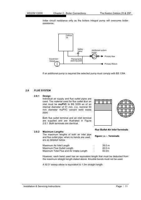
WD209/1/2000 Chapter 2 - Boiler Connections The Keston Celsius 25 & 25Pindex circuit resistance only as the boilers integral pump will overcome boilerresistance.Celsius25ExpansionVesselSafetyValvePermanentlyopen by-passAdditional systempump.Primary flowPrimary ReturnIf an additional pump is required the selected pump must comply with BS 1394.2.8 FLUE SYSTEM2.8.1 DesignIndividual air supply and flue outlet pipes areused. The material used for flue outlet &/or airinlet must be muPVC to BS 5255 an of aninternal diameter of 51 mm. (i.e. nominal 50mm diameter muPVC solvent weld wastepipe)Both flue outlet terminal and air inlet terminalare supplied and are illustrated in Figure2.8.1. Both terminals are identical.2.8.2 Maximum LengthsThe maximum lengths of both air inlet pipeand flue outlet pipe, when no bends are used,are as detailed below.Flue Outlet/Air Inlet TerminalsFigure 2.8.1 : TerminalsMaximum Air Inlet Length : 39.0 mMaximum Flue Outlet Length : 20.0 mMaximum Total Flue and Air Intake Length : 40.0mHowever, each bend used has an equivalent length that must be deducted fromthe maximum straight length stated above. Knuckle bends must not be used.A 92.5 o sweep elbow is equivalent to 1.0m straight length.<strong>Installation</strong> & <strong>Servicing</strong> <strong>Instructions</strong> Page : 11