Installation And Servicing Instructions - Heatingspares247.com
Installation And Servicing Instructions - Heatingspares247.com
Installation And Servicing Instructions - Heatingspares247.com
- No tags were found...

Create successful ePaper yourself
Turn your PDF publications into a flip-book with our unique Google optimized e-Paper software.
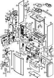
WD209/1/2000 Chapter 7 : Replacement Of Parts The Keston Celsius 25 & 25Piii) Remove the push on connectors from the thermostat taking note of thecorrect positions.iv) Unscrew the two retaining screws, or nuts, and remove the thermostat.v) Reassemble (Section 7.3)NB: When fitting the new thermostat it is an advantage to smear athin film of heat sink compound between the thermostat andplate. This, combined with fitting the new thermostat tightly to theplate, ensures a good contact.7.4.5 Water Pressure Switch (Fig. 5.7.2 item 48)i) Isolate the appliance (Section 7.1)ii) Shut off the water supply to the appliance.iii) Gain access (Section 7.2)iv) Drain the system to below the level of the appliance using the drain offtap at the base of the flow pipe from the heat exchanger.v) Remove the push on connectors from the water pressure switch takingnote of the correct positions.vi) Unscrew the pressure switch.vii) Reassemble (Section 7.3).NB: Use a little jointing compound or PTFE tape on the thread.viii) Refill the system (See Section 4 - Commissioning).7.4.6 Ignition PCB (Fig. 5.7.1 item 100)i) Isolate the appliance (Section 7.1)ii) Gain access (Section 7.2)iii) Remove the fascia plate by removing the four retaining screws (Fig 5.7.1items 112) and pull forward leaving to one side.iv) Remove the left hand side panel to the control boards housing by slidingforward.v) Pull off the multi-pin connector and HT lead away from the board.vi) Slide the ignition PCB from the PCB housing.vii) Reassemble (Section 7.3)7.4.7 Control PCB (Fig. 5.7.1 item 99)i) Isolate the appliance (Section 7.1)ii) Gain access (Section 7.2)iii) Remove the fascia plate by removing the four retaining screws (Fig 5.7.1items 112) and pull forward leaving to one side.iv) Remove the right hand side panel to the control boards housing bysliding forward.iv) Pull off the multi-pin connectors away from the board.v) Slide the control PCB from the PCB housing.vi) Reassemble (Section 7.3)7.4.8 Combustion Blower (Fig. 5.7.3 item 78)i) Isolate the appliance (Section 7.1)ii) Gain access (Section 7.2)iii) Disconnect the connector block from the combustion blower.iv) Unscrew the bolts securing the venturi elbow (fig 5.7.3 item 82) to theinlet port of the combustion blower.v) Remove the four bolts securing the combustion blower outlet flange tothe burner and remove the combustion blower.vi) Reassemble (Section 7.3)NB:When reassembling inspect any gaskets for damage and replaceif necessary.7.4.9 Gas Control Valve (Fig. 5.7.3 item 80)i) Isolate the appliance (Section 7.1)ii) Gain access (Section 7.2)iii) Remove the push on connector block to the gas valve.iv) Remove the plastic air tube to the base of the gas valve.v) Undo the union fitting (Fig 5.7.3 item 89) securing the gas inlet pipe tothe gas control valve.<strong>Installation</strong> & <strong>Servicing</strong> <strong>Instructions</strong> Page : 42