Installation And Servicing Instructions - Heatingspares247.com
Installation And Servicing Instructions - Heatingspares247.com
Installation And Servicing Instructions - Heatingspares247.com
- No tags were found...

Create successful ePaper yourself
Turn your PDF publications into a flip-book with our unique Google optimized e-Paper software.
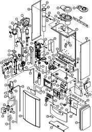
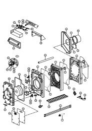
WD209/1/2000 Chapter 3 : <strong>Installation</strong> The Keston Celsius 25 & 25PN - Blue wire (Neutral) for 3A permanent and 2A switchedsuppliesPL - Brown wire (Live) 3A permanent supply- Yellow/Green Wire (Earth)SL - Brown wire (Live) 2A switched supply.ORSL & SL(LINK) -Link connection via volt free external controlsLO - To external 230V remote lockout monitoring (optional)RUN - To external 230V remote run monitoring (optional)Ensure connection is made such that if the cable slips in its anchorage thecurrent carrying conductors become taut before the earthing conductor.3.9 EXCHANGING A BOILERBefore removing an existing boiler add Fernox Supafloc , or equivalent cleaning agent, inaccordance with the manufacturers instructions. Open all radiator valves and fire theboiler. When the system is fully heated, shut off the gas supply and drain down thecentral heating system.ImportantThe Celsius 25 condensing boiler contains components which could be damaged orblocked by grease, dirt or solder etc. It is essential that sludge or scale is removed froman existing system.The guarantee provided with the Keston Celsius 25 does not cover damage caused bysystem debris or sludge.Connect the new boiler as instructed in this manual and fit in accordance with Sections3.1 to 3.8For sealed systems, fill to a pressure of about 2.7 bar. Check the complete system forwater soundness. If leaks need to be rectified using flux or solder the system must beflushed cold again before proceeding.Reduce the pressure to the Initial System Design Pressure for sealed systems, ifapplicable. Vent the system.Gas SupplyThe complete gas installation up to the boiler service cock must be checked forsoundness. BS 6891.Electrical <strong>Installation</strong>Carry out preliminary electrical safety checks, i.e. Earth continuity, Polarity, Resistance toEarth, Short Circuit using a suitable test meter.Initial FiringThe gas pressure setting is factory adjusted to within the required range and doesnot need re-adjustment. If the reading is incorrect then check such factors assoundness of the air and flue pipe joints, pressure sensible joints and the gas inletpressure (minimum 18 mbar required for Natural Gas and 31 mbar required for LP gas). Ifall joints are sound and the gas inlet pressure is satisfactory set the gas pressure andcheck the gas input. Full details of this procedure are given in Section 4.8 Timing TheGas Meter.Combustion TestingIt is advisable on all installations that the combustion quality is checked by measuring thecarbon dioxide (CO 2), or oxygen (O 2) level. This procedure is detailed in Section 4.9Combustion Testing. Badly tuned combustion will lead to reduce the life of the boiler andinvalidate the warranty.<strong>Installation</strong> & <strong>Servicing</strong> <strong>Instructions</strong> Page : 18