Installation & Service Instructions Kingfisher Mf 40 – 100 - AC Wilgar
Installation & Service Instructions Kingfisher Mf 40 – 100 - AC Wilgar
Installation & Service Instructions Kingfisher Mf 40 – 100 - AC Wilgar

Create successful ePaper yourself
Turn your PDF publications into a flip-book with our unique Google optimized e-Paper software.
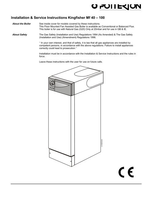
The Gas Safety (<strong>Installation</strong> and Use) Regulations 1994(As Amended) & The Gas Safety (<strong>Installation</strong> and Use)This appliance must be installed and serviced by acompetent person, in accordance with the aboveregulations.In the UK 'Corgi' Registered Installers (including the regionsof British Gas Plc) undertake to work to a safe andsatisfactory standard.Failure to install appliances correctly could lead toprosecution.It is in your own interest, and that of safety, to ensure thatthe regulations are complied with.<strong>Kingfisher</strong> <strong>Mf</strong> boilers are fully automatically controlled, floorstanding, fan powered, balanced or conventional fluedappliances using a cast iron heat exchanger and areavailable in outputs ranging from 8.8 - 29.31 kW (<strong>40</strong>,000 -<strong>100</strong>,000 Btu/h)The boilers are designed for use on fully pumped openvented or sealed water systems with an indirect hot watercylinder or open vented gravity systems. THEY MUST NOTBE CONNECTED TO A DIRECT CYLINDER.The boilers are for use on Natural Gas (G20) only.Samples of the Potterton <strong>Kingfisher</strong> MF gas boilers havebeen examined by British Gas Plc, a United KingdomNotified Body. The range is certified to comply with theessential requirements of the Gas Appliance Directive90/396/EEC, the Low Voltage Directive 72/23/EEC andshows compliance with the Electro Magnetic CompatibilityDirective 89/336/EEC and are therefore permitted to carrythe CE Mark.Delivery & Kits AvailableRS Model is delivered in two packages (1) the boiler withfittings and (2) the flue assembly.CF Model is delivered in one package.Health and Safety Information for theInstaller and <strong>Service</strong> EngineerUnder the Consumer Protection Act 1987 and Section 6 ofthe Health and Safety at Work Act 1974, we are required toprovide information on substances hazardous to health.Small quantities of adhesives and sealants used in theproduct are cured and present no known hazards.The following substances are also present.Insulation and SealsMaterial - Man Made Mineral Fibre.Description - Boards, Ropes, Gaskets.Known Hazards - Some people can suffer reddeningand itching of the skin. Fibre entry into the eye willcause foreign body irritation which can cause severeirritation to people wearing contact lenses. Irritation torespiratory tract.Precautions - Dust goggles will protect eyes. Peoplewith a history of skin complaints may be particularlysusceptible to irritation. High dust levels are only likelyto arise following harsh abrasion.In general, normalhandling and use will not present high risk, follow goodhygiene practices, wash hands before, touching eyes,consuming food, drinking or using the toilet.First Aid - Medical attention must be sought followingeye contact or prolonged reddening of the skin.Codes of PracticeThe boiler must be installed in accordance with: The GasSafety (<strong>Installation</strong> and Use) Regulations 1994 (AsAmended) & The Gas Safety (<strong>Installation</strong> and Use)(Amendment) Regulations 1996. and the current issue of:-The Building Regulations, Building Standards (Scotland)Regulations, Local Building Regulations, Model and localWater Undertaking Bye-laws, IEE Wiring Regulations andHealth & Safety Document No. 635 "The Electricity at WorkRegulations 1989".IMPORTANTThis appliance has been certified for safety. It is therefore important that no external control device (e.g. fluedampers, economisers, etc.) be directly connected to the appliance unless covered by these <strong>Installation</strong> & <strong>Service</strong><strong>Instructions</strong> or otherwise recommended in writing. Any direct connection of a control device not approved byPotterton Myson Ltd, could invalidate the CE Certification and normal appliance warranty.Introduction 5
<strong>Installation</strong> Requirements - Page 61.1 Gas SupplyThe meter and supply pipes must be capable of deliveringthis quantity of gas in addition to the demand from anyother appliances in the house and must be governed at themeter.On 90 & <strong>100</strong> models, due to the gas flow rate required,22mm gas supply pipe should be used up to the inletconnection of the gas cock on the boiler.The complete installation must be tested for gas soundnessand purged as described in BS6891.1.2 Electricity Supply230V ~ 50Hz via a fused double pole switch with a contactseparation of at least 3 mm in both poles adjacent to theboiler. Power consumption is approximately 80W. Theremust be only one common isolator for the boiler and itscontrol system and it must provide complete electricalisolation. A plug (if fitted) must be accessible to the userafter installation of the appliance.Fuse the supply at 3 A. The minimum requirement for thepower supply cable is that it should be a PVC sheathedcord at least 0.75 mm² (24 x 0.2 mm) (code designationHO5 VV-F or HO5 VVH2-F) as specified in table 16 ofBS6500:1984.All wiring external to the boiler shall comply with the latestIEE Wiring Regulations, and any local regulations whichapply.WARNING: THIS APPLIANCE MUST BE EARTHED.In the event of an electrical fault after installation of theboiler, preliminary electrical systems checks must becarried out i.e. Earth Continuity, Short Circuit, Polarity andResistance to Earth.1.3 Location of BoilerThe boiler is not suitable for external installation. The boilermust stand firm and level. No special floor protection isneeded, but finishes which soften when warm e.g. linoleumand plastic floor tiles should be removed or may beprotected by an insulating sheet at least 10mm thick.The boiler must be installed so that the flue terminal isexposed to the external air. It is important that the positionof the terminal allows the free passage of air across it at alltimes.The boiler is suitable for installation against a combustiblewall e.g. wood cladding, provided that the flue duct is notcloser than 25 mm to combustible material. A metal sleeveshould be installed to surround the flue duct to provide a25mm annular space. Further guidance is given inBS54<strong>40</strong>:1:1990, sub-clauses 3.3 and 4.2.5.If the boiler is to be installed in a timber framed building itshould be fitted in accordance with the British Gaspublication- Part 19 - Building and Kitchen Work. If in doubtadvice must be sought from Potterton Myson.The boiler may be installed in any room, although particularattention is drawn to the requirements of the current IEEWiring Regulations and, in Scotland, the electricalprovisions of the Building Standards applicable in Scotlandwith respect to the installation of the boiler in a roomcontaining a bath or shower.RS Models: Where a room-sealed appliance is installed ina room containing a bath or shower, any electrical switchor appliance control, utilising mains electricity should be sosituated that it cannot be touched by a person using thebath or shower.CF Models: Conventional flue boilers can be installedeither in a kitchen or utility room or inside a suitablyventilated, purpose designed or modified compartment.Where the installation of the boiler will be in an unusualposition, special procedures may be necessary andBS6798 and BS5546 give detailed guidance on thisaspect.A compartment used to enclose the boiler must bedesigned and constructed specifically for this purpose. Anexisting compartment may be used provided that it ismodified for the purpose. Details of essential features ofcompartment design including airing cupboard installationsare given in BS6798 and BS5546 and should be compliedwith.RS Models: If the boiler is fitted under a worksurface it maybe located next to or between kitchen cabinets or fittingsproviding that the front of the boiler case is visible andunobstructed, the special requirements for an enclosedcompartment will not applyIf the boiler is to be fitted under a worksurface, theworksurface may need to be removed to install the boiler. Itis advisable that the worksurface be removable to allowaccess for servicing if required.If the boiler is to be fitted in a run of kitchen units it isrecommended that the boiler is fitted first or the adjacentunits removed.The boiler requires the clearances shown in Fig. 2.Conventional Flue Models - See Page 7 & 8.Balanced Flue Models - See Pages 9 & 10.6 <strong>Installation</strong> Requirements Publication No. 560<strong>100</strong>
<strong>Installation</strong> Requirements - Page 7Conventional Flue Models1.4 Air SupplyThe air requirements must meet BS 54<strong>40</strong> Part 2.The room in which the boiler is installed must beventilated. Ventilation of the room containing the boilershall include air for combustion and correct operation ofthe flue (ie Draught Diverter dilution).A permanent air vent shall be provided in an outside wallof the building either at high or low level in accordancewith Table 1.Open FlueBoiler In RoomTable 1The opening may be:Combustion Aira) Directly into the room or space containing the boiler or Free Area cm sq.indirectly via an opening of at least the same area.CF<strong>40</strong> 35b) Via a duct either directly into the room or space or CF50 51indirectly via an opening of at least the same free area. CF60 68CF70 84Where air is drawn indirectly from outside through more CF80 101than two air vents refer to BS 54<strong>40</strong> Part 2. CF90 117CF<strong>100</strong> 134Where an extraction fan is fitted in the room containing theboiler, special ventilation requirements must be implemented.Refer to BS 54<strong>40</strong> Part 2.Any grille and/or duct should be so sited and of a type notto become easily blocked or flooded and should offer lowresistance to airflow.If the boiler is installed in a compartment, permanent airvents are required in the compartment, one at high leveland one at low level (Table 2), either direct to the outsideair or to a room.Both high level and low level air vents must communicatewith the same room or must be on the same wall tooutside air.If the boiler is installed in a compartment with a door, allowat least 25 mm clearance between the front of the boilerand door for air movement.Table 2Open Flue Boiler CompartmentVentilated From InsideCON0010BCompartment VentilationFree Area cm sq. High Level Low LevelCF<strong>40</strong> 132 264CF50 165 330CF60 198 396CF70 231 462CF80 264 528CF90 297 594CF<strong>100</strong> 331 662Publication No. 560<strong>100</strong> <strong>Installation</strong> Requirements 7
<strong>Installation</strong> Requirements - Page 81.5 Flue SystemsA flue system (lined throughout its length) must beprovided to evacuate the flue products of combustion fromthe boiler. Reference should be made to the buildingregulations and BS 54<strong>40</strong>:1. and the flue system efficiencyshould be checked in accordance with BS 54<strong>40</strong>.Ideally a flue should rise vertically and any terminal ortermination point shall be positioned so that combustionproducts can disperse safely at all times. Therefore forpractical purposes, the flue should have the shortestpossible run to external atmosphere, with as near verticalrise as possible, 90° bends should be avoided. Theterminal must be at least above roof level and of a typeapproved by British Gas.There should be at least 600mm of vertical flue from theboiler flue socket.Horizontal runs should be avoided, however if a nearhorizontal flue run is unavoidable, the total vertical heightnecessary should be calculated in accordance with BS54<strong>40</strong>:1.If an existing chimney is used, ensure that it is thoroughlyswept before lining or connecting the boiler. The liner musthave an internal diameter of <strong>100</strong>mm for the <strong>40</strong> to 60models and 125mm for the 70 to <strong>100</strong> models.Care should be taken to avoid condensation in the flue.In the case of a pre-lined chimney, it must be connected tothe socket of the boiler flue hood with a length of purposemade flue.Where flue size is to be determined by calculation, thefollowing information should be usedModel Mass Rate of Combustion AverageSize Products (g/sec) Temp. (ºC)<strong>40</strong> 20.91 7150 23.92 8360 27.11 9170 32.46 9280 36.19 9490 37.97 98<strong>100</strong> 41.43 103Next Section is 1.6 The System.8 <strong>Installation</strong> Requirements Publication No. 560<strong>100</strong>
<strong>Installation</strong> Requirements - Page 9Balanced Flue Models1.4 Air SupplyThe air requirements must meet BS 54<strong>40</strong> Part 2.Boiler In RoomThe room in which the boiler is installed does not require apurpose provided air vent.If the boiler is installed in a compartment, permanent airvents are required in the compartment, one at high leveland one at low level, either direct to the outside air or to aroom. Both high level and low level air vents mustcommunicate with the same room or must be on the samewall to outside air. Both the high level and low level ventmust each have a combined free area in accordance withTable 3.If the boiler is installed in a compartment with a door, allowat least 25mm clearance between the front of the boiler andthe door for air movement.Balanced Flue No CombustionAir Inlet Required To RoomBoiler In Compartment1.5 Flue Systems & Terminal LocationHorizontal - Concentric (Left, Right or Rear).The flue/terminal assembly supplied is suitable for awall thickness of between 150mm and <strong>40</strong>0mm.A flue/terminal assembly suitable for a wall thickness ofup to 600mm is also available.Balanced Flue CompartmentVentilated From InsideCON00012ATable 3Both the flue/terminal assemblies are telescopic and Compartment Ventilationthe minimum lengths (150 mm/6 in) are achievedby cutting. Free Area cm sq. High Level Low LevelA 1m flue extension is available. Under no RS<strong>40</strong> 132 132circumstances should the total flue length exceed:- RS50 165 165RS60 198 1983.4m <strong>40</strong> to 70 models RS70 231 2312.4m 80 model RS80 264 2641.4m 90 model RS90 297 2971.0m <strong>100</strong> model RS<strong>100</strong> 331 331Vertical - Concentric.3.4m <strong>40</strong> - 70 models OnlyNote: If ventilating directly to outside, the figures shown inTable 3 can be halved.Where bends may be being used, the total flue length willbe reduced, see Page 17 Item 11 for more details.See separate <strong>Installation</strong> <strong>Instructions</strong> supplied with the flue.Publication No. 560<strong>100</strong> <strong>Installation</strong> Requirements 9
<strong>Installation</strong> Requirements - Page 10Where a horizontal flue is sited less than 2m above abalcony, above ground, or above a flat roof to which peoplehave access, a suitable terminal guard must be fitted. Thisserves two purposes, to protect the terminal againstdamage or interference and to protect passers-by. Aterminal guard is available (Sales Code:PTERMGUARDEF), this should be fitted centrally aboutthe terminal.Note: Where a flue terminal is installed less than 1 metrefrom a plastic, or painted gutter, or 500mm from paintedeaves, an aluminium shield 1 metre long, should be fittedto the underside of the gutter or painted surface. Asuitable wall plate should be fitted to the painted wallsurface of a mobile home.IMPORTANT: It is absolutely ESSENTIAL, to ensure thatproducts of combustion discharging from the terminalcannot re-enter the building, or any other adjacent building,through ventilators, windows, doors, natural air infiltration,or forced ventilation/air conditioning. If products ofcombustion are found to be re-entering any building, theappliance MUST be turned OFF IMMEDIATELY.AHorizontal FluesCPOSITIONHORIZONTAL FLUESMIN. DISTANCE mmTO EDGE OF TERMINALFGAFlueTerminalsEGB,C B,CKF FGJH,IBelow CarportKL LKF FGDFKGA DIRECTLY BELOW AN OPENABLEWINDOW, AIR VENT, OR ANY OTHERVENTILATION OPENING 300B BELOW GUTTER, DRAIN/SOIL PIPE 75C BELOW EAVES 200D BELOW A BALCONY/CARPORT ROOF 200E FROM VERTICAL DRAIN PIPES ANDSOIL PIPES 25F FROM INTERNAL OR EXTERNAL CORNERS 25G ABOVE ADJ<strong>AC</strong>ENT GROUND OR BALCONYLEVEL 300H FROM A SURF<strong>AC</strong>E F<strong>AC</strong>ING THE TERMINAL 600I F<strong>AC</strong>ING TERMINALS 1,200J FROM OPENING (DOOR/WINDOW) INCARPORT INTO DWELLING 1,200K VERTICALLY FROM A TERMINAL ON THESAME WALL 1,500L HORIZONTALLY FROM A TERMINAL ONTHE SAME WALL 300VERTICAL FLUESNAPNRSQ QVertical FluesNCON0013AN ABOVE ROOF LEVEL (TO BASE OF TERMINAL) 300P FROM ADJ<strong>AC</strong>ENT WALL TO FLUE 210Q FROM INTERNAL CORNER TO FLUE 230R BELOW EAVES OR BALCONY 600S FROM F<strong>AC</strong>ING TERMINAL 1,20010 <strong>Installation</strong> Requirements Publication No. 560<strong>100</strong>
<strong>Installation</strong> Requirements - Page 111.6 The SystemThe boiler must be used on INDIRECT hot water systems only.It is suitable for use on open vented gravity domestic hotwater/pumped central heating systems or, fully pumpedsystems which may be sealed or open vented.Existing systems should be thoroughly cleansed prior to boilerinstallation.The system should be designed so that the maximum statichead does not exceed 30.5m and a minimum on fully pumpedsystems of 300mm. See Fig. 8.Gravity domestic hot water circuits should have a minimumcirculating head of 1.2m. See Fig. 7. Horizontal pipe runsshould be kept to a minimum.To prevent reverse circulation in the gravity circuit when thepump is running an injector tee is incorporated.The pump should preferably be fitted in the flow, thoughinstallation in the return is acceptable providing care is taken toensure air is not drawn into the system due to the negativepressure effects of the pump. Isolating valves must be fitted asclose as possible to allow replacement without systemdraining.Drain off taps should be fitted in the pipework close to theboiler and in the low points of the system. A drain point is alsoprovided on the heat exchanger should the boiler needdraining - see Fig. 17.Combined Gravity Hot Water PumpedCentral Heating Systems.Where a cylinder thermostat and zone valve are used tocontrol the temperature of the hot water it is recommendedthat a by-pass be installed in the gravity circuit. A suggestedmethod of doing this is shown in Fig. 7. where the bathroomradiator is connected into the gravity circuit and is fitted withtwo lockshield valves. Mechanically operated thermostaticdomestic hot water temperature control valves which allow theboiler to operate when the valve is closed or partially closedMUST NOT BE FITTED unless a bypass radiator is fitted.Note: The boiler has one flow and two return connections. Oncombined gravity DHW/Pumped central heating a Tee will beneeded in the flow which must be fitted directly to theconnecting pipe provided.Fully Pumped SystemsThe pump must be wired directly to the terminal block(See Fig. 15) as it will allow the pump to be controlled by theover-run device. This will ensure that the pump will continue torun after boiler shut down thus preventing nuisance operationof the overheat thermostat.If a three port diverter valve is used as shown in Figs.8 & 9, aby-pass is not necessary since one circuit is always open.Where a pair of two port valves are used, a by-pass isnecessary. It should be fitted with a lockshield valve and beadjusted to maintain a minimum flow through the boiler of 4.5litres/min (1 gal/min) see Figs. 8 & 9.Systems fitted with controls which allow the boiler to operatewhen both the hot water and central heating circuits areclosed i.e. mechanically operated thermostatic control valves,must be fitted with a by-pass circuit capable of:-1. Dissipating a minimum of 1kW (3,<strong>40</strong>0 Btu/h)2. Maintaining a minimum water flow through the boilerof 9 litres/min (2 gal/min).A suggested method of meeting these requirements by usinga bathroom radiator fitted with two lockshield valves is shownin Figs. 8 & 9.Diagrammatic layouts of a fully pumped system and acombined pumped central heating/gravity hot water systemare shown in Figs. 7 & 8.Sealed Systems (Fully Pumped)<strong>Installation</strong>The installation must comply with the requirements of BS6798: 1987 and BS 5449: Pt 1. The British Gas publication"British Gas Specification for Domestic Wet Central HeatingSystems" should also be consulted.Safety ValveA non-adjustable spring-loaded safety valve, preset to operateat 3 bar (45lbf/in²) shall be used. It must comply with BS 6759:Pt 1. and include a manual testing device. It shall bepositioned in the flow pipe either horizontally or verticallyupwards and close to the boiler. No shut-off valves are to beplaced between the boiler and the safety valve. The valveshould be installed into a discharge pipe which permits thesafe discharge of steam and hot water such that no hazard topersons or damage to electrical components is caused.Pressure GaugeA pressure gauge incorporating a fill pressure indicator,covering the range 0 - 4 bar (60 lbf/in²) shall be fitted to thesystem. It should be connected to the system, preferably atthe same point as the expansion vessel. Its location should bevisible from the filling point.Expansion VesselA diaphragm type expansion vessel to BS 4814: Pt 1. shall befitted close to the inlet side of the pump. The connectingpipework should not be less than 15mm. Pipework connectingthe expansion vessel should not incorporate valves of anysort. Methods of supporting the vessel are supplied by thevessel manufacturer. The nitrogen or air charge pressure ofthe expansion vessel shall not be less than the hydrostatichead, (height of the top point of the system above theexpansion vessel).Publication No. 560<strong>100</strong> <strong>Installation</strong> Requirements 11
<strong>Installation</strong> Requirements - Page 12To size the expansion vessel it is first necessary tocalculate the volume of water in the system in litres. Thefollowing volumes may be used as a conservative guide tocalculating the system volume.Boiler Heat Exchanger:Small Bore Pipework:Micro Bore Pipework:Steel Panel Radiators:systemLow Water Capacity Radiators:systemHot Water Cylinder:6.5 litres1 litre per kW of systemoutput7 litres8 litres per kW ofoutput2 litres per kW ofoutput2 litresIf the system is extended, the expansion vessel volumemay have to be increased unless provision has beenmade for extension. Where a vessel of the calculated sizeis not available, the next available larger size should beused. The boiler flow temperature is controlled atapproximately 82°C.CylinderThe hot water cylinder must be an indirect coil type or adirect cylinder fitted with an immersion calorifier suitable foroperating at a gauge pressure of 0.3 bar (5 lbf/in²) inexcess of safety valve setting. Single feed indirectcylinders are not suitable for sealed systems.Method of Make-upProvision shall be made for replacing water loss from thesystem either:-i) from a make-up vessel or tank mounted in aposition higher than the top point of the system,and connected through a non-return valve to thesystem on the return side of the hot water cylinderor the return side of all heat emitters.orii) where access to a make-up vessel would bedifficult by using the mains top up method or aremote automatic pressurisation and make-up unitas shown in Fig. 10.The vessel size can now be determined from theMains Connectioninformation in Table 4 where V = System volume in There shall be no connection to the mains water supplylitres.or to the water storage tank which supplies domesticVessel Charge Pressure (bar) 0.5 1.0 hot water even through a non-return valve, without theInitial System Pressure (bar) 1.0 1.0 approval of the Local Water Authority.Expansion Vessel Volume (litres) V x 0.11 V x 0.087Table 4.Filling PointThe system shall be fitted with a filling point at low levelwhich incorporates a stop valve to BS 1010 and a doublecheck valve (approved by the National Water Council) tobe fitted in this order from the system mains, see Fig. 10.Circulation Pump SelectionThe resistance through the heat exchangerwhen operating with a water flow rateproducing an 11°C temperature rise atmaximum boiler output are shown in Table5. If other controls such as 3 positionvalves are used in the system, theresistance through them, quoted in theirmanufacturers literature must be taken intoaccount. The pump may be fitted on eitherflow or return. It must be fitted with twoisolating valves which are positioned asclose to the pump as possible. Closing ofany valve must always leave the open ventunobstructed. On fully pumped systemseither return connection may be used.Pressure Drop(M)(2.5)(2.0)(1.5)(1.0)Hydraulic Resistance Through KIngfisher <strong>Mf</strong> Rangembar250200150<strong>100</strong>Table 5Appliance OutputBTU<strong>40</strong>5060708090<strong>100</strong>Appliance ResistanceWater Flow RateL/Min.15.219.12326.830.534.438.2Gravity Returnmbar m2032486380<strong>100</strong>1280.20.330.490.6<strong>40</strong>.821.021.3Pumped Returnmbar m305073981321622150.310.510.741.001.351.652.19Through PumpedReturn Connection(0.5)0500Through GravityReturn Connection0 5 10 15 20 25 30 35 <strong>40</strong>Flow Rate (L/Min.)CON0039C12 <strong>Installation</strong> Requirements Publication No. 560<strong>100</strong>
<strong>Installation</strong> Requirements - Page 13Fig. 7 & 8Publication No. 560<strong>100</strong> <strong>Installation</strong> Requirements 13
<strong>Installation</strong> Requirements - Page 14Fully PumpedSealed SystemMake UpVesselPressureGaugeOptional3 PortValveVentSafetyValveExpansionVesselAlternative By-passarrangement UsingThe BathroomRadiator Fitted WithTwo Lockshield ValvesOptionalZoneValvesFlowFillingPointBy-passBalancingValveReturnFig. 9Filling A Sealed Water System(Method 1)Filling A Sealed Water System(Method 2)Mains Topping-Up MethodNote: This Method Of Filling ASealed System May Only BeUsed If Acceptable To localWater UndertakingMains WaterSupply(<strong>Service</strong> Pipe)HoseUnionTemporaryHoseStopValveDoubleCheckValveCistern Filling MethodNote: Cistern To Be SuppliedThrough A Tempory ConnectionFrom A <strong>Service</strong> Pipe OrCold Water Distributing PipeCisternOverflowMainsWaterSupplyPressure PumpReducing Valve(If Required)StopValveCON0015AHeatingSystemHeatingSystemFig. 1014 <strong>Installation</strong> Requirements Publication No. 560<strong>100</strong>
2. <strong>Installation</strong> - Page 152.1 Install the boilerThese instructions assume you have decided on where theboiler will be located and the type of flue system to beused.1. Carefully unpack the boiler. Remove and place asidethe tailpipe/gravity stat kit and on CF boilers, theancillary bag containing the top and rear blankingplates with seal.2. Do not discard any packaging until all the items areaccounted for.3. Temporarily position the boiler to ensure whererequired, the top cover touches the wall. This sets theminimum rear clearance for the pipework. Mark theposition on the floor.4. Remove the plinth - 2 screws.5. Remove the front door - 2 screws, unhook and lift off.6. Remove the controls panel - open flap, 1 screwunhook and lift away.7. Remove the top cover - 2 screws, pull forward and liftoff.2.2 Install the flueInstall the flue type as required.Conventional Flue:1. Loosen the 4 screws securing the down draughtdiverter to the boiler, line the diverter up with the flueand fully tighten the screws.Note: From its fully rearward position the diverter willmove forward 50mm.Publication No. 560<strong>100</strong> <strong>Installation</strong> 15
<strong>Installation</strong> - Page 162. Attach the flue to the draught diverter.Attach the seal as shown and re-fit the topblanking plate.If the diverter is in the fully forward positionfit the rear blanking plate supplied.This product is fitted with a productsdischarge safety device (TTB) which mustnot be taken out of operation at any time.The component is fitted to ensure that anyblockage or partial blockage of the fluedoes not result in combustion productsdischarging into the room.Balanced Flue:1. Mark the flue outlet hole position on thewall as illustrated.Note: Ensure that the correct allowance ismade for side outlet when the boiler is notbeing pushed fully back.2. Carefully cut hole through wall.Maximum flue lengths are as follows:<strong>40</strong> - 70 models - 3.4m80 model - 2.4m90 model - 1.4m<strong>100</strong> model - 1.0mThese are for rear or side flue applicationssee Page 17 Fig. 13.3. Determine dimension X +20mm SeeFig.13.4. Extend telescopic flue to the requiredlength, minimum 20mm overlap.5. Drill through the pilot hole and secure witha self tapping screw.6. Wrap tape around the joint on the outerduct to seal the flue, slide drip ring intoposition to coincide with the air gap in thewall cavity.7. Slide the flue through the hole until it stopson the pin.16 <strong>Installation</strong> Publication No. 560<strong>100</strong>
<strong>Installation</strong> - Page 178. The boiler is supplied with the flueelbow set for the rear. For sideoutlet slacken the screws, turn theelbow as required and retightenscrews.Note: Ensure that the seals arestill correctly located.9. Slide the flue back until it engagesin the elbow bayonet connection,twist clockwise to lock.10. Drill through pilot hole and lockflue in position using the selftapping screw provided.11. Make good the wall around theflue, both inside and outside.For optional extras refer toPage 38 & 39. If a HorizontalExtension is required this MUSTbe combined with a Standard Flueas shown in the Maximum FlueLength Guide.If an in-line bend is required in theflue the following rules apply:-A 90° in-line bend is equivalent toa 1m length of flue.A 135° in-line bend is equivalent toa ½m length of flue.The maximum equivalent flueresistance allowed when usingbends is:-<strong>40</strong> - 70 models = 3.4m.80 model = 2.4m.90 - <strong>100</strong> models - No bendsallowed.Note: For flue lengths less thanthe minimum telescopic length, thetubes can be cut to suit. Ensurethat the same length is removedfrom the inner and outer tubes tomaintain a minimum 20mmoverlap.Fig. 13For further information seePublication No. 560096 -'Combination Flues'.Publication No. 560<strong>100</strong> <strong>Installation</strong> 17
<strong>Installation</strong> - Page 182.3 Connect the Gas Supply1. Ensure that the gas supply is isolated.2. Disconnect the gas cock from the gasvalve.3. Connect the gas supply to the gas cockusing a suitable adaptor.Important:Do not solder the fitting whilstassembled to the gas cock.The pipe diameter required will dependon the boiler model and the pipe lengthfrom the gas meter. Ensure that the gassupply pipe is selected in accordancewith BS 6891 so that an adequate gassupply to the boiler is provided.4. Connect the gas cock to the gas valve.Do not turn the gas supply on at thisstage.2.4 Connect the Water SystemWhen attaching the standard pipe connecting kit to the boiler please note that the seal is made by use of an 'O' ring, thereforesome pipe movement will be evident even though a water tight seal has been achieved. Excessive force is not necessary andcould result in damage to the appliance.1. Connect system pipework to the boiler, compression fittings should be used. Arrange pipework to ensure correct venting ofpipes and boiler. On gravity systems a tee is required in the flow which must be fitted directly to the connecting pipesupplied. Note: Drain off taps should be installed at the lowest points in the system.2. If on a Gravity DHW system position the overheat thermostat as shown.3. To do this - unscrew the overheat thermostat from the flow pipe and re-attach as shown using the bracket and screw foundin the tail pipe/gravity stat kit.Fig. 1418 <strong>Installation</strong> Publication No. 560<strong>100</strong>
<strong>Installation</strong> - Page 192.5 Connect the Power Supply Cable1. Cable clamping is provided on the front of the controlspanel. Feed the cables up and over the back of thechassis, through the clamp and into the terminalconnection.Note: When connecting the power supply cable, ensurethat the length of the earth wire is such, that if the powersupply cable pulls out of the cable clamp the live andneutral wires become taut before the earth wire.If fitting the optional programmer, see Page 20 for wiringdetails.2. Connect the wires as follows;Gravity DHW/Pumped CH Systemsa. Fit a link between terminals MAINS 'SwL' and MAINS'L'.b. Switched live from external gravity DHW controlcircuit to MAINS 'SwL'.c. Neutral to MAINS 'N'.d. Earth to MAINS 'E'.e. The pump should be wired externally.Fully Pumped Systemsa. Permanent live to terminal MAINS 'L'b. Switched live from external controls to MAINS 'SwL'.c. Neutral to MAINS 'N'.d. Earth to MAINS 'E'.e. Pump to PUMP 'L, N, E'.Open Vented Fully Pumped SystemsThe boiler is fitted as standard with an overheatthermostat and pump overrun device which requires apermanent live to the boiler. This is the recommendedinstallation method. However, in replacement situationswhere a permanent live is not available, it is possible towire the boiler with3 core cable as follows, providing the system has aseparate cold feed and vent pipes (close coupling isacceptable) see BS 5449 for further details.a. Re-position the overheat thermostat to Gravity DHWposition as explained under 2.4, page 18.b. Switched live from external control circuit to MAINS'SwL'.c. Fit a link between terminals MAINS 'SwL' and MAINS'L'd. Neutral to MAINS 'N'.e. Earth to MAINS 'E'.f. The pump should be wired externally.Fig. 153. Take up excess slack in the cables between the terminalblock and the cable clamp, then tighten the cable clampscrews.Ensure sufficient slack is available to the cable clamps toallow the control panel to hinge freely. Check by openingthe control panel.If fitting the optional Potterton timer go to section 2.6before performing steps 4 and 5 below.4. Secure the controls assembly to the chassis using thescrew previously removed.5. Carry out preliminary electrical system checks i.e. EarthContinuity, Short Circuit, Polarity and Resistance to Earth.Frost Thermostat:If a Frost Thermostat is to be fitted, the connectionsshould be made in the wiring external to the boiler. Referto the wiring instructions with the thermostat.Do not switch on the electricity supply at this stage.Publication No. 560<strong>100</strong> <strong>Installation</strong> 19
<strong>Installation</strong> - Page 202.6 Install the Optional ProgrammerRead this FirstThe programmer is supplied with the selector set tooperate for fully pumped systems.The wiring backplate must be removed before the selectorcan be adjusted.If a gravity hot water/pumped central heating systemincorporates full control by means of a cylinder thermostatand motorised valve, the selector should be set to the fullypumped position.For systems incorporating gravity hot water/pumpedcentral heating, the selector should be adjusted as follows:1. Set both sliders to the OFF position.2. On the reverse of the control use a small flatscrewdriver to turn the selector anti-clockwise through90°.To Install the Programmer1. Carefully remove the blanking panel from the facia.2. Connect permanent live, neutral and earth to boilerterminals - Mains 'L', 'N' & 'E'.3. Connect the programmer harness to the terminal blockas shown.4. From the terminals marked 'CH out', 'DHW out' &'DHW off out' connect wiring to secondary controls asappropriate. Ensure that a switched live returns to theboiler and is connected to the boiler terminal blockmarked Mains 'SwL'.5. Locate the programmer into the cut out and secureusing the screws provided.6. Connect the programmer wiring harness to theterminal block as shown.Secure a suitable 3 core (mains)cable in the cable clamp& connect to terminal blockSecure the TerminalBlock in place with these screwsProgrammerWiringCHoutDHWoutDHWoffoutImportantIf the batteries in the programmerare to be replaced they shouldbe safely disposed of as theycontain hazardous materials.Clip Connectorinto Mounting BracketMountingBracketConnect theProgrammerConnectto PL6Circuit BoardProgrammerWiringCHoutDHWoutDHW offoutSecuringScrewPL6ProgrammerSecuringBracketProgrammerCON0002BFi8g. 1620 <strong>Installation</strong> Publication No. 560<strong>100</strong>
3. Commissioning - Page 21Fig. 17ImportantThe commissioning and boiler adjustment mustonly be carried out by a suitably qualifiedperson. Potterton Myson Ltd. offer thisservice on a chargeable basis.ImportantWhen checking for gas soundness openall windows and doors in the room.Extinguish all naked lights, cigarettes, pipes, etc.Publication No. 560<strong>100</strong> Commissioning 21
Commissioning - Page 223.1 Commission the Boiler (tick box when done) 12 The fan will be energised and after a short periodthe automatic spark will light the pilot. When theOpen Vented Systems - Remove the pump andpilot flame is established the main burner willflush the system thoroughly with cold water. Re-fitignite and the Green 'Flame' led on the controlthe pump. Fill and vent the system then check forpanel will illuminate.leaks.Note: On initial lighting, pilot ignition may beSealed Systems - The system can be filled using adelayed due to the presence of air in the gassealed system filler pump with a break tank or bysupply.any other method approved by the Local WaterAuthority. Refer to Section 1.6, 'The System' on 13 With the main burner running, check for gasPage 11 of these instructions.soundness around the boiler using leakdetection fluid.Remove the pump and flush the systemthoroughly with cold water. Re-fit the pump. 14 Allow the system to reach maximum workingFill and vent the system until the pressuretemperature and examine for leaks. Set thegauge registers 1.5 bar (21.5 lbf/in²) and checkboiler switch to 'O' and drain the systemfor leaks. Raise the pressure until the safetywhilst still hot.valve lifts, this should occur within ± 0.3 bar ofthe preset lift pressure of 3 bar. Release waterNote: Should the boiler fail to operate correctlyto attain the correct cold fill pressure.refer to the Fault Finding Guide on Page 32, andthe boiler wiring diagram on Page 30 for furtherStep by Step Commissioninginformation.1 The whole of the gas installation must be 15 Re-fill and vent the system making a finalchecked for soundness and purged incheck for leaks.accordance with BS 6891.On sealed systems adjust to the correct cold2 Ensure the system has been flushed, is full of fill pressure. Set the pressure gauge pointerwater and that the pump, radiator and any otherto the system design pressure.isolating valves are open.If a by-pass circuit is fitted the by-pass valve3 On Gravity DHW systems check that the should be adjusted with the boiler operatingoverheat thermostat is fitted correctly.under minimum load conditions to maintainSee Fig. 14 on Page 18.sufficient water flow through the boiler toensure that the overheat thermostat does4 Check the water system for leaks and rectify not operate under normal conditions.as necessary.3.2 Final Adjustments5 Re-fit the front cover, plinth, top cover andcontrols panel. 1 Use a pressure gauge to check the inlet andburner pressures. See the Data Badge for6 Set the rotary boiler switch on the user controls figures.to 'O' Stand-by.2 Turn the boiler on and allow to run for 107 If a programmer is fitted, set to the 'Off' position. minutes.8 Turn the boiler gas service cock to the 'On' 3 Check that the inlet pressure is 20mbar withposition and then turn On the main gas supply.the boiler running.9 Preliminary electrical system checks must be 4 Check that the burner pressure is in accordancecarried out. They are:- Earth Continuity,with the information on the boiler data badge.Short Circuit, Polarity & Resistance to Earth.5 If burner pressure adjustment is required turn10 Switch On the main electricity supply at the the pressure adjusting screw anti - clockwiseisolating switch or plug and socket.to increase pressure or clockwise to decrease.11 If a programmer is fitted set it to the 'On' 6 Check at the gas meter that the gas rate isposition and check that the room and cylindercorrect.thermostats, where fitted are set to hightemperatures.22 Commissioning Publication No. 560<strong>100</strong>
Commissioning - Page 237 Shut down the boiler, remove the pressure Other Boiler Controlsgauges, re-fit the screws and check for gasNo further setting or checking is necessary assoundness.all boiler mounted controls are designed so thatif a fault should occur they will fail safe.8 Stick the self adhesive arrow (from theliterature pack) onto the data badge to indicateExternal Controlsthe appropriate burner setting pressure.Check that any other external controlsconnected in the system, such as clocks orControl Thermostatthermostats are correctly set and control theAt its minimum and maximum settings, theboiler as required.thermostat should control the water flowtemperature at approximately 55°C - 82°C. 3.3 Instruct the UserSet the temperature control knob to 'O' Standbyand check that the main burner shuts down.On completion of the installation, the installershould demonstrate the operation of the boilerand its associated controls. Also hand over allthe instructions.Pilot BurnerThe pilot is pre-set and no adjustment isrequired. When lit the pilot flame envelope 3.4 Advise the Usershould just cover the electrode tip. If the pilotflame is not as described, replace as covered in 1 If a programmer is fitted set the time andSection 4.6 - Servicing & Replacement of Parts.programme the required settings. Refer to theprogrammer instructions.ViewingWindow(in theoutercase)PilotFlamePilot2 Hand the <strong>Instructions</strong> for Use, these <strong>Installation</strong>& <strong>Service</strong> <strong>Instructions</strong> (and the programmerinstructions) to the User and instruct in the safeoperation of the boiler and controls.3 Advise the User of the precautions necessary toprevent damage to the system and to thebuilding in the event of the system remaininginoperative during frost conditions. Refer to theUser's <strong>Instructions</strong> for further detailsPilotMountingBracketCON0038A4 Advise the User that for continued efficient andsafe operation of the boiler it is important thatadequate servicing is carried out at least once ayear by a Potterton <strong>Service</strong> Engineer or aC.O.R.G.I. Registered Installer.Fig. 18Overheat ThermostatThe overheat thermostat is pre-set and noadjustment is possible. It will require manual resettingif an overheat condition occurs (the RedLED will be illuminated). The re-set button islocated on the controls assembly - repeatedshutdown by this device should be investigatedfurther and the fault eliminated.5 Leave a permanent card attached to the boilergiving:a. Name and address of installer.b. Date of installation.c. A wiring diagram of the external controlcircuit.Products Discharge Safety Device (TTB) CFOnlyThis component is pre-set - no adjustment ispossible. In the case of flue blockage this devicewill operate and the boiler will go to lockout (Thered LED will be illuminated). The reset button islocated on the controls assembly - repeatedshutdown by this device should be investigatedfurther and fault eliminated.Publication No. 560<strong>100</strong> Commissioning 23
4. <strong>Service</strong> & Replacement of Parts - Page 24Read these:To ensure continued efficient operation of the appliance, it is recommended that it is checkedand cleaned as necessary at regular intervals.The frequency of servicing will depend upon the particular installation conditions and usagebut in general once per year should be adequate.It is the law that any service work must be carried out by a competent person who isC.O.R.G.I. Registered.Before servicing, fire the appliance and check that the flames are blue. Yellow flame andexcessive lifting indicate poor combustion.WARNING:Before commencing work turn the temperature control knob to 'O' Stand-by and allow theappliance to cool, isolate the electricity supply.If the gas valve is to be removed turn off the gas supply at the appliance service cock.IMPORTANT:IMPORTANT:Always test for gas soundness after completing any servicing of gas carrying componentsand carry out functional checks of controls.Ensure that the outer white case is correctly fitted and that the sealing strip fitted to the dooris forming a tight seal with the boiler casing.Flue gas analysis points are provided as follows:-RS Models: Either side of the flue elbow.CF Models: On the Draught Diverter.CF ModelsRS ModelsNotes on Cleaning Boiler ComponentsFlue GasSample PointFlue GasSample PointsCON0055BHeat ExchangerAfter performing operations 4.1, 4.6 & 4.8 place a sheet of paper under the heat exchanger then using a flat bladetool (Part No. 907736), scrape the flueway fin surfaces in a downward movement. This will ensure that most of thedeposits will be collected on the paper.BurnerBrush the burner top and check that the flame ports are clear. Any blockage may be removed with a fine wire brush.Turn the burner upside down and tap gently to remove any debris (Protect the electrode).ElectrodeIf the electrode requires cleaning wipe the surface using a solvent such as methylated spirits.Main InjectorOmit this operation if the gas rate is correct, otherwise clean by blowing through. Do NOT clear the injector with a pinor wire.Fan AssemblyExamine the fan impellor and carefully clean if necessary using a soft brush.FlueInspect the flue terminal and flue/air tube for blockage and integrity, rectify if necessary.24 <strong>Service</strong> & Replacement of Parts Publication No. 560<strong>100</strong>
<strong>Service</strong> & Replacement of Parts - Page 254.1 General AccessWarning: Before attempting to remove anycomponent from the appliance first disconnect themains electricity supply by removing the plug fromthe wall socket or by switching off the appliance atthe external isolating switch.Notes: The 'O' (stand-by) position on the boilertemperature control will leave parts of the boilerLive.If the appliance gas valve is to be removed it willbe necessary to isolate the gas supply at theappliance isolating valve.Important: After removal or replacement of anygas carrying component a test for gas soundnessmust be made and functional check of the controlscarried out.Re-assemble all parts in reverse order.1. Remove the plinth - 2 screws.2. Remove the front cover - 2 screws, lower andlift away.3. Remove the controls panel - open flap,remove screw, unhook, disconnect the in-lineconnector and lift away.4. Remove the top cover - 2 screws, pull forwardand lift off. (Top blanking plate should beremoved - CF only).5. For better access, the controls tray can slideforward.a. Loosen 2 screws at front of tray.b. Slide tray forward until rear of trayreaches front.c. Tilt tray up and pull out.d. Carefully slide wires to either side of tray.e. Place rear hole slots into screws loosenedin a.Publication No. 560<strong>100</strong> <strong>Service</strong> & Replacement of Parts 25
<strong>Service</strong> & Replacement of Parts - Page 26SupportLugsRemove SecuringScrews (2 off)DisconnectConnectorsRemoveSecuringScrewsAir PressureSwitch SupportBracket4.2 Electronic Control Board• Gain General Access - See 4.1For better access of controls tray See 4.1 Note 5.1. Disconnect all connectors and wires, unscrew the twosecuring screws and remove the board.2. On re-assembly refer to the wiring diagram when reconnectingwires and connectors.Pull away and removeCircuit BoardCasingPressurePipe (Red)RemoveAirPressurePipes& Cables4.3 Air Pressure Switch• Gain General Access - See 4.11. Remove the securing screws and allow the controlpanel to pivot forwards - see 4.1 Note 5.2. Note the wire connections and disconnect the wires tothe air pressure switch.3. Remove the screws securing the air pressure switch tothe bracket.4. Note the tube connections and remove the tubes fromthe switch.5. Re-assemble in reverse order.4.4 Temperature Sensor• Gain General Access - See 4.11. Disconnect the wires from the sensor.2. Depress the clips on the outside of the sensor and pullit clear of the heat exchanger.3. Re-assemble in reverse order, use fresh conductingpaste.4.5 Overheat Thermostat• Gain General Access - See 4.11. Disconnect the wires from the thermostat.2. Unscrew the thermostat from the pipe.3. Re-assemble in reverse order.YellowWhiteTemperatureSensorCON0030BOverheatThermostat26 <strong>Service</strong> & Replacement of Parts Publication No. 560<strong>100</strong>
<strong>Service</strong> & Replacement of Parts - Page 274.6 Burner, Gas Valve, Injector &Electrode• Gain General Access - See 4.11. Disconnect the gas cock from the gas valve.2. Disconnect the wiring from the gas valve.3. Remove the combustion chamber cover - 2 screws.4. Remove the gas valve/burner assembly - 2 screws.5. Pull the assembly forwards and remove the electrodeas follows:-Hold the electrode wire, push in and pull down at thesame time and the electrode will disconnect itself.6. Remove pilot tube from valve and pilot.7. Disconnect the gas valve from the burner - 3 screws.Use a new 'O' ring on re-assembly.8. Re-assemble in reverse order. When refitting theelectrode ensure that it has clicked into position.InletPressureTest PointBurnerPressureTest PointGas ValveSoft LightDO NOTAdjustFactory SetGasPressureAdjusterInjector: Use a 13mm (A/F) or ½" (A/F) socketspanner to remove the injector, use a new sealingwasher on re-assembly.SecuringScrews4.7 Combustion Chamber InsulationSecuringScrews• Gain General Access - See 4.11. Remove the burner/gas valve assembly -See 4.6.2. Remove combustion chamber front cover - 2 screwsNote: To avoid release of dust and fibrous material theinsulation material should be dampend before removal.3. Pull both sides of the combustion chamber inwards tounclip and pull forwards out from he boiler. Replaceinsulation pieces as required, replace any securing clipif damaged.4. Re-assemble in reverse order.PilotMountingBracketCombustionChamberCoverGas PipeBurner'O' RingSecuringScrewsBurnerInjectorWasherPilotSecuringScrewGasCockPilotElectrodeGas ValveTo remove theElectrode, pushthe Electrodeback at the baseand pull down'ON''OFF'CON0031AElectrical ConnectionPublication No. 560<strong>100</strong> <strong>Service</strong> & Replacement of Parts 27
<strong>Service</strong> & Replacement of Parts - Page 284.8 Fan & FluehoodFanHoodFanSecuringScrewSecuringScrewsFan1 Howdisconne toctthe Fan23123FanHoodFanPressureSensingPointSecuringBracketHeatExchangerFanHood• Gain General Access - See 4.11. Disconnect the tube from the fan pressure sensingpoint on the front of the fan housing - note how it fits.2. Disconnect the three wires from the fan motor.3. Remove the securing screw and carefully pull the fandown and away from the boiler.4. Remove the fluehood - 2 screws and withdraw it fromthe boiler.5. Fluehood: On re-assembly check the seal on thefluehood and replace if damaged and ensure that thefluehood locates under the bracket at the rear of thechassis. .6. Fan: On re-assembly ensure that the rubber sealaround the fan opening is located correctly into thebase of the flue elbow.7. Re-assemble in reverse order.B2<strong>40</strong>NOC4.9 Products Discharge Safety Device -TTB (CF Models Only)SecuringScrewT.T.B.SensorT.T.B.SensorSupportBracketT.T.B.(Type 2)• Gain General Access - See 4.11. Note how it fits then remove the sensor. re-fit inreverse order.2. If the device is disturbed during routine servicing anoperational check should be carried out.3. This component should only be replaced by themanufacturers original part.T.T.B.SupportBracketDraughtDiverterT.T.B. (Type 1)CON0050B28 <strong>Service</strong> & Replacement of Parts Publication No. 560<strong>100</strong>
Intentional Blank - Page 29Publication No. 560<strong>100</strong> Intentional Blank 29
5. Wiring Diagrams - Page 3030 Functional Wiring Diagram Publication No. 560<strong>100</strong>
Pictorial Wiring Diagram - Page 31Publication No. 560<strong>100</strong> Pictorial Wiring Diagram 31
6. Fault Finding Guide - Page 3232 Fault Finding Publication No. 560<strong>100</strong>
Fault Finding - Page 33Publication No. 560<strong>100</strong> Fault Finding 33
Fault Finding - Page 3434 Fault Finding Publication No. 560<strong>100</strong>
Fault Finding - Page 35Publication No. 560<strong>100</strong> Fault Finding 35
7. Short List Of Spare Parts - Page 3636 Short List Spare Parts Publication No. 560<strong>100</strong>
Short List Spare Parts - Page 37Item No. Catalogue No. Description Qty. G.C. No.1 8<strong>40</strong>4524 Thermistor 1 E02-3252 8<strong>40</strong>4517 Overheat Thermostat 1 173-1303 8242110 Main Wiring Harness 1 E02-3674 8<strong>40</strong>2556 Gas Valve - Honeywell CF/RS <strong>40</strong> - <strong>100</strong> 1 E02-3525 8<strong>40</strong>2559 Pilot Burner - Honeywell 1 379-6726 8<strong>40</strong>1656 'O' Ring 1 114-9637 8<strong>40</strong>2561 Electrode - Honeywell 1 E02-3728 88<strong>40</strong>073 Main PCB 1 E02-3659 8650451 User Control Board 1 E02-37910 8642481 Pressure Switch Assembly - RS 50/60/70/80. CF 50/70/90 1 E02-3748642482 Pressure Switch Assembly - RS <strong>40</strong>. CF <strong>40</strong>/60 1 E02-3768642483 Pressure Switch Assembly - RS 90/<strong>100</strong>. CF90/<strong>100</strong> 1 E02-44811 88<strong>40</strong>072 Potentiometer/Wiring Harness Assy 1 E02-38012 8242045 Fan Gasket 1 E02-31313 8242083 Fan Assy c/w Gasket - CF/RS <strong>40</strong> - 80 1 E03-8268242084 Fan Assy c/w Gasket - CF/RS 90 - <strong>100</strong> 1 E03-82714 8411041 Injector 2.9 - CF/RS <strong>40</strong> 1 E02-3488411028 Injector 3.2 - CF/RS 50 1 173-1398411024 Injector 3.7 - CF/RS 60 1 173-1368411025 Injector 3.9 - CF/RS 70 1 173-1378411026 Injector 4.1 - CF/RS 80 1 173-1388411039 Injector 4.4 - CF/RS 90 1 E02-34984110<strong>40</strong> Injector 4.7 - CF/RS <strong>100</strong> 1 E02-35015 8<strong>40</strong>0984 Injector Washer 1 <strong>40</strong>5-56216 8414822 Burner - Aeromatic - CF/RS <strong>40</strong> 1 E02-3448414823 Burner - Aeromatic - CF/RS 50 1 E02-3458414820 Burner - Aeromatic - CF/RS 60 - 80 1 E02-3468414821 Burner - Aeromatic - CF/RS 90 - <strong>100</strong> 1 E02-34717 8<strong>40</strong>4525 Products Discharge Safety Device - TTB - CF <strong>40</strong> & 70 Only 1 E02-<strong>40</strong>718 8<strong>40</strong>4528 Products Discharge Safety Device - TTB - CF 50, 60, 80, 90, <strong>100</strong>Only1 E02-<strong>40</strong>8Publication No. 560<strong>100</strong> Short List Spare Parts 37
8. Optional Extras - Page 3838 Optional Extras Publication No. 560<strong>100</strong>
Optional Extras - Page 39Back PagePublication No. 560<strong>100</strong> Optional Extras 39