
Create successful ePaper yourself
Turn your PDF publications into a flip-book with our unique Google optimized e-Paper software.
TRIANCO<strong>FS</strong> <strong>EuroStar</strong> <strong>Combi</strong>Please read these instructions before installing,commissioning and using this applianceUSER, INSTALLATIONCOMMISSIONING & SERVICINGINSTRUCTIONSBED 92/42 EECEMC 89/336 EEC<strong>Combi</strong> 50/65 ECO<strong>Combi</strong> 70/90 ECOTo be retained by householder
CONTENTSPAGE1. USER INSTRUCTIONS 1/2After sales service information 32. INTRODUCTION 43. TECHNICAL INFORMATION 4Technical Data 5Outline Dimensions 6Pump Curve 7Wiring Diagram 84. INSTALLATION 9Regulations 9Health and Safety 9Siting the Boiler 9Water Systems 9Water Systems Connection 10Functions of water circulation pump 11Combustion air conventional flue 13Ventilation (conventional flue boiler) 13Extraction fan 13Programmer Instructions 14/15Electrical Supply 155. OIL STORAGE TANK 15Oil supply line 16Single pipe oil supply 17Two pipe oil supply 18Oil De-aerator - Single pipe supply 196. FLUE SYSTEM 20Conventional chimney 20Balanced Flue 212270 & 2271 Horizontal telescopic BF kit 23assembly notes 242272 High level adaptor kit Dimensions 25Assembly method 262272 Universal High level BF adaptor kit 27Assembly Method Vertical BF Kit 282273 Vertical BF kit 292273 Vertical BF kit 307. COMMISSIONING 31Procedure 31Handing over 318. SERVICING 32Oil Tanks 32Line Filters 32Boiler 329. FAULT FINDING 33-3610. SPARESCasing Assembly 37Control Box Assembly 38Boiler 39Pipework 40
SYSTEM CONTROLSROOM THERMOSTATThe room thermostat should not be positioned near asource of heat such as a radiator or exposed to the sun asthis will cause the central heating to switch off before theroom is up to temperature. Follow the manufacturer’sinstructions for best siting position for the thermostat.FROST PROTECTIONIf the boiler and central heating is shut down for manyhours during very cold weather, the water may be in dangerof freezing and, as such, it is advisable to protect theinstallation with a frost thermostat.Where the system is not protected, the boiler should be leftswitched on and the room thermostat set to a low settinge.g. 7°C (45°F) to prevent the building temperature fallingtoo low.If the system is shut down for a long period during verycold weather, it is advisable to completely drain thesystem. However, frequent draining should be avoided,especially in hard water areas, as this could lead to scalingof the boiler waterways.OILThe recommended oil for your boiler is 28 sec. Kerosene(BS 2869: Class C2)OIL TANKAlways ensure the tank is topped up at regular intervals:do not wait until the tank is nearly empty before refilling,otherwise sludge and water could be sucked into the oilpipe to affect the burner’s operation and reduce pump life.After a delivery of oil, it is recommended that the oil isallowed to settle in the tank for about half an hour beforerestarting the burner.Sludge and water caused by condensation should bedrawn off at the drain-cock annually.SIMPLE FAULT FINDINGNOTE: Before removing any components or insulationplease read the advice on Health and Safety in theInsulation & Servicing Instructions.burner should fire.DO NOT PRESS MORE THAN TWICE. Refer to‘Burner lock-out’ for further advice.5. Check for excess water temperature (Refer to ‘HighLimit Thermostat’ for advice).SERVICINGTo ensure efficient and reliable operation of the boiler, it isessential that the oil burner is initially commissioned by anOFTEC trained and registered engineer and an annualservice is given thereafter.Notes:ELECTRICAL SAFETY CHECKS SHOULD BE CAR-RIED OUT BY A QUALIFIED ELECTRICAL ENGINEER(a) It is the responsibility of the Installer to ensure propercommissioning is carried out.(b) It is a requirement of the boiler’s guarantee and anyextended warranty that an annual service is carriedout by a qualified engineer.Commissioning EngineerSignature ............................................................................Company Name .............................................................................................................................................................Address ..................................................................................................................................................................................................................................................................................................................................................................Tel. No: ...............................................................................HARD WATER AREASIf you live in a hard water area, and you have a salt basedwater softener fitted, please ensure that the recommendedsalt levels are maintained. This is to prevent scale formingon your plate heat exchanger and ultimately the loss of hotwater performance.If the burner fails to start for no apparent reason, make thefollowing checks before calling your Service Engineer.1 Check for failure in the electrical supply, e.g. a powercut.2 Check for a blown fuse. If the fuse has blown and onreplacement blows again, switch off the mains electricalsupply to boiler and call your Service Engineer.3 Check that there is adequate oil in the tank and theshut-off valves are open.4. Check for burner lock-out. Press the reset button and2
TRIANCOCUSTOMER AFTER SALES SERVICE INFORMATIONA step by step guide to reporting a fault withyour applianceA qualified field SERVICE ENGINEER is available toattend a breakdown or manufacturing fault occurring whilstthe appliance is under guarantee.The appliance must be made available for service duringnormal working hours, Monday to Friday (no weekendwork is accepted).A charge will be made where:•Our Field Service Engineer finds no fault with theapplianceor•The cause of a breakdown is due to other parts of theplumbing/heating system (including oil line/lack ofoil), or with equipment not supplied by <strong>Trianco</strong>.or•Where the appliance falls outside the guaranteeperiod (see terms and conditions enclosed).or•The appliance has not been correctly installed,commissioned or serviced as recommended (seecommissioning, installation and servicinginstructions)or•The breakdown occurs immediately following anannual service visit. In this instance your appointedService Agent must check all his work PRIOR torequesting <strong>Trianco</strong> to attend.NOTE: Burner nozzles are currently guaranteeduntil the first service.Over 50% of all service calls made arefound to have no appliance fault.What to do in the event of an appliancefault or breakdown:Step 1: Always contact your installer or commissioningengineer in the first instance, who mustthoroughly check all his work PRIOR torequesting a service visit from <strong>Trianco</strong>.Step 2: If your appliance has developed an in-guaranteefault your installer should contact <strong>Trianco</strong>Service Centre for assistance.What happens if my installer/engineer is unavailable?Step 3: Contact <strong>Trianco</strong> Direct. We will provideyou with the name and telephone number of ourService Agent. However, a charge may apply ifthe fault is not covered by the applianceguarantee (payment will be requested on site byour independent Service Agent).PLEASE NOTE:Unauthorised invoices for attendance and repair workcarried out on this appliance by any third party will not beaccepted by <strong>Trianco</strong>.SERVICE CENTRE AND TECHNICAL SUPPORTTel: 0114 257 2300 Fax: 0114 257 2338Hours of business Monday to Thursday 8.30am - 4.45pmFriday 8.30am - 2.30pm3
INSTALLATIONIRN 101 - Byelaw 25Water supplies shall be at reasonably balanced pressuresfrom a common source (both from storage or both from asupply pipe). Where the fitting is installed in domesticpremises, supplies may be taken from separate sourcesprovided a ‘Listed’ single check valve or some other noless effective backflow prevention device is fittedimmediately upstream of both hot and cold water inlets.IRN 116 - Byelaws 90 and 91Sealed primary circuits and/or secondary hot water systemsshall incorporate a means for accommodating the thermalexpansion of water to prevent any discharge from the circuitand/or system except in an emergency situation.IRN 302 - Byelaw 14Unvented primary circuits may be filled or replenished bymeans of a temporary connection between the circuit anda supply pipe provided a ‘Listed’ double check valve orsome other no less effective backflow prevention device ispermanently connected at the inlet to the circuit and thetemporary connection is removed after use.3. TECHNICAL INFORMATIONThe <strong>EuroStar</strong> <strong>Combi</strong> boiler is suitable for all normal openvented central heating and indirect hot water systems andcan also be used with sealed systems up to a workingpressure of 3 bar with the appropriate sealed system safetyequipment.Flow and return pipe connections are provided to facilitateconnection to the heating and hot water systems.All annual routine servicing can be carried out from thefront of the boiler, but if the front of the boiler is to beinstalled below a worktop this must be made removable forthe provision of fitting replacement parts in the future.The boiler is fully automatic in operation and incorporateall necessary safety controls to ensure safe and reliableoperation.The <strong>Trianco</strong> <strong>EuroStar</strong> <strong>Combi</strong> boiler is supplied with theburner set for Kerosene 28 sec. BS 2869 Class C fuel tomeet the Building Regulation requirements for low levelflue discharge. It is recommended this fuel is also usedwhen the boiler is connected to a conventional chimneybecause of the clean burning characteristics of Kerosene.2. INTRODUCTIONThe <strong>Trianco</strong> <strong>EuroStar</strong> <strong>Combi</strong> Boiler has been designed toconform to European Directive/Standards BED 92/42 EECLVD EN 60335-1 EMC 89/336/EEC.Balanced Flue KitsThe boilers are supplied suitably equipped for connectionto a conventional chimney, but can readily be convertedinto a room-sealed balanced flue appliance by using a<strong>Trianco</strong> balanced flue kit. These kits allow the boiler to beinstalled in a wide variety of site conditions, from low- leveldischarge through the wall, to high-level discharge (seebalanced flue kit details _ section 6).Two distinct styles of flue kit are available. The circularbalanced flue kit is available in both low-level horizontaland vertical set-ups. The square balanced flue kit isavailable in a low-level horizontal format and a high-levelhorizontal format (in conjunction with a circular verticaladaptor kit).Note: The square horizontal balanced flue kit can beused for rear and right-hand side exhaust. The circularhorizontal balanced flue kit can only be used for rearexhaust.As a balanced flue boiler the <strong>EuroStar</strong> <strong>Combi</strong> is a roomsealed appliance which conforms to the requirementsspecified in O<strong>FS</strong>A100. Both flue types are suitable forinstallation in a garage.DHW Flow RateFlow rate is affected by pressure drop in pipework, thereforeif 15mm pipework is more than 3 metres from the tap to theboiler 22mm should be used instead to achieve flow rates.IMPORTANTIF THE APPLIANCE IS TO BE INSTALLED WHERE THETEMPORARY HARDNESS OF THE WATER SUPPLY ISHIGH, THEN A SALT BASED WATER SOFTENER MUSTBE FITTED TO REDUCE THE HARDNESS TO BELOW150PPM OR (10.5° CLARKE), IF IN DOUBT CONSULTTHE LOCAL WATER AUTHORITY.TO OBTAIN THE TEMPORARY HARDNESS FIGURETELEPHONE YOUR LOCAL WATER AUTHORITYQUOTING YOUR POSTAL CODE.UNDER NO CIRCUMSTANCES MUST THIS APPLIANCEBE INSTALLED IF THE CUSTOMER IS NOT AWAREOF THIS REQUIREMENT.NOTE: FAILURE TO ENSURE THE CORRECT VESSELSIZE COULD RESULT IN PREMATURE FAILURE OFTHE EXPANSION VESSEL, WHICH IN TURN MAYADVERSELY AFFECT OTHER COMPONENTS ON THEBOILER IE CIRCULATING PUMP AND DIVERTERVALVE.REFER TO PAGES 9 & 10.Important Notice:To comply with regulations in force, your new boiler must be installed and commissionedby an OFTEC-registered engineer. The installation must also comply with currentBuilding Regulations, Part L.Failure to meet the terms of these requirements may invalidate your guarantee.THE PERSON(S) WHO INSTALLS THIS APPLIANCE, COMMISSIONS, SERVICES ORCARRIES OUT ANY REMEDIAL WORK, IE ELECTRICAL FAULT FINDING, MUSTHAVE SUITABLE ENGINEERING QUALIFICATIONS4
TECHNICAL DATACOMBI 50/65 COMBI 70/90METRIC IMPERIAL METRIC IMPERIALRated Input 22.2kw 75,700Btu/h 30kw 102,800Btu/hRated Output 19.5kw 66,500Btu/h 27.5kw 93,800Btu/hOil BurnerSee Burner detail leafletWeight (empty) 147kg 324lb 170kg 375lbWater content 82.3L 18.5 gallons 90 L 20.5 gallonsC H Flow & Return 22mm 22mmDHW Inlet & Outlet 15mm 15mmMaximum operating pressure 3 bar 43.5psi 3 bar 43.5 psiTest Pressure 4.5 bar 65.3 psi 4.5 bar 65.3 psiWater side resistance 10 °C diff. 64 mbar 25.6 in wg 85 mbar 34 in wgWater side Resistance 20 °C diff 22 m bar 8.8 wg 22.5 mbar 9 wgOverall Height 860mm 34 in 860mm 34 inOverall Width 585mm 23 in 685mm 30 inOverall Depth mm (in) 600 mm 23.6 in 600mm 23.6 inControl Thermostat Ranco ODD Type K36 Ranco ODD Type K36Overheat Thermostat Ranco LM 7 (Manual Reset) Ranco LM 7 (Manual Reset)Tank Control Thermostat Ranco ODD Type K36 Ranco ODD Type K36Tank Economy Thermostats Ranco ODD Type K36 Ranco ODD Type K36DHW Thermostat Ranco ODD Type K36 Ranco ODD Type K36Electricity Supply 230V - 50 Hz Fused at 5A 230V - 50 Hz Fused at 5APump Grundfos GrundfosPriority Valve Danfoss Randall HS A3ND Danfoss Randall HS A3NDExpansion Vessel Zilmet 10L charge 0.5mba Zilmet 10L charge 0.5mbarTank Overheat Thermostat Ranco LM 7 (Manual Reset) Ranco LM 7 (Manual Reset)Pressure Gauge 0-4 bar 0-4 barFlow Switch SIKA SIKAPressure Relief Valve 3 bar 3 barMax. Flow Temp CH 75°C 75°CFlow Rate DHW @ 1.8 BAR - 20 litresFlow Rate DHW @ 1.5 BAR 17 litres -Total DHW Draw Off 100 litres 100 litresAvailable Head System 3 m 9.75 ft 3m 9.75 ftFlue Gas Temperature 215 C 215 CRequired flue draught 12.5mm 0.05 in 12.5mm 0.05 inFuel Kerosene 28s BS 2869 Class C2 Kerosene 28s BS 2869 Class C2Flue Gas Mass Flow Rates 0.0089864 kg/sec 0.0126569 kg/secStarting Current 5.5 amp 5.5 ampRunning Current 1.2 amp 1.2 ampsFlue Dia. 100 - 125mm 100 - 125mm5
C855<strong>EuroStar</strong> <strong>Combi</strong> 50/65 70/90DIM A 585 685DIM B (to flue socket) 200 226DIM C (to flue socket) 106 106SPACE REQUIRED FOR INSTALLATION AND MAINTENANCEREAR NIL (mm) NIL (in)SIDE LH/RH 20 (mm) 3/4 (in)FRONT 600 (mm) 24 (in)TOP 450 (mm) 18 (in)BASE NIL (mm) NIL (in)THE BOILER MAY BE INSTALLEDBELOW A KITCHEN WORK SURFACESO LONG AS THE SECTION ISREMOVABLE AND THE MAINTENANCECLEARANCE IS MAINTAINED.CLEARANCE UNDER WORK SURFACE5mm MINIMUMFig 1OUTLINE DIMENSIONS/CLEARANCE6
Fig 27
Note: When fitting a roomthermostat, remove link wire‘A’ and wire the thermostatinto terminals ‘T’ and ‘H’.Fig 38
4. INSTALLATIONRegulationsInstallation of the boiler must comply with the followingBritish Standards and Regulations:BS 5410: Part 1 - Code of Practice for Oil Firing.BS 5449 - Forced Circulation Hot Water Central HeatingSystems.The Building Regulations -Part ‘G’ & ‘J’ (England and Wales)Part ‘F’ Section 111 (Scotland)Part ‘L’BS 7671Local Water Undertakings By-lawsOFTEC Installation Requirements for Oil Fired Boilers andOil Storage Tanks.Health and Safety at Work ActThe installer should be aware of his responsibilities underthe Act and provide, where necessary, appropriate protectionfor persons carrying out the installation.In the interest of safety, the boiler should be installed andcommissioned by a competent engineer, preferablyOFTEC trained and registered.A useful guide to ‘Safe Working Practices for Oil FiringTechnicians’ is published by OFTEC.The installer of the boiler must be registered as competentUDHWSS installer.ELECTRICAL WORK SHOULD BE CARRIED OUT BY AQUALIFIED ELECTRICAL ENGINEERSiting the BoilerSound LevelsWhilst the low sound level of the <strong>Trianco</strong> <strong>EuroStar</strong> <strong>Combi</strong>boiler makes it eminently suitable for kitchen and utilityroom installation, the following aspects should beconsidered before installation:(a) Some people are particularly sensitive to even lownoise levels so this aspect should be discussed withthe householder.(b) Small rooms tend to amplify noise, particularly if thewall construction is hollow or the surface tiled.(c) A chimney passing through a bedroom can sometimestransmit noise.(d) Low level flue terminals produce some exhaust noise,so care should be taken when siting adjacent to aneighbouring property.Clearance and service accessWhen siting the boiler, ensure adequate clearance isallowed for making water and flue connections. The boilercan be fully serviced from the front, but if fitted below aworktop this must be made removable for the provision offitting replacement parts in the future.HearthThe boiler MUST be fitted on a suitable non-combustiblebase.9WATER SYSTEMSHeatingThe installation must comply with the requirements of BS6798 and BS 5499. Maximum water temperature is 86 C.The appliance is supplied with 2 stop valves (flow andreturn) terminating in compression connections (22mm).The appliance also incorporates the followingcomponents:-PumpExpansion VesselPressure Relief ValveOn the return to the boiler10 litres, pre-charged to 0.5 barSet to operate at 3 barA system schematic is given in Fig. 4 & 5.Drain CockDrain cock(s) should be fitted at the lowest point in thesystem to enable the water to be drained. A drain cock isfitted to the front lower section of the storage tank.Expansion Vessel RequirementsThe boiler is supplied with a 10 litre expansion vessel,capable of accepting the 82 litre stored water expansion ata cold fill of up to 1 bar.An additional expansion vessel must be fitted if a systemwater volume exceeds 42 litres not including boiler or if theinitial system pressure is above 0.75 bar.For systems having a larger capacity, multiply the totalwater content (boiler and system) by the factor to obtainvessel size in litres.ADDITIONAL E. VESSEL REQUIREMENTVESSELCHARGEAND INITIAL 0.5 bar 1.0 bar 1.5 barSYSTEMPRESSUREMULTIPLICATIONFACTOR TO GIVETOTAL EXPANSIONVESSEL VOLUME0.08 bar 0.11 bar 0.16 barEXAMPLEA system to be filled to 1 bar cold fill (vessel to be charged1 bar) has 82 litres of stored water and 60 litres of water inthe central heating system, requires a total expansion vesselof:82 + 60 = 142 litresMultiply by factor 0.11 (from chart)= 15.62 litres = Total expansion volumeExpansion vessel supplied = 10 litresWe therefore need 15.62 - 10 litres = 5.62 of extra expansion.An additional vessel of at least 5.62 litres would thereforebe required to be fitted.Note: if the appliance pressure gauge indicates a rise ofpressure to 2.6 bar or higher with the radiator circuit operatingat full output of the boiler, an additional expansionvessel will be required in the system.
System FillingThe appliance is designed for connection to sealed centralheating water systems. Fig 6 shows a typical systemdesign.A sealed system must only be fitted by a competent personusing one of the approved methods shown in Fig. 6 (A or B).The system should incorporate the connections appropriateto one of these methods.METHOD OF MAKEUP:Water loss from the system should be replaced from amakeup vessel connected to the system through a nonreturn valve on the return side of the heating circuit. Thisvessel should be higher than the top of the system.Alternatively provision for makeup can be made bypre-pressurisation of the system via a temporary hoseconnection and through a double check valve (non return)and stop valve.FILLING:There shall be no direct connection to the mains watersupply, even though a non return water valve, without theapproval of the Local Water Authority.System Cleaning and Inhibitor Treatment Before commissioningthe appliance it is essential to clean the installationin accordance with the procedure set out in BS 7593. Thisinvolves the application of a cleanser, and allowing it tocirculate around the whole system for a specified time,then flushing to drain. It is important to select the cleanserappropriate to the situation, i.e. for a new installation, or foran existing system where the boiler is being replaced. Inthe case of boiler replacement, it is good practice to cleanthe system prior to the installation of the new boiler.It is recommended that an inhibitor is added to protect thesystem. The Inhibitor should be added at the time ofthe final fill, in accordance with the manufacturer’s instructions.Water System ConnectionsHeatingConnect the appliance to the water system using the twostop valvessupplied (copper compression fittings 22mm).The flow connection is on the right.Using not less than 15mm copper pipe work, the pressurerelief valve must be piped to the tundish, in accordancewith details given in fig. 12 and section G3 of the BuildingRegulations 1991 approved document.NOTE: Failure to ensure the correct vessel sizecould result in premature failure of the expansionvessel, which in turn may adversely affectother components on the boiler ie circulatingpump and diverter valve.Domestic Hot WaterConnect the incoming cold water using the ball valvesupplied (copper compression fitting 15mm).Connect the DHW flow to the hot water system (coppercompression fitting 15mm).Domestic Hot WaterThe mains supply pressure should be between 1 and 5 barbut if in excess of 5 bar, then a pressure reducing valvemust be fitted before the inlet valve. The final 600mm(24in) of the mains water supply pipe to the boiler must becopper. If the appliance is installed in an area where thetemporary hardness of the water supply is high, say over150 ppm. A water softener (salt based) must be fitted.Consult the Local Water Authority if in doubt.For specific information relating to fittings (e.g. showers,washing machines, etc.) suitable connection in the DHWcircuit, consult the Local Water Authority if in doubt.DOMESTIC HOT/COLD WATER SUPPLY TAPS ANDMIXING TAPS:All equipment designed for use at mains are suitable.SHOWERS AND BIDETS:Any mains pressure shower or bidet complying with theLocal Water Authority byelaws are suitable.10
Fig 4EUROSTAR COMBI SCHEMATIC LAYOUTFig 5SEALED SYSTEM PIPING SCHEMATIC DIAGRAM11
Fig 6ALTERNATIVE METHODS OF FILLING A SEALED SYSTEMFig 7TYPICAL DISCHARGE PIPE ARRANGEMENT12
Combustion Air(Conventional flue boilers)The provision of an adequate supply of combustion air isessential for the efficient and safe operation of the boiler.The air opening should be positioned so as to cause theleast possible draught to the occupants and located so it isnot liable to be accidentally blocked.British Standard Code of Practice for Oil Firing BS 5410:Part 1 requires a permanent air inlet opening of 550mm 2per kW of boiler rated output above 5kW.The following air openings are therefore required for<strong>Trianco</strong> <strong>EuroStar</strong> <strong>Combi</strong> boilers:Minimum FREE Area Opening opening ‘A’=113cm 2 (18in 2 )<strong>EuroStar</strong><strong>Combi</strong>Minimum FREE Area65 7730mm 290 11760mm 2Ventilation(Conventional flue boilers)Where the boiler is installed in a compartment or aconfined space, ventilation openings are also required toprevent overheating of the appliance controls (the ventilationareas are shown in Fig 8).Extractor Fan (conventional flue boilers)If the boiler room has an extractor fan, the combustionperformance of the appliance must not be affected whenthe fan is running and all doors and windows are closed.A flue gas check on the CO2% and smoke must be carriedout to provide that combustion is satisfactory.Ventilation(Room sealed balanced flue boilers)Although no openings are required for the supply ofcombustion air (this comes from outside through the airduct system direct to the burner), ventilation is, however,necessary if the boiler is installed in a compartment or aconfined space in order to prevent overheating of the boilercontrols (See Fig. 9) for ventilation openings.Fig 8AIR SUPPLY & VENTILATION FORCONVENTIONAL FLUE BOILERSFig 9VENTILATION FOR ROOM SEALED BALANCED FLUEBOILERS IN A COMPARTMENT13
<strong>Trianco</strong> Electronic Programmer -2 Channel VersionSpecificationPower Supply : 220/240Vac, 50/60 HzSwitching Action : 2 x2 SPDT, Type 1bSwitch Rating: 220/240Vac, 50/60 Hz, 3(1)ATiming Accuracy : ± 1min/monthPower Reserve : 14 daysEnclosure Rating : IP30Maximum Ambient Temp : 45°CDesigned to meet BS3955 and BS E60730-2-7Overall Dimensions : Width: 86.5mmHeight: 88mmDepth: 35mmControl Pollution Situation: NormalLocation and setting of DIL SwitchesThe DIL switches are located on the bottom right hand sideof the rear of the unit.Factory SettingsBoiler Type: Eurostar <strong>Combi</strong> 65Switch Legend Factory Setting24 Hour - 5/2 Day 24 HourPump Gravity GChanges to factory settings24 Hour or 5/2 day operationThis can be changed to suit the needs of the end user.Pump or GravityThis should be left at the setting applicable to the boilertype (see above for details).Setting the time Danfoss OEM51. Remove white protective cover from base of programmer.2. Activate programmer, pressing four buttons(select, advance and +Plus -Minus) together.3. 12.00 will appear in window either-12.00a.m. or 12.00p.m.4. Press programmer button.5. Press +Plus or Minus buttons to adjust time to AM orPM.6. Press programmer button.7. To set on/off times refer to Setting event timesInitial Power-UpThis unit may be in its ‘Sleep Mode’. After the unit isinstalled press the four buttons: ‘SELECT / ADVANCE/ - / +’ all at the same time to ‘Wake up’ the unit beforeprogramming.GeneralProgrammer with programming coverThe programmer has been pre-installed in the boiler duringmanufacture. During installation the programmer willhave been correctly configured for the boiler and beenset up as a 24 hour unit, repeating its programme eachday.However should the consumer prefer to have 5 day/2 dayoperation, the unit can be re-configured on site by alteringthe position of a DIL switch on the rear of the programmer.Caution: This should only be undertaken by a competentperson. If in any doubt, consult a qualified electrician.Setting event timesStep APress PROG to advance to the next step. The display willbe as in figure 5.Step BPress and release the + or - buttons to change event 1ON time in increments of 1 minute.Note: If buttons are held down, the time will change inincrements of 10 minutes.Step CPress PROG again to select event 1 OFF time. The displaywill be as in figure 10.24 HRPUMPRear view of unitGRAVITY5/2 DAY14Repeats Steps A, B and C above for event 2 ON/OFFtimes and again for event 3 ON/OFF times before pressingPROG again to return to RUN mode.Having finished programming, replace the programmingbutton cover.
Additional Programming Steps for5 Day/2 Day OperationIf the unit has been set for 5 Day/2 Day operation, thefollowing additional steps must be made.Setting day of weekHaving set time of day in Step 2, press PROG, then + or -to set the day of the week. This is displayed at the bottomof the LCD.Warning - High and Low VoltageIn certain parts of the country, where there is a known riskof high or low voltage fluctuations, the oil burner shall beprevented from starting by the use of a voltage sensitivedevice if the voltage drops or increases sufficiently toendanger the installation.Setting weekend programmesHaving set the 3 ON/OFF events for the week days, repeatSteps A, B and C for the three weekend ON/OFF eventsbefore pressing PROG again to return to RUN mode.Having finished programming, replace the programmingbutton cover.Using Water and Heating Select ButtonsUse the WATER and HEATING SELECT buttons to selectbetween:• ON• OFF• AUTO• ALLDAYrun continuouslyoff continuouslyfollows programmeturns on at first programmed ON eventand off at end of last programmed OFFevent.Fixing ofstrain reliefbushesFig 10• Use ADV or +1HR override programmes.ADV advances unit next event• +1HR adds 1 hour on to end of current programmeBattery back-upIn the event of a power failure the time and programmedevents will be retained for up to 14 days, after which theunit will go into sleep mode, and will need to be reprogrammedwhen the power is restored (refer to “InitialPower-Up” at beginning of document)Electrical Supply230V 1 Phase 50Hz (Fused 5 Amp)Note: THIS APPLIANCE MUST BE EARTHEDAll electrical wiring must be carried out by a qualifiedelectrician in accordance with current I.E.E.Regulations and any Local Regulations that mayapply.The 230v - 50Hz electrical supply must be fused by a doublepole switch with a contact separation of at least 3mm inboth poles, and shuttered socket outlet (both complyingwith the requirements of BS 1363) adjacent to the boiler.Fuse supply at 5A. The minimum requirement for thepower supply cable should be a PVC sheathed flexiblecord, at least 0.75mm (24 x 0.2mm) (code designationH05 VV - For H05 VVH2-F) as specified in table 16 of BS6500.This appliance MUST be earthed and electrical supplyearth cable must be of greater length than the currentcarrying conductor cables (i.e., live and neutral supplycables).Terminal connections are also provided in the controlpanel for ancillary controls. See wiring diagram. (Fig 3.)5. OIL SUPPLYThe oil burner is factory set to burn 28 sec. Kerosene.Note: Only kerosene is permitted for low level flue discharge.Oil Storage TanksSize and Location of TanksThe tank should be large enough to allow for economicdeliveries and be located in the most unobtrusive position,having regard to the need for safety, filling, maintenance (ifsteel tank) and the head of oil required.Whilst it is highly unlikely that a fire could start from adomestic oil tank, it does however need to be protectedform a fire that may originate in a nearby building thereforeshould not be located nearer than 1.8 metres form a siteboundary. Where a tank has to be less than 1.8 metres,the building wall must not have any openings other thansmall ventilation openings. The wall shall have a half hourresistance to an internal fire and extend 1.8 metres fromany part of the tank.Alternatively, a non-combustible radiation barrier must beprovided which meets the requirements of BS 5410 Part 1:1977. This standard applies to tanks up to a capacity of3,400 litres which is deemed the maximum size for a singlefamily dwelling.Steel TanksSteel tanks should comply with the requirements ofBS799, Pt.5: 1987 and mounted on brick or block pierswith a waterproof membrane between the piers and tank.15
The tank should be fitted with the fill and vent connection(weather protected), a drain-off cock, shut off valve and anoil level indicator.Plastic TanksPolyethylene tanks are now widely used because of theiradvantages over traditional steel tanks:a) They do not need pier supports and can be mounteddirectly on any flat surface giving uniform support forthe tank baseb) They do not corrode and therefore never need painting.c) They are easier to handle because of their weight.Plastic tanks should be fitted with similar components tothose used with steel tanks.Fire ProtectionTo comply with building regulation Section J5:1 Where a storage tank is close to a dwelling, firecladding must be provided to the eaves, if less than1.8m from the top of the tank.2 The cladding must extend 300mm beyond the tank.3 The tank must be sited on a non-combustible base.Pollution ProtectionTo comply with building regulation section J6, the tankmust be ‘bunded’ (i.e. double walled) if:1 The tank is less than 10m from a stream.2 The tank is less than 50m from a well, spring, or drinkingwater.3 The tank cannot be viewed from the delivery point.4 In the event of a leak, there is a risk of oil reaching amanhole cover or drain.5 The tank capacity exceeds 2500 Litres.Oil Supply LineA long life flexible oil hose is supplied with the boiler, a filterand shut-off valve are required.The oil shut-off valve should be fitted as close to the burneras practicable to enable the burner to be disconnectedwithout undue loss of oil. The filter must be connected inthe oil supply pipe and positioned outside the building.Single pipe oil supply (Fig 11)When, the bottom of the oil supply tank is above the burner,a single pipe gravity system can be used. The oil supplypipe must be connected to the suction port on the burnerpump via the flexible hose.Two pipe Oil Supply (Fig 12)Where, the bottom of the oil storage tank is below theburner, a two-pipe suction lift system is necessary.On the BFP II pump remove the end cover and filter, thenremove the ‘U’ washer by unscrewing the bottom screw,then replace the screw ensuring it is fully inserted. Anadditional flexible hose is also required.A spring loaded non-return must be fitted in the suction lineto stop the oil running back to the tank. A filter, shut-offvalve and fire valve must be fitted in the line.No valves are permitted in the return line which mustremain unobstructed at all times.Notes:(1) The pump suction should not exceed 0.4 bar, otherwise dissolved gas will be released form the oil toaffect combustion.(2) The return pipe must end at the same level as the suctionoutlet to prevent loss of prime.(3) The outlet from the tank should be approximately75mm (3 in) above the bottom to prevent sedimentand water being drawn into the supply pipe.Oil De-aerator- Single Pipe Supply (Fig. 13)Where a two-pipe suction lift system is required , but thereturn pipe is too long, or impractical to run., a de-aeratorcan be used. The burner is piped as for a two-pipe systemup to the De-aerator but only a single pipe is required to berun back to the oil storage tank. A non-return valve is notrequired with this system but the bypass plug must be fittedin the pump as for two pipe systems.The Oil De-aerator should be fitted external to the buildingclose to the boiler but should not be fitted inside the boilercasing.Oil De-aerators are available from most BuildersMerchants and some Oil Tank manufacturers.Fire ValveA fire-valve must be fitted in the oil line outside the buildingwith its sensing phial positioned within the boiler casingbelow the control panel. A clip is provided for retaining thephial.All oil joints must be completely sealed and the total piperun thoroughly flushed out before connecting to the burner.No soldered joints are permitted in the oil line.The oil line can be fed into the back of the boiler base trayor through the holes at the side.16
HEAD ‘H’ METRESFig 11SINGLE PIPE OIL SUPPLY17
Fig 12TWO PIPE OIL SUPPLY18
Fig 13DE-AERATED OIL SUPPLY INSTALLATION19
6. FLUE SYSTEMTo evacuate the products of combustion safely andthoroughly, the boiler must have an efficient flue system.The design and construction of the <strong>Trianco</strong> Balanced FlueKits already takes these factors into account so the followingguidance notes are for conventional chimneys. Referenceshould also be made to BS 5410 Part 1 if further informationis required on conventional chimneys.Conventional chimney (See Fig. 14)(a) The chimney should rise as vertically as possible andterminate at a point not subject to down draughts orwind eddies.(b) Brick and masonry chimneys must be lined with amoisture and acid resistant liner. The use of a flexiblestainless steel liner is a convenient method of lining anexisting chimney and this should be back filled with‘Vermiculite’ or similar insulating material to retainheat.Flexible liner must be suitable for Kerosene 28 sec.A flexible liner should also be used in chimneys fitted withlarge diameter clay liners to reduce the flue bore andimprove the thermal insulation.Notes:(1) In view of the <strong>EuroStar</strong>’s high thermal efficiency, it isimportant that a liner is fitted, otherwise condensationproblems will result.(2) Before fitting a liner, the chimney must be thoroughlycleaned free from all traces of soot and scale.(c) A factory made insulated chimney complying with BS4543 Part 3 may be considered as an alternative to astructural chimney both for new and existing buildings.(d) The in-built flue gas resistance of the <strong>EuroStar</strong> is suchthat it allows the boiler to operate reliably over thewide range of chimney draughts. The use of adraught-stabiliser should not be necessary nor is itdesirable since it allows flue noise to be emitted intothe room and it could cool the chimney condensingconditions.Fig 14CONVENTIONAL BRICK CHIMNEY WITH LINER20
Balanced Flue Systems(optional extra)The <strong>Trianco</strong> balanced flue system offers much greaterflexibility for siting, the boiler compared with a conventionalchimney. The only requirement is for a suitable outsidewall to fit the horizontal discharge terminal or, alternatively,a single storey roof for a vertical discharge.In additional to the siting benefit, the performance ofbalanced flue boilers is virtually unaffected by high windconditions since the wind pressures are applied equally toboth air intake and flue gas discharge, thus creating abalanced condition.Whereas some balanced flue boilers rely on case sealingto achieve a room seal, <strong>Trianco</strong> boilers have a sealed airduct system which maintains the room sealed performanceeven when the casing door is removed for burnercommissioning or adjustments.The use of the balanced flue principle also enhances theoverall thermal efficiency of the boiler since the incomingair extracts waste heat from the flue and returns it as preheatedair to the burner where it aids combustion.The high-level kits have an additional benefit in that theflue noise is reduced due to the coaxial arrangements ofthe air and flue pipes - the flue being surrounded by an airspace forms an effective acoustic barrier.INSTALLATION NOTES(a) Location.Modern balanced flue boilers are designed tooperate at low noise levels. However, whenpositioning your boiler, it is not recommended tohave the terminal facing a neighbours property orpatio etc. It should also be positioned to avoidproducts of combustion entering the building.A distance of at least 600mm must be allowedbetween the terminal and any window, door orother opening into the building, (see diagram forrecommended terminal positions Fig 15).(b) Flue SealingAs the flue system operates under positive pressure,it is essential to seal all flue joints. Apply a thinbead of silicone sealant (supplied) around fluepipe spigot before inserting into socket.(c) FuelOnly Kerosene 28 sec. Class C2 is permitted forboilers using low level flue discharge.(d) Important<strong>Trianco</strong> Flue Kits have been designed primarily touse with <strong>Trianco</strong> <strong>EuroStar</strong> boilers and as suchcompatibility with other makes of boiler cannot beguaranteed.POMBNH. JC. DBHEAGFKFLRECOMMENDED MINIMUM DISTANCESFOR TERMINAL POSITIONAppliance burner type - Pressure JetMinimum distances to terminals in millimetres as measured from top of chimneyor the rim of a low level discharge openingA Directly below an opening, air brick, window etc 600B Horizontally to an opening, air brick, window etc 600C Below a gutter, eaves or balcony with protection 600D Below a gutter or balcony without protection 600E From vertical sanitary pipework (*600) 300F From an internal or external corner (*600) 300G Above ground or balcony level (*600) 300H From a surface or boundary facing the terminal 600J From a terminal facing the terminal 1200K Vertically from a terminal on the same wall 1500L Horizontally from a terminal on the same wall 750M Above the highest point of an intersection with the roof 600N From a vertical structure on the side of the terminal 750O Above a vertical structure less than 750mm from the side of the terminal 600P From a ridge terminal to a vertical structure on the roof 1500Note (1)Note (2)Note (3)*Scotland 1990The terminal should be positioned so as to avoidproducts of combustion entering the building.If the terminal is less than 2 metres above theground level, balcony or place to which anyperson has access, the terminal must beprotected by a guard.The flue must be positioned so that it does notcause nuisance and permits the dispersal ofcombustion products.Fig 1521
Fig 16Item Description Part no. No. Off1 Flue terminal 208540 12 Flue Box 208555 1- 208575 on 2271 kit only- 221731 on 2271 kit only3 Flue elbow 208547 14 Blanking plate 208554 15 Round sealing plates 208551 36 M4 wing nut 94380 97 Blanking plate gasket 208559 38 No. 6 x 12mm STS Hex. HD 91601 29 No. 6 x 12mm STS Pozi. HD 91523 610 Inner flue pipe spigot plate 208566 111 Air hose spigot 206933 112 Clip 95256 213 Hose 20693 122
MODEL 70/90(7'') 175mm MIN(18'') 455mm MAX727mm100/125 780mm727mmMODEL 70/90(23'') 585mm MIN(33'') 850mm MAXFig 1723
<strong>Trianco</strong> flue kits are designed to incorporate the latest ‘O’-ring seals.Before commencing assembly, please make sure that all ‘O’-rings seals are in position.600mm HORIZONTAL TELESCOPIC BF KITASSEMBLY METHOD (Fig 16/17)1. Having decided the position of the boiler, cut ahole 170mm square in the wall.2. Remove the top casing and the flue socket from thetop of the boiler. Ensure that the gasket is on top ofthe boiler and then place the white flue box on top ofthe gasket. Fit the stainless steel flue spigot plate intoflue box and screw to the top of the boiler, trappingthe gasket and box in position.3. Fit the flue elbow to the stainless steel pipe on theterminal. Slide the terminal into the flue box from theoutside and locate the elbow over the spigot plate.4. Measure from the face of the outside wall to the endof the terminal. Subtract 140mm. This will give thelength that requires cutting from the terminal innerpipe.5. Remove the terminal form the flue box, remove theelbow from the pipe and then cut the terminal pipe tothe required length. Replace the elbow in the end ofthe pipe and slide the terminal into the flue box,locating the elbow securely onto the spigot.6. When terminating from the rear of the boiler, fit the airhose spigot over the hole in the L-shaped blankingplate, securing it with the M4 wing nuts provided.When terminating from the side of the boiler, fit the airhose spigot to the side of the flue box.7. Fit the L-shaped blanking plate to the flue box. Blankoff the remaining holes with the round sealing plates,using silicone sealant and the M4 wing nuts.8. Fit the air hose between the burner and the spigot onthe flue box, securing it using the clips provided.9. Close any gaps around the terminal on both sides ofthe wall and replace the top casing.1000mm HORIZONTAL TELESCOPIC BF KITASSEMBLY METHOD (Fig 16/17)1. Having decided the position of the boiler, cut a hole170mm square in the wall.2. Remove the top casing and the flue socket from thetop of the boiler. Ensure that the gasket is on top ofthe boiler and then place the white flue box on top ofthe gasket. Fit the stainless steel flue spigot plate intothe flue box and screw to the top of the boiler,trapping the gasket and box in position.3. Fix the flue elbow to the stainless steel pipe on theterminal. Slide the terminal into the flue box from theoutside and locate the elbow over the spigot plate.4. Slide the terminal inwards over the elbow pipe until itis in the position required, making sure that there is aminimum distance of 140mm from the outside wall tothe end of the terminal.5. When terminating from the rear of the boiler, fit the airhose spigot over the hole in the L-shaped blankingplate, securing it with the M4 wing nuts provided.When terminating from the side of the boiler, fit the airhose spigot to the side of the flue box.6. Fit the L-shaped blanking plate to the flue box. Blankoff the remaining holes with round sealing plates,using silicone sealant and the M4 wing nuts.7. Fit the air hose between the burner and the spigot onthe flue box, securing it using the clips provided.8. Close any gaps around the terminal on both sides ofthe wall and replace the top casing.IMPORTANT: TO AID ASSEMBLY, IT IS NECESSARYTO APPLY A THIN BEAD OF LUBRICANT (E.G.WASHING - UP LIQUID OR VASELINE) TO ALL FLUEJOINTS THAT INCORPORATE ‘O’- RING SEALS.AS THE FLUE SYSTEM OPERATES UNDERPOSITIVE PRESSURE, ALL FLUE JOINTS THAT DONOT INCORPORATE ‘O’- RING SEALS SHOULD BESEALED WITH SILICONE SEALANT.TERMINAL GUARDSWhen the terminal is positioned where there is thepossibility of accidental contact by persons, or of damageto the terminal, an approved guard is necessary.Generally, exhaust 2 metres above ground levelalleviates the necessity for a guard.A suitable guard is available from <strong>Trianco</strong>,part NO. 20412324
2272 HIGH LEVEL ADAPTOR KIT USED IN CONJUNCTION WITH 2270 OR 2271(Dimension ‘A’)MODEL 65/90KIT 2270(13'') 330mm MIN(24'') 600mm MAXKIT 2271(29'') 730mm MIN(39'') 1000mm MAX(Dimension ‘A’)MODEL 50/65KIT 2270(9'') 200mm MIN(19'') 480mm MAXKIT 2271(24'') 610mm MIN(35'') 890mm MAXMODEL 70/90KIT 2270(7'') 175mm MIN(18'') 455mm MAXKIT 2271(23'') 585mm MIN(33'') 850mm MAX50/65, 70/90 (42'') 1060mm50/65, 70/90 (42'') 1060mmFig 1825
<strong>Trianco</strong> flue kits are designed to incorporate the latest ‘O’-ring seals.Before commencing assembly, please make sure that all ‘O’-rings seals are in position.ASSEMBLY METHOD (Fig 18/19) - High Level Adaptor Kit used with 600mm Horizontal Telescopic BF Kit1. Having decided the position of the boiler, cut a 170mmsquare hole in the wall.2. Take the collar piece and slide onto the top inner fluepipe (identified by lack of plate connection piece atbase), making sure that the stop pieces are closestto the top of the collar. Line up the holes in the collarwith the holes in the flue pipe and screw the collarinto position using self-tapping screws.3. Remove the top casing and remove the spigot platefrom the top of the boiler. Place gasket on top of theboiler and then the inner flue pipe over the gasket.Use spigot plate (previously removed) as a clampingplate. Screw it down on top of the boiler, trapping thepipe and gasket in position.4. Place outer lower pipe (identified by hose connectionpiece) over inner lower pipe (identified by flat spigotconnection at base) and fit onto spigot plate.5. Fit top inner flue pipe to lower flue pipe, using holesprovided. Fit outer pipes together in same manner.making sure that top outer and inner pipes are levelwith each other.6. Take the flue box and to the underside of the box(identified by twelve holes around the square cutout), fit the flue pipe spigot and gasket.7. Slide the flue box through the cut out in the wall andlocate outer flue pipe to the spigot on the flue box.8. Fix flue elbow onto flue box inner pipe and slideterminal into the flue box from outside, locating elbowover collar piece.9. Measure from the face of the outside wall to the endof the terminal and subtract 140mm. This will give thelength of pipe to be cut off of the flue terminal innerpipe.10. Remove the flue terminal from the flue box andremove the elbow. Cut the terminal inner pipe to thedesired length and reassemble flue.11. Fit round sealing plate in position on flue box usingsilicone sealant and M4 wing nuts.12. Fit round sealing plate onto blanking plate andsecure using four self-tapping screws.13. Make good wall inside and outside.14. Use clip provided to secure air hose from burner toconnection on flue pipe.15. Replace top casing.ASSEMBLY METHOD (Fig 18/19) - High Level Adaptor Kit used with 1000mm Horizontal Telescopic BF Kit1. Having decided the position of the boiler, cut a 170mmsquare hole in the wall.2. Take the collar piece and slide onto the top inner fluepipe (identified by lack of plate connection piece atbase), making sure that the stop pieces are closestto the top of the collar. Line up the holes in the collarwith the holes in the flue pipe and screw the collarinto position using self-tapping screws.3. Remove the top casing and remove the spigot platefrom the top of the boiler. Place gasket on top of theboiler and then the inner flue pipe over the gasket.Use spigot plate (previously removed) as a clampingplate. Screw it down on top of the boiler, trapping thepipe and gasket in position.4. Place outer lower pipe (identified by hose connectionpiece) over inner lower pipe (identified by flat spigotconnection at base) and fit onto spigot plate.5. Fit top inner flue pipe to lower flue pipe, using holesprovided. Fit outer pipes together in same manner,making sure that top outer and inner pipes are levelwith each other.6. Take the flue box and to the underside of the box(identified by twelve holes around the square cutout), fit the flue pipe spigot and gasket.7. Slide the flue box through the cut out in the wall andlocate outer flue pipe to the spigot on the flue box.8. Slide telescopic inner flue pipe over inner flue pipe offlue terminal. Fix flue elbow onto end of telescopicinner pipe and slide terminal into the flue box fromoutside, locating elbow over collar piece.9. Push terminal inwards. A minimum dimension of140mm from the wall to the end of the terminal isrequired.10. Fit round sealing plate in position on flue box usingsilicone sealant and M4 wing nuts.11. Fit round sealing plate onto blanking plate andsecure using four self-tapping screws.12. Make good wall inside and outside.13. Use clip provided to secure air hose from burner toconnection on flue pipe.14. Replace top casing.Supplied with the kit are two spigots. Use the spigot that does not have chamfered corners. The other spigot isnot required for this installation. Each vertical section of pipe has a different diameter. The lowermost pipes havethe smallest diameter, the uppermost the largest.To aid assembly, it is necessary to apply a thin bead of lubricant (e.g. washing up liquid or Vaseline) to all fluejoints that incorporate ‘O’-ring seals. As the flue system operates under positive pressure, all flue joints that donot incorporate ‘O’-ring seals should be sealed with silicone sealant.26
TOP113231045612Item Description Part no. No. Off1 600mm or 1000mm Horizontal Kit 2270 or 2271 12 Flue spigot terminal to outer 221716 13 No 6 Self tapping screws 91523 174 Outer flue pipe - Long 221725 15 Inner flue pipe - Short 221668 16 Outer pipe with hose connection 221662 17 Jubilee clip (supplied with either 2270 or 71) 95256 28 Flue socket plate (supplied with boiler) 207772 19 Gasket (supplied with boiler) 204072 110 Collar piece 211707 111 Flue spigot boiler to outer (WM70 ONLY) 221648 112 Inner flue pipe - Long 221726 113 Gasket (supplied with kit) 208559 314 Flue infill plate 209597 1- Inner ‘O’ ring 221647 3- Outer ‘O’ ring 221666 311789 14Fig. 192272 UNIVERSAL HIGH-LEVEL B/F ADAPTOR KIT27
Vertical Balanced Flue KitThe vertical balanced flue kit is designed to be telescopic in nature and incorporates the latest ‘O’ring seals. It istherefore unnecessary for any ‘cutting down’ of pieces to the required size.Please note that to facilitate the connection process, each section of pipe has a different diameter. The lowermostpipes have the smallest diameter, the size increasing with each subsequent section of pipe. The lowermost pipesare also the shortest, with the susequent inner and outer sections being the next shortest. The next sections are allthe same length, however the highest inner and outer pipes have a single hole at the top above the ‘O’ ring seal.Before commencing the assembly process, please make sure that you have correctly identified the placement ofeach pipe section and that all ‘O’ ring seals are in position.ASSEMBLY METHOD (Fig.20/21)1. Having secured the boiler in position cut a hole 175mmdiameter or square in the ceiling and roof.2. Remove top casing of boiler and remove the flue socketfrom the top of the boiler body.3. Determine the flue length required, ensuring that thetop outer flue pipe will finish above the roof flashingline. If possible, pre-assemble the entire flue on a flatsurface. Use the pre drilled holes at the base of eachpipe to drill 2.8mm diameter holes near the top ofeach pipe for use with the self-tapping screws.Note: The lowermost inner pipe will protrude from thetop of the lowermost outer pipe by approximately40mm to ensure easy accessibility when fixing theinner pipes together. The bottom sections already havepre-drilled holes, located near to the top of the pipes.The flue spigot plate must fit over the inner lower pipebefore the outer lower pipe is put in position.The flue infill plate is placed on the top casing (oncereplaced), however it should be fitted around the outerpipe before the full flue is assembled.4. If possible to do so, lift the entire assembled fluethrough the ceiling and secure in position on top of theboiler.5. Fasten down with existing nuts and washers.If this is not possible, then fit the flue piece by piece,being aware that none of the flue joints should besituated within the joist space.Note: The air inlet holes on the terminal must not beblocked on the outside, or on the inside by the upperflue pipe.6. Fit ceiling plate centrally over hole, ensuring that theouter flue pipe has a minimum clearance of 25mmfrom any combustible material. Pack space with glassfibre insulation.7. Fix pipe bracket (where necessary) to roof space andfit waterproof flashing (not supplied) around outer fluepipe at roof line.8. Fit clamping strap (supplied) around joint line ofterminal and upper flue pipe. Use foam sealing stripinside clamping strap.9. Fit the apron cravat (air inlet cover) to the terminalusing 4 self-tapping screws (supplied).10. Use clip provided to secure air hose from burner toconnection on the outer lower pipe.11. Replace top casing.IMPORTANT: FLUE SEALINGTO FIT FLUE PIPES TOGETHER THAT INCORPORATE ‘O’ RING SEALS, IT IS ESSENTIAL TO APPLY A THIN BEADOF LUBRICANT (E.G. WASHING UP LIQUID, VASELINE) AROUND ALL RUBBER SEALING RINGS.AS THE FLUE SYSTEM OPERATES UNDER POSITIVE PRESSURE, IT IS ESSENTIAL TO ACHIEVEA TOTAL SEAL ON FLUE JOINTS. APPLY A THIN BEAD OF SILICONE SEALANT AROUNDTHE BASE OF FLUE PIPE BEFORE INSERTING INTO BOILER SPIGOT.EXPOSED PIPE:ANY PIPE EXPOSED TO THE ELEMENTS SHOULD BE PROTECTED WITH A SUITABLE MATERIAL.WHEN ASSEMBLING THIS KIT, PLACE ALL WELD SEAMS TO THE REAR.28
2273 Vertical Balanced Flue Kit3000mm MAX (118'')600mm (24'')Fig 202273 VERTICAL B/F KIT29
5114615161721373124181911810920FIG. 21UNIVERSAL VERTICALBALANCED FLUE KITItem Description Part no. No. Off1 Apron Cravat 221674 12 Vertical terminal silencer 221672 13 Clamping strap 221673 14 M4 x 35 Pan head Pozi - 45 No. 8 Self tapping screw - 46 Silicone sponge 98112 2pcs7 Ceiling plate half 208583 28Flue socket plate (supplied with boiler) 207772 1{ Flue socket plate (WH70 only) 221648 19 Gasket (supplied with boiler) 204072 110 Inner pipe bottom lower section 221668 111 M6 nuts & washers - 412 Jubilee clip 95256 213 Outer flue pipe with hose connection 221662 114 Inner pipe lower section 221726 115 Outer pipe lower section 221725 116 Inner pipe middle section 221669 117 Outer pipe middle section 221665 118 Inner pipe top section 221670 119 Outer pipe top section 22166720 Flue infill plate 209597 1- Inner ‘O’ ring 221647 4- Outer ‘O’ ring 221666 430
7 COMMISSIONINGOpen the CH flow and CH return valves. Remove the frontcasing panel by pulling away the top and lifting clear of thebottom retaining tabs. Pull off the casing top panel formthe spring pins.Fill the system with water using one of theapproved methods in Section 3 to about 2.0 bar. Vent thesystem via the radiator valves and system air vents inaccordance with normal practice.The water system must be thoroughly flushed out, initiallywith cold water, ensuring that all valves are open. Refill thesystem and vent all air from the system to ensure removalof all air locks (including the pump).Examine the system for water leaks, after pressurising to1.5 bar - rectify where necessary. At this stage the operationof the safety valve should be checked by allowing thewater pressure to increase until the valve operates - thisshould be between 2.7 bar and 3.3 bar.Release the cold water to achieve the initial (cold fill) systemdesign pressure. The marker on the pressure gaugeshould be set to the initial design pressure.Note: Special care is required where the boiler is used onan old system, which should be drained and flushed out,using the correct cleaning/flushing agent, ensuring that allradiators are drained. The use of a corrosion inhibitor suitablefor copper based boilers is recommended.It is essential that the boiler/burner unit is commissionedby a qualified technician, preferably OFTEC trained andregistered.It is the responsibility of the installer to ensure the boiler isproperly commissioned, failure to do so will make the boilerand any extended warranty invalid.Although all burners are factory tested beforedespatch, they will usually need further air adjustmentto achieve the readings indicated in ‘Burner detailleaflet’ because of site variations in flue draught andback pressure.Procedure1. Switch off all electrical supply to boiler.2. Ensure boiler is full of water and all valves are open.3. Remove flue-cover and check that flue-baffles arecorrectly positioned (see Fig. 22 for baffle arrangement).4. Disconnect oil hose from burner, open shut-off valveand run off a quantity of oil into a container to checkfor a clean air free supply then reconnect the hose.(This applies to a single pipe gravity system only).5. Check that the time-switch (if fitted) is in the ON positionand room and boiler thermostats are calling for heat.6. Switch on electrical supply and the burner shouldstart.Note : The burner may lock-out on first firing due to air inthe pump, if this happens, wait about a minute beforepressing reset button to restart burner. If a further lock-outoccurs, the air should be bled form the pump pressuregauge connection.7. Start and stop the burner two or three times until; theflame cuts off sharply - this indicates any remaining airhas been dispersed.8. Allow the burner to run for about 15 minutes, then takea CO 2 reading through the sampling hole in the fluecover . Compare the reading with that given under‘Burner Settings’ and adjust the air setting if necessaryto achieve the required CO2%. Also, check smoke,flue gas temperature and pump pressure which maybe found in the ‘Burner Details’ leaflet.Handing OverAfter completing the boiler installation, the installer shouldmake a thorough check of the system to ensure it iscompletely satisfactory and demonstrate to the user theoperation of the boiler and any system controls.All instructions should be handed to the user for retentionand advice regarding the need for annual servicing.Guarantee should be completed and returned.31
8. SERVICINGIMPORTANT: ISOLATE ELECTRICAL SUPPLY TO THEBOILER BEFORE SERVICINGTo maintain the boilers high thermal efficiency and reliableoperation, it should be serviced annually by a qualifiedengineer preferably OFTEC trained and registered.Electrical work should be carried out by a qualifiedengineer.Note: It is a requirement of the boiler’s guarantee that anannual service is carried out by a qualified engineer.If the boiler is used to provide central heating and hotwater all year round, the best time for its annual service isjust before the start of the heating season. Where theboiler is shut down for the summer months, the serviceshould be carried out as soon as possible after the end ofthe heating season.Oil tankOpen drain-cock to draw off any accumulated water andsludge.Line filtersTurn off oil supply and remove filter bowl. Wash filter elementclean with kerosene.Servicing the BurnerSee separate leaflet ‘Burner Details’.Servicing the Boiler(Burner removed)1. Remove the flue-cover and lift out flue-baffles (Seediagram below).2. Brush all deposits from flue-baffles and internal surfacesof the boiler.3. Remove flue deposits from the combustion chamberfloor using a vacuum cleaner.4. Replace flue baffles in the correct arrangement (Seediagram below for order of assembly). Refit the fluecoverand fully tighten wing-nuts to make a gas tightseal.5. Refit burner to boiler, connect flexible air hose(balanced flue boilers only) and plug-in burner lead.6. Turn on oil supply, switch on electricity and burnershould fire.7. Finally check the combustion readings with those givenunder ‘Burner Settings’ and make any air or pressureadjustments necessary.PART No. 2216511-OFFPART No. 2216505-OFFPART No.2088383-OFFPART No.2088341-OFFFig 22<strong>Combi</strong> 65 Baffle ArrangementFig 22a<strong>Combi</strong> 90 Baffle Arrangement32
9. FAULT FINDINGBurnerELECTRICITY SUPPLY - before making any electrical checks, switch off mains supply to boiler.FAULT POSSIBLE CAUSE ACTIONBURNER FAILS TO Control box locked out - Light on Press control box reset button NB only try twiceSTARTLimit-stat trippedPress reset button under control panel andcheck function of boiler control thermostat.Boiler thermostat or other systemcontrols satisfied.Fuse blownCheck for live supply continuityup to burnerMotor or pump seizedEnsure all controls are calling for heat.Fit new 5 amp fuse, if it blows again,check for short circuit in wiring.If live supply confirmed,change control box.Check for rotation and replace asnecessary.BURNER STARTSBUT FLAME NOTESTABLISHEDNo oil supplyPhoto-cell not seeing flameAir trapped in pumpSolenoid valve faultyNozzle blockedElectrodes incorrectly setElectrode insulator crackedIgnition transformer and H.T.leads faulty contactsLow oil pressureCheck oil level in tank and feed to burner.Clean photo cell and ensure it is fully plugged in.Bleed air through pressure gauge tapping.Check coil for continuity and replace if faulty.Replace nozzle with one of same specification.Reset gap and position electrodes as shown inburner diagram.Check and replace if insulator crackedor crazed.Check for spark and condition ofH.T. contacts. Replace as necessary.Check pump pressure and adjust to correct setting.FLAME ESTABLISHEDBUT BURNER LOCKSOUT AFTER FEWSECONDSOil contaminated with waterOil filter partially blockedPhoto cell faultOil pressure lowRun off oil at burner until free of water anddrain condensation from tank.Wash filter clean with kerosene.Clean photo-cell and ensure it is fully plugged in.Replace if faulty.Check pump pressure and adjust tocorrect setting.33
FAULT POSSIBLE CAUSE ACTIONPOOR FLAME CUT-OFF Air in pump or at back of nozzle Bleed pump through pressure gauge port, alsocheck for leaks in oil line if 2-pipe system.Oil contaminated with waterDirt in solenoid valvePump shut-off piston stickingRun off oil at burner until free of water anddrain condensation from tank.Clean or replace valve.Replace pump.MORNING STARTLOCK-OUTFaulty non-return valve or air leak intwo pipe systemLow voltageCombustion readings incorrectOil level in tank falling below burnerReplace non-return valve and cure leak.Check with Electricity Board.Check combustion under normal runningconditions and compare readings with thosegiven under ‘Burner Settings’.Raise tank or fit a 2-pipe system.DELAYED IGNITION -BURNER PULSATESON START UPNozzle partially blockedOil pressure too lowFlue blocked or damagedFan slipping on shaftPump coupling loose or wornReplace nozzleCheck and recommissionCheck and rectifyCheck and retightenCheck and replaceBURNER STARTSVIOLENTLYDelayed ignitionCheck electrode setting and adjust to correct gapCheck electrode for damageCheck H.T. leads for damage and positiveconnection34
Hot Water Fault FindingTurn to HW only switch DHW stat to maxAllow 25 minutes from initial switch on for tank to heatNO HOT WATERCHANGERELAYNOSWITCH OFF TAPSIS THERE 230V ON TERMINAL 4OF TERMINAL BLOCKYESNOIS THERE 230V ONTERMINAL 2 OFTERMINAL BLOCKYESIS PUMPRUNNINGYESNOCHANGEPUMPIS THE TANK HOTYESCHECK FLOW SWITCHNOIS THERE 230V ONTERMINAL BLOCKWNOCHECK SWITCHORPROGRAMMERPRESS RESET BUTTONT AND BYESYESDOES BURNER FIREWHEN RESET PRESSEDCHANGE TANKTHERMOSTATALOW 25 MINUTES TOHEAT TANKYESIS THERE 230V ONRED WIRETO LIMIT STAT BNOIS THERE 230V ON THEORANGE LINK WIREBETWEEN LIMIT STATSNOCHANGE TANKLIMIT STATCHANGEBOILER LIMIT STATNONOYESIS THERE 230VON THE BROWN WIRETO BURNER PLUGYESIS THERE 230VON PURPLE WIREON TANK STATCHANGE TANK STATNOYESCHANGERELAYREFER TO BURNERFAULT FINDING35
Central Heating Fault FindingAllow 25 minutes from initial switch on for tank to heatDOES DHW WORKGO TO DHWFAULT FINDINGDOES DHW WORKNOYESIS THERE 230V ON TERMINAL 2OF TERMINAL BLOCKNOYESIS THERE 230VON TERMINAL WON TERMINALBLOCKYESNOCHECKSUMMER/WINTERSWITCH AND ROOMSTATTURN OFF POWER SUPPLY TOBOILER. REMOVE WIRES FROMFLOW SWITCH AND DHW STATCHECK FOR CONTINUITY.IF CONTINUITY SHOWS,CHANGE PARTIS THERE 230VON TERMINAL 3OF TERMINALBLOCKYESCHECK MOTORISEDVALVE IS OPERATINGNOCHANGERELAYIS THERE 230VON RED WIREON LIMIT STATNOCHANGE BOILERTHEMOSTAT36
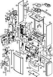
9. SPARESCasing AssemblyItem Description 50/65 70/901 Door Assembly 222331 2223212 Control Facia Assembly 222334 2223243 Control Box Assembly 221599 2215994 Side Casing Assembly L/H 209888 2098885 Top Panel Assembly 208730 2081006 Back Panel 208734 2081297 Side Casing R/H Assembly 209889 20988937
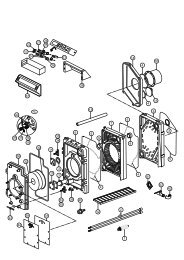
Control Box AssemblyItem Description <strong>Trianco</strong> Part NoControl Box Assembly 2215991 Relay 545722 Relay Base 5017653 Tank Limit Stat 2080964 DHW Stat 2215725 Tank Stat 5000396 Boiler Limit Stat 2068927 Boiler Control Stat 2068968 Programmer 207110 not shown38
7910SEE PAGE 32 FOR BAFFLECONFIGURATIONS56Boiler PartsItem Description 50/65 70/901 Boiler & Tank W.U. 208750 2097502 Flue Spigot 207772 2077723 Expansion Vessel Bracket 207274 2072744 Flue Cover 208780 2088035 Flue Mount 222219 2222196 Flue Mount Insulation 222197 2221977 Burner Assembly 221300 2213308 Oil Line (not shown) 207019 2070199 Burner Mounting Gasket 221173 20879910 Burner Mounting Flange 221333 -39
AIR VENTTANK LIMITTHERMOSTAT -YELLOW(TOP OF TANK)BOILERCONTROLTHERMOSTAT -GREENBOILER LIMITTHERMOSTAT -WHITEHOT WATERTHERMOSTAT -ORANGE(MIDDLE OF TANK)TANK THERMOSTATBOTTOM - BLUE(BOTTOM OF TANK)•YELLOWCONTROL BOXASSEMBLY•••208771••WATER TANKGREEN3-WAYVALVE22mmBALLVALVEBOILER BODYWHITEFLOW SWITCH22mmBALLVALVE•CENTRAL HTG FLOWFLUE DISCHARGE KITCOLD WATER FEEDDHW WATER FLOWCENTRAL HTGPRESSURE RELIEF40
By appointment to H.M. Queen ElizabethThe Queen MotherManufacturers of Domestic BoilersTRIANCO LIMITEDThorncliffe, Chapeltown, Sheffield S35 2PHTel: Sheffield (0114) 257 2300Fax: (0114) 257 1419www.trianco.co.uk© <strong>Trianco</strong> Limited, Copyright in this brochure and the drawings or illustrations contained in it is vested in <strong>Trianco</strong> Limited and neitherthe brochure or any part thereof may be reproduced without prior written consent.<strong>Trianco</strong> Limited’s policy is one of continuous research and development. This may necessitate alterations to this specification.Printed by WFO Press Ltd. (01709) 740078 July 2004 Item No. 221724 Issue No. 4